Maritime Content
Showing topics in Historic Vessels to 1914, Maritime WWI to 1939, Maritime WWII, Maritime Cold War to 1990, Maritime Modern, Work in Progress - Maritime, Ready for Inspection - Maritime, General Maritime modelling chat, Kits, Aftermarket & Themed Figures and Reference Material posted in for the last 365 days.
- Past hour
-

RNLI Severn Class Lifeboat : Airfix : 1/72
Faraway replied to Faraway's topic in Work in Progress - Maritime
I’ll post photos tomorrow, but so far the hull is appalling. Nothing fits. Bit it will…… Jon -
RNLI Severn Class Lifeboat : Airfix : 1/72
Faraway replied to Faraway's topic in Work in Progress - Maritime
Same problem, nightmare to fit the hull sides and bottom, transom fit is awful. They are not moulded to fit at all. I’ve sanded lots off and finished with filler. -

RNLI Severn Class Lifeboat : Airfix : 1/72
bobsyouruncle replied to Faraway's topic in Work in Progress - Maritime
Jon, would you mind looking at your bow thruster parts when you get to them and see if they’re moulded the right way around? Mine weren’t. Wondered if it was a one off or not. Easy fix if not. Enjoy. - Today
-
Sorry for the delay, I wanted to get far enough into the sweep winch to tell it's story. This is still part 1 of the winch, more detail will follow next week. However, before we dive down that rabbit hole, a few bits of finishing on the foc's'le The foc's'le has no fewer than 15 vents of 4 different types plus a chimney from the forward crew flat stove Here is a shot of the starboard side with all those vents fitted. There seem to be at least two types of mushroom vent used on flowers, round capped and square capped. This is in addition to the FMV's which I believe stand for "French" Mushroom vent with a grill on the side of the square cap. The vents on the main deck seem to all be labelled FMV, I made them a few months ago. However, the foc's'le vents would appear to be normal MV's.. The GA has these drawn as square capped so that's what I've made for the 6 and 8 inch vents, the 4 inch short vents on the deck edge look like round capped vents and they are very short. They are also painted black for some reason, they stand out on the pictures Anyway, that's more than anyone really needs to know about vents. Note also the freestanding voice pipe behind the windlass and the short stanchions round the 4 inch platform, part wire, part rod, will be fitted later when I've made up the access ladders, the platform is still removable. I also bit the bullet and filled the vertical T sections on the bridge wing framing down to 2.5mm from 3 mm wide. I think it looks much lighter as a result, but it's hard to appreciate from the photograph OK, now onto the winch. As I've said before, the Clarke Chapman winch the JL has drawn on the Taplet Publications, reproduced in the warship perspectives book just doesn't fit Alisma. The steam engine is in the way. Weirdly, he has reproduced it on the plan, but missing it's motive force (no engine). Also, the side elevation of that winch does not match the drawings I have of Alisma from the yard. I'm not sure why, it's a real puzzle. In his book on trawlers and drifter, he has an outline sketch of Robertsons Minesweeping winch which is powered by side mounted cylinders in the manner of the windlass. This one close fit, but (and there is always a but) its side elevation also doesn't match the shipyard drawings I have of Alisma. Also, Alisma's drawings call the winch out as made by Clarke Chapman The Roberson winch in the trawler book only has two shafts, a drive shaft and the main drum shaft, Alsima's GA clearly shows three shafts, see below, sorry its a bit small. Now, I honestly remain puzzled as to the purpose of the third shaft. Even more confusing, I found this picture of a clarke chapman twin drum cargo winch with side cylinders but only two shafts This picture shows a sweep winch of the side cylinder type with two capstans per side, a large forward capstan and a smaller rearward one giving purpose to a third shaft. Apart from the plan view on Alisma only showing one capstan per side the rest of the detail on this picture matches This picture of a Roberson winch seems to be the model LJ drew in his book on trawlers, just for completeness Now, a sweep winch is really just a special version of a twin drum cargo winch and much searching unearthed this drawing of a cargo winch which in elevation scales identically to the GA drawing with a modification on the side frames, but the wheels/shafts are spot on. The lower drive shaft has the ability to engage with the main drum drive gear, or the upper shaft gear via that handle on the left just to the right of the lower steam cylinder but engaging it would not appear to do anything as that upper shaft has no purpose I remain very confused and really I stopped making progress because I couldn't understand what that shaft was for and being an ex-engineer, that has really bothered me and taken up far to much of the time I have left on this earth So, leaving this puzzle aside, I decided to make the thing anyway, doing what I knew. I did draw it all in both 2 and 3d and printed a version with the upper shaft carrying small capstans, but really I don't believe that is right now. Picture below just showing the parts loosely fitted up and it's missing a lot of other stuff. One thing that did solve however, was this cryptic note on the rigging plan - "Portable Wood Grating" . When I offered up the printed model to the ship, it was clear that the brake wheels could not be reached by the operator and the grating has to be at the level of the top of the central ammo hatch. Luckily, I had installed the rear deckhouse doors with a very high threshold and so I had space to make up platforms either side with grating top and a step that still fit under the opened doors. This is the first thing on the whole winch story that I like, they will be toned down of course, actually probably painted and the wood showing through due to wear. BTW, that raised hatch to the rear of the winch position also clash with the port steam cylinder, more adjustment needed. Now, clearly I can't have such a large lump of plastic on the model, the sweep winch must be metal, so I've commenced making the parts I'm confident of The base-plate The brake drums, see also the pattern for the side frames ready to cast Mould first pour complete. The long pour tubes help press air out And a shot of my highly non-professional (frankly dangerous) arrangement for low temperature allow casting, talc is used as a release agent. The clamps allow the mould to be tapped to remove the air while the metal is still molten Taking shape, three cast and cleaned up. The original would have cast side frames, so I'm happy with this approach and with the drums made up and added, trying an angle for the level wind mechanism which will be scratch made in brass. The framing on the ends of the brake drums was filed in brass, would have been neater as an etched part, but I'm not waiting, they are a trifle rustic And lastly, the first of the two steam cylinders being test fit So, if I can't find a solution to the mysterious third shaft, I shall just build what matches the drawings and try not to worry about its lack of purpose, though I admit this may require therapy... Cheers Steve
- 377 replies
-
- 1
-

-
- Flower Class
- 1:48th scale
- (and 1 more)
-

RNLI Severn Class Lifeboat : Airfix : 1/72
psdavidson replied to Faraway's topic in Work in Progress - Maritime
Ooh, nice I built one in a GB a few years back I found @davecovs build on ATF very useful https://www.tapatalk.com/groups/airfixtributeforum/airfix-1-72-rnli-lifeboat-group-build-davecov-s-bu-t5663.html -
The plating does split opinion, I have their Yamato kit as well, its a little less pronounced on that, it really isn't that pronounced on this really but the light above it accentuates it, either way I prefer it to a smooth hull, One thing I'm contemplating though is giving the hull a once over with a sanding pad, they have created very impressively crisp riveting detail......but im pretty sure she would be mainly welded construction as she was built early thirties, seems a shame to remove it, though it's so fine you'd not notice it with a matt finish unless you're looking for it,
-
Thanks everyone, yes as others have said there is a new website address www.starlingmodels.co.uk Unfortunately sales of the 1/350 kits have not been what I had hoped, there is a lot of kits available in this scale now and I'm not sure that direction is the best use of my limited time and resources. There will be some small 1/350 kits still, those that don't require resin cast hulls and too many small parts. The HMS Nadder kit may be the one that is made available again but I will have to cost that one out before making a decision. Most likely the other kits will gradually be discontinued as they go out of stock or I will perhaps look for some other means of makng them available once that happens. The 1/350 accessories range will still be available and will be added to when opportunity allows. For those who prefer the more affordable and less space demanding smaller scale, there is a lot in store to interest you. Mike
-

WW1 Destroyers - looking for a model kit
Mike McCabe replied to Big Dave S's topic in Maritime WWI to 1939
Thanks Paul, it is unfortunately not available at present, I am hoping to redesign and update it at some point Mike -

Admirable Class Minesweeper Black Cat 1/350
Harrysgrandad replied to Harrysgrandad's topic in Work in Progress - Maritime
NOTE For those of you outside the UK who may not have heard of him, Paul Hollywood is a minor celebrity (very) judge from a programme called ‘Bake-off - and it’s usual celebrity spin off) one of the many inane reality/baking/cooking/dating/endurance programmes that have inundated the the television channels of this ‘sceptered isle’😝. As they invariable do, these people immediately push out a vast quantity of merchandise in an effort to max out their 15 minutes of fame, and my daughter bought into it!!!!! Rant over.🤬 -
Admirable Class Minesweeper Black Cat 1/350
Harrysgrandad replied to Harrysgrandad's topic in Work in Progress - Maritime
Meanwhile, in a parallel universe! By some unexplainable mystery of intergalactic serendipity this Black Cat kit (HCMS Sackville) arrived on my doorstep at the same time as the ‘Admirable’ kit. So in an attempt to convince you all that I am a little bit organised I decided to prep this kit, sort out the sea base and prime it alongside this build, wartime mass production?????? WIP for this will arrive afree another time warp! -

1/700 Whangaroa scratchbuild
ArnoldAmbrose replied to PieterC's topic in Work in Progress - Maritime
G'day @PieterC, thanks for the quick reply. I agree, styrene outer sheathing would probably make attaching extras easier than to balsa. I've done three scratch-built hulls to date, all in 1/600 scale, the most recent being the German WW2 light cruiser DKM Karlsruhe. The next I'm planning is the WW1 battlecruiser HMAS Australia. She's the same length as Karlsruhe but has about 80% more beam so I was going to use 1mm thick styrene. Karlsruhe was done with 0.75mm styrene and the earlier Fletcher-class destroyer was done out of 0.5mm. I think I'll still use my method without balsa for Australia as I have a hull diagram with a reasonable number of bulkheads. But in future I want to do some small ships too and if I can't get hull diagrams with sufficient bulkheads I think your balsa in-filling will be the way to go, followed by thin styrene cladding. I'll look around and see what glues are available in my part of the world. Many thanks again. Now get on with your model, I want to see what comes next. 😁 Regards, Jeff. -
Great work! Moving turntables sounds great for future posing options, hopefully painting them doesn't lock them up. I had a lot of fun with the amount of movable/posable stuff on my Chikuma build. I'm afraid I'm in the camp that dislikes the hull plating detail. Even if accurate to plans it's visually overdone, but I'll be watching to see how well your paintwork tones it down. In any case enjoying this build the kit looks fantastic as does your work on it.
- 24 replies
-
- 1
-
-
- Japanese Navy
- Very Fire
- (and 1 more)
-
Hey Jeff, thanks or your comments. The balsa is glued between the frames/bulkheads as by wedging you might move the bulkhead. The balsa is shaped by sanding it back to the bulkheads and decks while checking the form from prints of the relevant sections. Theoretically you could leave it there and fill the balsa and paint it. Plating with styrene gives you a better painting surface though and makes it easier to glue on other parts . I am using zap-a-gap medium superglue for both filling and plating. Maarten Schönfeld who taught me this technique tends to use normal plastic glues. As Maarten is originally an aircraft modeller I think the technique comes from building free flying aircraft models. The technique gets better with practice. Start with a simple hull without sheer and accept that the first one wll probably be a failure. My most complex hull, mv Straat Clarence, took four hulls to get it right. Styrene and balsa are cheap though.
-
.thumb.jpg.8e014d2f7c29f4fc3c8f480a617bc78b.jpg) Finally some progress on "Popov". Added the propellers, rudder, davits, anchors & chain as well as the variuos poles and masts. Now to the boats, followed by rigging and flags. I like the look of her.
Finally some progress on "Popov". Added the propellers, rudder, davits, anchors & chain as well as the variuos poles and masts. Now to the boats, followed by rigging and flags. I like the look of her. -
Hi All, Update, more resin/3d printed parts going on, I know it's apples and oranges, but compared to yamato she is tiny granted one is a heavy cruiser and one is a super battleship but the picture doesn't really justify just how small the cruiser looks by comparison, and she was not a small ship at over 600ft long, Look photo etch! @Jerry L it took me about two hours each side to put all these little plastic bits on, this is only about a third of it, word to the wise the instructions ask you to drill two holes for each part, but the nubs on the back of the parts is so small that the holes are always going to be too big and spaced too far apart, in the end I drilled one small hole just as a locator for the part and removed the two nubs and stuck them on that way, Really chuffed with this first bit of etch going on, I've managed to do it so that the turntables still move beneath, there's a lot more to go on so if that will stay the case I don't know, Everything black is resin/3d printed, the dimensional coordination is really quite something, the small range finders at the front of the tower sit onto a small plastic protrusion, and the resin part that supports the rangefinder slides on top of that protrusion, and includes the gussets, fit was absolutely spot on and lined up perfectly with a small recess on the front face, And further proof there is now a little more etch on her, lot more to go yet though, Thanks for stopping in, Sam
- 24 replies
-
- 5
-
-
- Japanese Navy
- Very Fire
- (and 1 more)
-
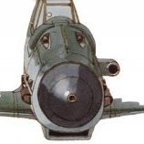
Thanks Rob, I'll confess I am rather pleased with how the sea fury came out, she's painted in humbrol 15, I did one coat by brush, sanded out the imperfections and bits of dust etc, then did a second coat by brush again and then did the same getting rid of bits etc, then sprayed the third coat, mixed it about 3 parts paint to 1 part thinner, then quickly put it on the cupboard to dry for 24hrs, I'm doing the G-fury one in red as well, I'll share that when I'm done with her, Edit, in not on the cupboard lol
- 24 replies
-
- 1
-

-
- Japanese Navy
- Very Fire
- (and 1 more)
-
RNLI Severn Class Lifeboat : Airfix : 1/72
ArnoldAmbrose replied to Faraway's topic in Work in Progress - Maritime
G'day Jon @Faraway, the photos are visible here. Re photo hosting, yesterday arvo Flickr wouldn't show all of my photos but decided to behave itself later in the evening. The photos were visible on the forums though. HTH. Regards, Jeff. -
Kriegsfischkutter—1/72–Special Navy
Faraway replied to Jeff.M's topic in Work in Progress - Maritime
It often surprises me what kit producers miss. All looking very good. Jon- 56 replies
-
- 1
-
-
- WWII
- Kriegsmarine
- (and 1 more)
-
Admirable Class Minesweeper Black Cat 1/350
Harrysgrandad replied to Harrysgrandad's topic in Work in Progress - Maritime
Rob The HD foam was nearly as tough to roll out as my pastry😝 -
.thumb.jpg.b4a5069fd2c2dd5708ce1694345c5b11.jpg)
Admirable Class Minesweeper Black Cat 1/350
robgizlu replied to Harrysgrandad's topic in Work in Progress - Maritime
I'd guessed that but had difficulty reconciling this with the ?"frame" that the ship rested on in the first pic - it must be the heat Rob -
I'm definitely in a colour mode at the moment. First it was HMS Burdock in her Blue and Yellow, then the midget sub in grey, white, black and brown and now this, which is by far and away the most colourful so far. And it'll make a nice change to use gloss paint, that will make applying decals SO much easier. So, here are the obligatory prebuild photos. (which I hope you can see, as I can't see them on the photo host site) Very colourful decals I've even bought the recommended Humbrol colours, never sprayed Humbrol enamel paint before, so that might be a challenge. Jon
-
1/700 Whangaroa scratchbuild
ArnoldAmbrose replied to PieterC's topic in Work in Progress - Maritime
G'day Pieter, it's an interesting method of hull construction you've used. Is the balsa simply wedged in between the frames/bulkheads or do you glue it in? And if so, what do you use to glue balsa to polystyrene? Thanks. Your method here looks a lot quicker than the plank-on-bulkhead method I've used on my scratch-built hulls. And it looks very nicely done, too. Regards, Jeff. - Yesterday
-
 Another lovely build, looks superb to me 👍 Love the colours and the still waters👏👏👏
 -
On we go. Plating the hull begins with the bulwarks as a starting point in .3mm think styrene. Note the stem has a loose 'fold', I will come back it that later. The rest of the hull is filled using evergreen strip and sanded back to match the earlier wood shape. And the bulwarks are made larger as pictures of the real ship show larger and deeper bulwarks than the original drawings. And this is the fold mentioned earlier. It is cut and sanded back to the balsa ad carefully built up again in 1 mm wide strip in order to get he outward curve that makes 50s and 60s ships so nice to look at. The coming few days will be about filling, sanding and filling again and after that the hull is set aside and I'm starting the superstructure.
-
Admirable Class Minesweeper Black Cat 1/350
Harrysgrandad replied to Harrysgrandad's topic in Work in Progress - Maritime
Hi Rob When I first retired I went through a ‘home baking life crisis’ and my daughter bought me a Paul Hollywood branded rolling pin which turned out to be a total no-no. it now lurks in my workshop and I use it to manipulate the HD foam into a vague replica of a sea swell, the way I used to roll my pastry out, lumpy and uneven🤬


-
Forum Statistics
255.1k
Total Topics4.4m
Total Posts -
Member Statistics
36,955
Total Members6,336
Most Online
-
Who's Online 169 Members, 3 Anonymous, 5,928 Guests (See full list)
- Grey Beema
- Dave Swindell
- Gekko_1
- Muddyf
- SnøMotion
- Riksbar
- Bonhoff
- YorkshireT
- coolhand
- Colin W
- Wandering Minstrel
- Lummox
- CH-53D
- Parkersen
- Foxtrot21
- Aidan.H
- Rodders154
- MrB17
- Circloy
- hakkikt
- Stu_davros
- invidia
- Enzo the Magnificent
- Lightningboy2000
- TEXANTOMCAT
- Claes
- Dan Bilek
- MartynCLT
- Lazlo Woodbine
- fatfingers
- chrisrope
- echen
- MOK61
- JWM
- petetasker
- Technics
- AliGauld
- Alinus777
- Ham
- yezda
- pengland007
- kifobefa
- Russmeister 101
- John
- Ngantek
- 2996 Victor
- elger
- ReverendNL
- Ralph21075
- Bonkin
- One 48
- mikesmodels
- Mike N
- Redstaff
- Creepy Pete
- MikeA
- Skawinski
- bootneck
- Nerkaman
- Hunker
- cpoud117
- Wolfhound32
- Pauly Boy
- mdesaxe
- averarandy
- lazyeagle
- junco
- Bengalensis
- JeroenS
- flarpen
- Rabbit Leader
- PhantomBigStu
- kiseca
- scautomoton
- GTZIM
- tempestfan
- fubar57
- vfma115
- Gatesy64
- Teeradej
- cmatthewbacon
- k7rkx
- hendie
- jhutchi
- Stephen
- Stef N.
- sniperUK
- NickD
- Linden Hill
- Head in the clouds.
- JCH
- Mr T
- Murat Yagan
- Kenny Horne
- A6Intruder
- Bo hermansen
- Wez
- AlexDX
- Ossington 2
- robonth
- Alpha Delta 210
- Runscott
- GRK
- Mike McCabe
- Bedders
- Illusive
- peabo
- neil5208
- Terry1954
- The Spadgent
- martinBK
- Mals Way
- smd425
- pigsty
- vs322
- Pete_W
- Pete in Lincs
- Hamster Volant
- Pin
- The_Lancaster
- philipp77
- Back in the Saddle
- bar side
- Faraway
- spitfire
- patjb
- Totally Mad Olivier
- Troy Smith
- bigbadbadge
- binbrook87
- ocatlub
- UC880
- Jabba
- tornadoxz630
- Muzz
- baldwin8
- ModelingEdmontonian
- Morantbay
- Sgifford
- Mr. Model Maker
- rossm
- flieger
- booze_epicure
- djktrumpet
- MaRi
- Billy54
- Tbolt
- Artur
- John_W
- Plasticbasher
- HK-500
- Simon in Wales
- Count Spatula
- aidy
- Cotswold Eagle
- nheather
- MikeC
- GaryShwod
- Hencore
- JoshWilson
- Roel_D
- Giorgio N
- Matt Crane
- Fred piket
- Johnson
- SashaGrace
- Saeran
- Hamden
- Adam Poultney