


hendie
-
Posts
7,835 -
Joined
-
Last visited
-
Days Won
7


_5.56mm_Rifle_MOD_45162138.thumb.jpg.053e4f85b299efc3857bfa5c1911dc3c.jpg)
Recent Profile Visitors
11,359 profile views


hendie's Achievements
")
Completely Obsessed Member (6/9)
25.1k
Reputation
-

1966 Batmobile with 3D printed Bat Signal
hendie replied to hendie's topic in Ready for Inspection - SF & RealSpace
I was going to print a few sets off on and stick them on eBay, but if anyone here is interested, just PM me and I'll see what I can do -
Worst Gigs (in no particular order) Billy Idol at Edinburgh, Ingliston Queen at Glasgow Apollo (just after release of Bohemian Rhapsody). The Who at Glasgow Parkhead. More for the venue than the band though the Sensational Alex Harvey Band really blew them off stage. I've never been to a stadium gig since. I saw the Who at Glasgow Apollo 2 years earlier and they were great. Echo & the Bunnymen at Edinburgh Playhouse Best Gigs (in no particular order) Siouxsie & the Banshees at Edinburgh, Clouds - on tour with Johnny Thunders Heartbreakers and before they had a recording contract The Saints at Edinburgh, Clouds Psychedelic Furs in Aberdeen, Ruffles (the week before they got their recording contract) Nick Cave at Edinburgh, Princes Street Gardens ACDC at some University hall in Glasgow back in '76 Sparks at Edinburgh Odeon The Banshees pretty much every gig on the JuJu tour, but most notably the Liverpool gig, though that may be cos of the end of tour party afterwards The Banshees in Hong Kong '82 (I still have most of the tour posters from the JuJu tour, plus the tour poster from Hong Kong, sadly the tickets have long disappeared) Sophisticated Boom Boom at Edinburgh, Niteclub Spike Milligan at Edinburgh, Usher Hall Anne Pigalle at Edinburgh, somewhere Velvet Underground at Edinburgh Playhouse Other notable gigs Linton Kwesi Johnson Altered Images (before they had a contract) David Bowie Comsat Angels the Adverts Ultravox (with John Foxx) the Wake the Cramps Killing Joke
-
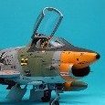
Ah, just saw 'em after zooming in. If you want to add a further splash of color to that gearbox area, the swash plate was normally a grey color. Check out the HC2 in the walkrounds area - there's some good shots of the gearbox and rotor head at the end of the thread.
-
that is looking very impressive Chris.The extinguisher is a nice touch. Don't forget the wiper motors on the floor.
-
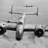
Canberras or Proportional Photorecce in progress
hendie replied to perdu's topic in Work in Progress - Aircraft
Oh, first in, aside from Bill that is. I'll have a Traquair Ale ana mince pie please -
Wasn't there a helicopter around here once? Asking for a friend, you understand. 😄 (P.S. nice design/print work Tony)
-
Or maybe a gallery for customers (not the designers) to show off their work?
-
Thanks very much for the comments Mark. I really appreciate them. You're right though... packing those parts takes up a decent amount of time. I've seen some taking up to an hour, but much better than having to print, package, and send a replacement package.
-
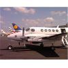
Obviously something for the Navy?
-
Lynx is looking top notch there Bill And the printed parts look excellent - can't wait to see you begin work on that.
-
ooooh very nice, Chris The sheepskin looks fine - those covers always looked really tatty and dirty
-
Chris if they were anything like the UK versions, the emergency pack - the big curvy part of the seat base - that was yellow, with a sheepskin bum comforter laid on top. That might be completely useless information for you, I'm not sure.
-
Mirage IIIO 1/32, Scratchbuild
hendie replied to Bandsaw Steve's topic in Work in Progress - Aircraft
Nice update and nice progress, Steve. "Ovals"? You've got a better memory than me. She does look nice with some clothes on now, even if it's only her underwear- 485 replies
-
- 2
-

-

-
- RAAF
- Scratchbuild
- (and 1 more)
-
FYI there's only a few days left on Elegoo's Easter sale. I just picked up a Saturn with 25% off.
-
Inverted Gull Wing, the American way. It's a Corsair!
hendie replied to giemme's topic in Work in Progress - Aircraft
Masterful work once again Giorgio.

