View New Content
Showing topics posted in for the last 14 days.
- Past hour
-
That's like the pots I have with the colour number on the bottom. The one that is different is the Humbrol pot which has a label.
-
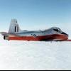
Hi I am building a very early F6, circa 1956/57 vintage. The build is nearly finished and I am soon to sort out the antennas. I have looked at countless F6 photos and I conclude that early F6 carried only short "whip" antennas, four of them. A pair on the spine, one between the Sabrinas, and one under the port wing, near the tip. Reading up tells me that the Rebecca aerials were flush mounted on ventral panels for this mark. The pair of "rod" antennas in the ventral area appears around 1960, so too late for me. Is anyone able to confirm/challenge or otherwise add to this please. Apart from Rebecca, was the only comms fit the UHF and the aforementioned whip antennas? Thank you, kitchentable
-

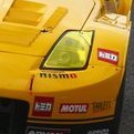
Barn Find R34 GT-R - The “Secret Side Project”
RossFMJ replied to SnøMotion's topic in Ready For Inspection - Vehicles
That's very nice that is . The moss is spot on, I have some of that myself out-doors. -
 Hi Gary, two years down the track. It seems the dreaded “pictures not showing” problem has reared its ugly head again. I’ve now got one of these and not knowing a great deal about the various Victor changes over the years I’m trying to educate myself. I don’t know if you can do anything after all this time but it would be great if you could. Cheers, Mike. (Usually in sunny Darwin but currently freezing in Melbourne)
 -
Although Germany continued to produce a surprisingly high number of aircraft under extreme circumstances, as evidenced by the production figures often quoted in various books/on-line/documentaries etc. for 1944 and 1945 it is hard not to think that even their well oiled war machine and factories didn't have to make compromises in order to simply get flyable stuff out of the factory by using what was ever was available. Not an obsession with sticking to a given specification, be it a G-10/12/14 etc., which is what us modelers like to do and fixate on. I have absolutely no evidence to support this so I know many will disagree but for me it is simply a case of common sense and 'needs must' which at the time would have naturally obviated the need for strict adherence to a detailed spec that may have been laid down by the manufacturer given the chaos that must have existed at the time. As I say I'm no expert on late production 109's, which probably shows, but just simply applying some element of logic to the undoubted difficulties that must have existed at the multiple dispersed factories which were being subjected to varying degrees of disruption during this period. Kind Regards Pat.
-
Thanks Troy. I'm delighted that you enjoyed them! I'm pleased to say that my wife forgave me and accompanied me to the island!🤣
-
Hi @Nocoolname My only experience is with audio/dmx and multipin cables, but I guess you can relate it to lighting kit as well. Firstly it is important that the soldering station or iron hit the correct temperature, if it's too cold the solder won't melt. Another important thing is to have the right soldering tip for the job. If you are working with small soldering contacts or very thin cables in a restricted space then it may be helpful to have a tip that is suited for that kind of job. Otherwise you will not be able to be precise. Set of 'helping hands' might come useful if you don't have one. And of course a lot will depend on the size (gauge) and quality of the cables that you're working on, but it is also important to have a decent quality solder. One of the reasons why the connection failed may be that the soldering contacts were dry. Try tinning the prepped cables and before you solder them to the battery put a little bit of solder on the battery contacts as well. Then hold the cable at the correct connection point, add a bit more solder and this should be enough for a very good hold. Same thing again. Try to split the soldering into three parts. 1. Prep and tin the cable 2. Add some solder on the battery connection point 3. Hold the prepped cable to the connection point and add a bit more solder (and heat) Be careful not to heat up too much as you run a risk of melting something (super annoying when soldering small midi connectors) This is just my experience with all sorts of audio cables, but I hope that it make some sense. PS. Practice with some old cables, as soldering is all about muscle memory. The more you do it the easier it gets.
-
Yes we bought 15 ex USN machines.
-
That was my thought.
-
Blasphemi 1955 Chevy Gasser - Roadkill
Technics replied to Technics's topic in Work In Progress - Vehicles
It’s been a minute! There’s some “splash” of residue, lamps, decals and quick release details added. I worked on the tires, I sanded them down with some coarse files and “painted” on Tamiya cement / lacquer thinner. It’s the first of a few processes I’ll try out but so far it improves the out of box kit look drastically imo. Original is on the left. ( front tire ) painting back a desirable black with Tamiya cement. -
You also are aware that you mustn't try to retrieve your burnt toast with a fork at the bottom of the toaster, are you ? ( Could be entertaining though , if you fancy a jolt and hitting the ground )
-
She’s coming together rather nicely, and you’ve brought back some memories for me. The first Mossie I ever built was the Matchbox kit! Thank you for that Adrian.
-
 A quick update while the glued nose hardens. I forgot how simple this kit is. I love a plane that can be built in two small instruction pages. I found the kit with the fuselage ready to go together. I had to re think that because they have the tail strut getting sandwiched between the fuselage halves. You know this would be broken by days end. So I fixed it by breaking it. I drilled the shaft to accept hard steel wire. BTW. Don't ever buy the drills in the photo. They are the worst twist drills ever. They could hardly cut plastic. I wound up using a small Tamiya set right behind them. There's enough wire over lap that it'll be ridiculously strong. This is better. Now it's Ron proof and I wont have to worry about breaking it. Here you can see I started gluing sections of the fuselage together. As I was waiting for sections to harden I looked at the wings. There bunches of flashed over holes for stores on the lower wing. I only needed two on each wing for drop tanks. I marked the ones I needed and filled the rest with CA and baking soda. I bet you're wondering why I bothered backfill the holes? look at these pictures you can see surface distortion from the flashed over holes. On my Ylw 13 build I flat sanded distortion from the flashed over holes on the upper wings when it was in bare plastic. The distortion was still visible through primer so I filled and fixed it again. Or so I thought I did. It reappeared in the camo paint so I had to fix it again. and one more time after that. It was very hard to get rid of the hint of a depression. I think the thin flashing pushes below the wing surface when the sanding stick goes over it leaving the hint of depression. That hint showed in camouflage colors. I can't afford to mess around with silver lacquer wings that will reflect every surface disruption and irregularity. I'm hoping the backfilling will prevent the flashing from perpetually flexing away from the sanding stick so it can be planed flat and level in one effort. That's the hope. The nose glue should be hard enough to go back to now. I should have a good a update later. be well Ron
 -
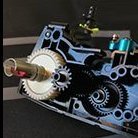
Half way there! This is the kit of the Metro 6R4 rallycar of 1986. The original engine was a Rover V8, but as there wasn't room for the big V8 so the rear two cylinders were cut off! Four wheel drive was fitted for maximum grip and as allowed with any World Rally Car to be as fast as possible. Also it was my first go at making seatbelts with the photo-etch and fabric, very stressful, I think I'll stick to decals.
-
- 1
-

-
 GROM-AT gets the prize for me😂👍
 -
Wylam and Nye’s drawings are exceptional in their details and I’m sure many are framed on thousands of walls around the world. However they are often referred to as “Art” and many sources seem to concur with that analogy. I’ve had their books and admired their drawings, but I wouldn’t trust them as being accurate. If you google them, you’ll find many have the same take on them. They do look spectacular though when framed and most people wouldn’t know the difference. Cheers Jeff
-
Tamiya 1/72 Mosquito VI 464 Sqdn HX912 ‘SB-F’
Roland Pulfrew replied to Rafwaffe's topic in DH Mosquito STGB
Definitely looking the part now. She’s looking very handsome with her markings. Looks like we’ll have another finisher soon!! -
 Thanks Skiffy! Yep, the Space Marine Rhino is a tricked up FV 432. I took my sons out to a place near Stirling to have a hoon around in one. Fantastic day out! Drive me closer, I wish to strike him with my sword! And GW's:
 -

1/144 Academy (Minicraft) KC-135R USAF
Blue Monday replied to Lex77's topic in Small Is Beautiful GB
Good luck with your build. This is another type I’d love to have in 1/144 scale and this kit is probably the most buildable. BM. -
 That’s fantastic! Beautiful piece of work.
 -
by the Sunday rags
-
Welcome Lewis, from up the road in Aberdeen. I went to a few of the Leuchars air shows and miss them too. One memory that sticks in my mind was the Russian Flanker display on a very foggy day. Can’t remember what year that was though?
-
Fantastic. The very first photo, I had assumed at first glance was a photo of the real thing and I was waiting to read "here's what I was aiming for". That's a very nice backdrop in addition to the great build.
-
 A fine museum. I went there in 2007 or thereabouts, and again a few years later. I wonder how much of it is still in existence . The Antonio overhaul facility on the airfield. At the time of my second visit there were many Indian An-32s and an Ukraine Border Force An-26 in the circuit, as well as lots of tired An-24/6s scattered around. On my way first visit a FAN An-26 was flying circuits. Also on the first visit I took a trip over to Kharkov for a visit around the An-74 factory. I was working on both occasions.
 -
.thumb.jpg.2c282efcc138b7cf7f1e1586a9c534d2.jpg) I’m sure you know about it, but there are great photos in the walk around section on this forum, great for all those little details.
I’m sure you know about it, but there are great photos in the walk around section on this forum, great for all those little details.


-
Forum Statistics
254.8k
Total Topics4.4m
Total Posts -
Member Statistics
36,915
Total Members5,082
Most Online
-
Who's Online 144 Members, 1 Anonymous, 1,207 Guests (See full list)
- John Thompson
- JWM
- marques
- Simon Cornes
- Roger Holden
- exdraken
- Duggy
- Dudko210
- Carllu
- John Tapsell
- Ben Hartmann
- Thom216
- HiPoDad
- Blue Monday
- Franz75
- Giorgio N
- mgleslie
- mike_hore
- Autle
- samhobbs
- SleeperService
- LHR-days
- Stephen
- Shuttle
- szeregowy
- Glen
- Steve Coombs
- ScanmanDan
- Dave Fleming
- stuartp
- TallBlondJohn
- seacon
- Andy H
- NAVY870
- Dr. Quack
- Robert Stuart
- MrB17
- jsolo
- Amethyst
- Aeroplane Man
- davpar59
- PaK_Wagen
- Dave Spencer
- Fightingcocks
- VolkerR.
- kitchentable
- RossFMJ
- Doc72
- R T Fishall
- AdrianMF
- GioCare
- PatG
- Wolfhound32
- Blacklion
- Microbacchus
- NDB16
- Skawinski
- Mynimal
- Iain Ogilvie
- Chimpion
- vildebeest
- JonH
- Casey
- Alpha Delta 210
- t15dja
- Nocoolname
- Zorglub
- rudi
- Whitewolf
- Trublewalkin
- cmatthewbacon
- MarcNewitt
- bentwaters81tfw
- Mascota
- Tegethoff
- Ryri
- Rabbit Leader
- Mark Proulx
- jimmaas
- XV571
- Old Submariner
- GMK
- Ryan Hothersall
- Creepy Pete
- Whofan
- Paul E
- Mig Eater
- Troy Smith
- dnl42
- stever219
- dambuster
- Jacky W
- bombernut
- Johnson
- Fnick
- Smudge
- HPoirot
- Stu_davros
- Tbolt
- dasmithers
- misterblank
- Teuchter
- Jb65rams
- delide
- LimaOperator
- cherisy
- Kiwidave4
- aircraftkit
- AlbertLima
- Riksbar
- Dan Bilek
- Doccur
- Mycapt65
- Knevi
- PinUp
- KRK4m
- rafalbert
- Marcus.Q1000859
- Angus Tura
- Caulkhead
- Elias
- RAF4EVER
- Runscott
- hendie
- airbus
- Roland Pulfrew
- DeepSea
- HK-500
- Massimo Novi
- ModelingEdmontonian
- 457
- Spooky56
- Davetur
- Andrew D Jolly Rogers guy
- Jo NZ
- lyn
- batcode
- Pullin Gs
- scautomoton
- Pete_W
- Technics
- mhaselden
- fjdsouza94c
- othertales