dambuster
-
Posts
1,042 -
Joined
-
Last visited


dambuster's Achievements
")
Very Obsessed Member (5/9)
403
Reputation
-
@tempestfan What do you mean by the Phase III outers? I’m guessing you mean the Nacelle with the Viper installation, but this was not specifically a Phase III mod, but was also fitted to aircraft configured as Phase II. Peter
-
A few more airframes with this marking: XH979 XH912 XJ125 XH885 although partly obscured by a different coloured panel. There is a photo in the Ian Allan book on the Javelin which shows a formation of 85 Sqn aircraft, it does look like they may all have this marking when examined closely: XH696 XH695 XA816 XA836 XA774 XA804 XA820 XA830 There doesn’t seem to be any obvious commonality between any of these airframes. Sorry if this doesn’t help explain why it is there; nothing in Roger Lindsay’s two Javelin monographs or Cold War Shield that gives a reason. Peter
-
 Never ever ever call it a ‘plane’, that’s what you use in woodwork. 😀
 -
It also appears that the rear of the fuselage is a little bit pinched, something doesn’t look quite right around the wing trailing edge to fuselage fairing. If the wing leading edge is too deep, which appears to be the case, then this will look odd when placed alongside the Airfix FB5. Peter
-
Don’t forget that the rear blades are slightly shorter than the front ones. Not sure from your photos if the ones supplied are all the same length. Peter
-
Latest news is that the FAA have called for inspections of door plugs on 737-900ER aircraft as there have been issues noted apparently with these same bolts by airlines that took the initiative to inspect following the Alaska incident.
-
There is a drawing and side profile and some photos in the SAM Modellers Datafile on the Mosquito. The winch was an ML Type G mounted at the forward end of the bomb bay. This winch was used on many other Types, for example the Meteor TT20, where it was mounted on apylon above the inner starboard wing. Peter
-
This seems to be a case of poor design thinking. If the requirement is to plug the gap where a door is not required by an airline, then why use something that can be opened? Would it have been possible to produce a different mechanism to replace the lower hinge, using the same fuselage fittings, that still enabled the plug to be dropped into position but then secured more robustly? At the very least someone should question what was the need for the lift assist hinges on a non-functional door? My understanding is that they are required on the emergency exit to prevent the door falling back once activated, which you obviously would not want in an emergency evacuation situation. Making the plug removal ‘easy’ in that it only required four bolts to be removed and providing ‘lift assist’ would encourage use of this as an access to the fuselage during any maintenance where the interior fittings were removed. Peter
-
Andrew Brookes in his book on the V-Force states that the Coningsby Wing were to be the Skybolt Squadrons - 9, 12 and 35 Sqn. There is no specific reference to the source for this. Peter
-
The functioning emergency doors in these locations have the same mechanism but are activated by an operating handle. These are emergency doors only so do not work like the normal entry/exit doors. When the door handle is moved it lifts the door 4cm to clear the stop pads and rollers. It then needs a push to open, and hinges at the bottom to lie against the lower fuselage, a bit like a cargo door in reverse. One point that has been mentioned in the Alaska accident is that the aircraft was flying through some turbulence just prior to the plug opening. This supports a theory that with no locking bolts to prevent upward movement of the door, and without the maximum internal/external pressurisation differential, the door moved upwards in the turbulence the 4cm needed to disengage from the stop-pads. Peter
-
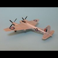
The only problem is that the Dora Wings 1/48 Mk I scales out about 14” too short being the right length for the shorter Mk II at 29’ 6”. Maybe not quite so noticeable in 1/72. Peter
-
@OneEighthBit The figures you give are pretty much those in the Air Britain Miles Aircraft books. I may have caused some confusion as I was pointing out that for a Mk I the kit is too short, as it scales out at around 29’6” which is the length of the Mk II. Regarding wingspan for the Mk Ii, some wer built with the original 39’ wingspan, later retrofitted with the shorter 35’ 9” span which was the standard for the Mk II. The tailplane for the Mk1 was 11’ 0” in span, but this was increased in production aircraft to 12’ 5 1/2” to compensate for the increased weight of the RT equipment as it was introduced to replace the voice tube between the cockpits. There is no specific mention of any change to the Mk II tailplane so it is my assumption that it also had the longer tailplane. I haven’t measured the kit to see how it compares. Peter
-
Great work, and a conversion I have also considered. From studying photos of the Mk II the wing fillet panel was enlarged to basically include the fairing into the wider cowling, up to the point you have added the semi -circular fillet. I also noted that the kit scales out about 1ft short in length and 9” short in span for the Mk I. i assume you know that there was a longer tailplane fitted to the later marks , I haven’t measured the kit one to see which version it represents. Peter
-
A few points from the NTSB briefings. They believe that there is no link between any previous pressurisation warnings and this incident. It appears that there may have been a problem with one of the three pressurisation systems which caused a warning light, but flights were permitted to operate with only the other two systems serviceable. As has been reported, the door plug has been found. The four bolts that prevent the door from translating upwards to clear the stop pads were missing. It is the stop pads that take the pressurisation load from the door plug and distribute it to the rest of the airframe. The upper locating guides in the door plug were fractured. So it appears that the door plug was able to move upwards (as it is designed to do for maintenance) and the pressurisation load passed from the stop pads to the locating guides, which failed. From the presentations the door only needs to move upwards by 1.5 inches to clear the stop pads, and also the lower hinges have lift assist springs to prevent the door falling back into place. It is not known whether the bolts were installed and came out, failed, or were not present. Photos in the presentations show the bolts fitted with nuts with safety locking to keep them captive. Peter
-
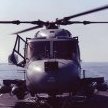
Airfix Sea King HAS 5 1/48 Dipping Sonar? 826 Sqn 1983
dambuster posted a topic in Aircraft Cold War
Apologies if this has been answered elsewhere but I’m trying to understand why the Airfix HAS5 has the internal sonar rig fitted but the instructions tell you to fit a blanking plate over the bottom of the fuselage. I think it was mentioned that the HAS5 airframe chosen by Airfix for the markings was being operated in the HU5 role, prior to conversion. Should a ‘normal’ HAS5 have the sonar well left open? I’m looking to model an HAS5 from 826 Sqn based on RFA Fort Austin, March-May 1983 down in the Falklands. ‘B’Flt crews had just taken over the det, and I assume that as the airframes were already in situ that no specific Sqn or Flight markings were applied. Can anyone confirm this please? I have records of codes in the range 140-147, some relevant serials, but no record of any tail letters, which I assume weren’t applied. Thanks Peter