

Mike
-
Posts
1,019,661 -
Joined
-
Last visited
-
Days Won
42


_5.56mm_Rifle_MOD_45162138.thumb.jpg.053e4f85b299efc3857bfa5c1911dc3c.jpg)


Recent Profile Visitors
141,595 profile views


.thumb.png.03cf829e3ab23b3f04fe2590dd61bc3c.png)
Mike's Achievements
")
Constant Member (9/9)
36.6k
Reputation
-
I have been struggling with migraines and helping my ageing parents all week, and haven't had time to look at the forums until now, and here you are determined to make something out of nothing, i.e. an honest mistake. If that's all you have to worry about, you're a lucky man.
-
Do.217K-1 WWII German Bomber (48273) 1:48 ICM The origin of the Do.217 was the Do.17 ‘Flying Pencil’ as it was colloquially known, with a brief to extract more power from the engines, extend its range and give it a better bomb load amongst other improvements. The resulting airframe was sound, and left other early war designs in its wake, becoming known as a heavy bomber in Luftwaffe service, something they were very short of throughout the war. It was also a versatile aircraft along the same lines as the Ju.88, and was adapted to many other roles like its predecessors, including the night fighter role, to which it was eventually well-suited, although not initially. Various engine types were used through the endless rounds of improvements, with radial and inline engines fitted in a seemingly random pattern throughout the aircraft's life. The 217E was the first of the production airframes, using BMW engines for level and dive-bombing roles, skipping to the K that adopted the stepless, all-glazed forward fuselage that had been deemed a standard requirement for the He.111 and later He.177, the design for the K very similar in shape to that of the 177. The K-1 was the bomber standard, adding extended wings and the capability to carry the Fritz-X glide bomb to the -2, and the -3 capable of carrying both the Fritz-X or Hs.293. A switch of engines to inline DB.603s saw the mark changed to M, while the sub-variants stayed the same, but with an extra 100+ horsepower under each wing improving performance, and probably reducing drag slightly thanks to the sleeker cowlings. The night fighters ran concurrently with the bombers, had a crew of three in an enlarged cockpit and solid nose sporting four MG17 machine guns and another four 20mm cannons in the front of the gondola for concentrated forward fire initially. The J-1 was disliked and the J-2 was little better, the upgrades still not enough to quell the complaints from the crews, leading Dornier to produce the improved N series, which eventually entered service in small numbers as the N-1 and N-2 variants before the type was phased out of service by mid-1944. The Kit This is a tooling revision from ICM, based upon the sprues from previous boxings by ICM, of which there have been many. This is the first time an injection-moulded kit of the K has been released, the previous options either a long out-of-production conversion kit for the aging Revell kit, or a similarly dated vacformed kit from another manufacturer. As a modeller that enjoys German bombers, and has a long-standing liking or all-glazed cockpits, this hits a sweet-spot for me on a personal note, and anyone that is interested in the type will appreciate both the ease of creating this unusual variant, and the wide availability that it should now enjoy. The kit arrives in a standard ICM top-opening box with the usual captive flap on the lower tray, the lid decked with a dramatic dusk (or dawn) painting of a K-1 flying high over broken cloud. Inside the box are twelve sprues of grey styrene, two sprues of clear parts, a large decal sheet, and a thick instruction booklet that is printed in colour on glossy white paper, with full colour profiles for the four decal options and the rearmost pages. Detail is up to the standard of the other kits from ICM and the Dornier Do.17/215/217 range of kits with which we’ve been blessed over recent years. The new sprues include a pair of fuselage halves, the clear parts, and new engine nacelles to replicate the specifics of the K-1, leaving plenty of other parts on the sprues, which are marked on the map with a red overprinting, and includes a set of larger bombs not appropriate for this variant. Construction begins with the well-detailed cockpit and fuselage, adding sidewall details to the two halves, and fitting additional details such as seats with supports, one on each side. The cockpit floor has a raised section for the pilot, to which the two-part bomb sight, a bulkhead insert, and the pilot’s five-part figure-hugging seat, plus two-part control column with yoke are installed. The completed assembly is inserted in the starboard fuselage half, adding a further stepped bulkhead behind it, and a stepped spar that slides through slots on the side, linked to a smaller bulkhead behind the bomb bay by the bay roof part, which has ribbing detail moulded-in, although it won’t be seen. The port side console has an instrument panel with dial decals applied, plus another four-part swivel chair that is placed behind the main cockpit for the rear-facing gondola gunner. As the fuselage parts are brought together, a bracket is trapped in the tail wheel bay, dealing with the seams in your preferred manner before moving on. A new clear domed nose is supplied, widening the hole for the nose machine gun if you intend to fit the double, or zwilling MG81Z there. Your choice is slid through the appropriately-sized hole and is joined above by a two-part instrument cluster attached to the top frame, gluing it to the front of the fuselage at the same time as your choice of tail fairing is fitted, either with or without twin rear-facing machine guns. The rear of the nose gondola has a single machine gun slipped through the hole in the glazing, fitting it below and behind the cockpit to close the underside, building the tail-wheel assembly from a yoke with surround, and two-part wheel with radial tread moulded-in, which fixes in the recess under the tail. The bomb bay is closed by use of a single part to depict the twin doors in the closed position, or you can add extra detail to the sides of the bay along with a triple-laminated C-shaped bulkhead to the rear, and a choice of bombs from the included weapons sprues. The bay doors are formed from a single outer door, plus a two-part inner door on each side, with a scrap diagram showing the correct layout when the area is completed. The upper wing is full-span, and is laid over the fuselage and short spar, closing it by adding the separate lower halves, followed by the elevator and H-tails that all have separate flying surfaces, as do the wings, with separate single-part ailerons, all of which can be posed deflected to give your model a more candid appearance. The radial BMW units are made up from two banks of pistons, the rear set having a bulkhead moulded in, then has the ancillaries and cooling fan added to the front. The cowlings are built in sections with exhaust stubs fitted to the insides, with three sections linked to complete the cylindrical cowling into which the engine slots before being locked in by the front cowling lip. This of course is done twice, as are the nacelles, which have ribbing detail moulded within and bulkheads to add detail and prevent see-through issues. The engine cowling slots onto the front of the nacelle and the retraction jacks are installed from above before they are fitted to the wing, as are the main oleos, mudguards and the two-piece wheels. You can also add in the gear bay doors at this point if you’re a masochist, or leave them off until main painting is over. The underside is completed by adding in the engine nacelles, and mounting the tail-bay doors to the sides, with a prism-like insert forward to complete the area. Flipping the model over shows the open cockpit, which needs the remaining parts adding before the glazing can be glued in place. A flying bulkhead or divider is adjusted according to a scrap diagram and inserted into the rear of the cockpit, adding a circular turret base behind it, then building the Pielgerat 6 (PielG6) sensor and base to a hole in the forward section of the canopy, a pair of aft-facing guns on the rear “cheeks” of the canopy, each one fitted with a separate gun. The canopy can then be glued in place behind the nose glazing, installing the domed turret glazing and another machine gun in the larger hole at the rear of the glazing, plus an antenna mast on the wing behind it, with two more under the wing and on the aft fuselage, low down on the side. The props are made up from a single part with all blades moulded in, then trapped between the front and rear parts of the spinner. The last parts are a set of cheek “pouches” at are fixed to either side of each nacelle with a set of curved grilles moulded in, and two exhaust deflectors on the top of the nacelles. Three-part auxiliary intakes are made and applied to the engine nacelles in front of the exhaust stacks, fitting three per engine, and making the prop from a three-bladed part that is trapped between the spinner and back-plate before being glued to the front of the engines. If you intend to leave the bomb bay open, the three last instruction steps show the three types of bomb that can be carried. SC500J, SD250Jb and SC250Ja can be fitted, all made from two halves plus a pair of perpendicular fins, braced by struts that link the fins, and in the case of the SC250Ja, a set of four “screamers” that cause the bombs to whistle on the way down to terrify their intended victims even more. The Jb and Ja bombs are options, using one or the other behind the larger 500kg units. Markings There are four decal options available from the decal sheet, with a variety of paint schemes, three using splinter on the upper surfaces that are shown on a greyscale diagram before the main profiles. The other option is an all-black machine with grey uppers with dark grey squiggle camouflage over the top. From the box you can build one of the following: Luftflotte 2, Mediterranean area, probably 1943 Stab/KG.2, Holland, 1943 1./KG.66, Chartres, France, Summer 1943 1./KG.2, Rhein-Main, 1943 Decals are by ICM’s usual partners, which is a guarantee of good registration, sharpness and colour density, with a thin gloss carrier film cut close to the printed areas. As is common now with ICM kits, there is a page of the instruction booklet devoted to the masking of the canopy, using the printed shapes on the right of the page and the diagrams on the left to create your own masks if you wish. It goes up to 54 thanks to the extensive glazing. Conclusion Another detailed kit of the Flying Pencil and its relatives, filling a dwindling gap in the range that’s now available from ICM. What’s next? Highly recommended. Available from all good model shops now. Review sample courtesy of
-
Fair enough - I'm just a simple fellow. Never even been to Eire or the top bit, to my shame
-
aboard. Can't fault your scale choice
-
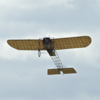
Horten Ho.229B (Superwings Series No.24) 1:32 Zoukei-Mura The Horten brothers were a pair of visionary siblings that designed a series of flying wing gliders in pre-WWII, during the period when Germany was prohibited by the terms of the Versailles Treaty from having an air force. Each design improved upon the last, and once the Luftwaffe broke cover in the Nazi regime’s expansionist phase before WWII, development began in earnest. The requirement in 1943 for a light bomber capable of the 3x1000 by the RLM, which was for an aircraft capable of carrying 1,000kg over 1,000km at 1,000kph set the wheels in motion that resulted in the Horten.IX, which is better known as the Ho.229, and is sometimes referred to as the Go.229 due to the fact that the Gothaer factory had been chosen for manufacturing of production examples. The flying wing had a low drag form, and the addition of two semi-embedded jet engines gave it the potential to fulfil the requirement, although it suffered a little from lateral instability due to its sleek shape. The first prototype flew un-powered and with fixed landing gear in 1944, with results that bore plenty of promise before crashing at the end of the flight due to a pilot error. Gotha altered the design in practical ways to ease production and increase longevity, as well as adding an ejector seat that was probably as much of a danger to the pilot as being shot down was. Another prototype was lost due to an engine fire, but this did not deter the RLM from striving to reach production, despite the worsening situation for Germany in Europe. A two-seat variant was considered for training and night fighter operations, but it never progressed further than a tubular framework rendering of the fuselage at the time the war ended, so details are limited and informed speculation plays a large part. The third prototype (V3) was an enlarged single-seater, and it was this that fell into the hands of the advancing US troops, and subsequently the Operation Paperclip team, who transported it to America with a host of other advanced designs that had been captured. It remains there to this day, in the restoration area of the Smithsonian's NASM, and you can see some stunning photos and interesting text on their mini-site. Hopefully one day we’ll see it restored, or at least see a replica that is true to the original design. The Kit It’s incredible to think that the original Ho.229A kit from Zoukei Mura (ZM) was released in 2014, and I’m still grateful that a pal of mine stood in to the queue at Scale Model World that year so I didn’t miss out while I was stuck queuing to get in. It’s eleven years since then, and much has happened in the modelling world and beyond, and yet here we are again with another 1:32 kit of the enigmatic and graceful Horten flying wing. This boxing includes all the parts of the original 2014 release, so from the box you can build either a single- or two-seater Ho.229 from the same box. That means that if you missed out on the original, you can remedy that without issue, other than wanting a second kit to build the unused option. The kit arrives in a similar-sized box that has the same footprint as the original, but is 2cm deeper to accommodate the additional sprues that have been added. The format is the same as the original, with a technical feel to the package that goes beyond a typical model kit and hints at model engineering, which is furthered by the skeletal internal structure that is typically present on ZM kits. The box art shows a two-seater night fighter in grey mottle fresh from a victory over a Lancaster bomber, the latter descending in flames as the Horten peels off to stalk its next target. Although this sort of incident would have been common in the skies of Germany toward the end of WWII, fortunately for the RAF and USAAF bomber crews, the 229 was too late to take part. Detail is exceptional as we expect from ZM, who specialise in making the modelling process a special event for anyone building their kits. The box is a top-opener, with a captive flap on the lower tray to further stiffen the box, and inside is a C-shaped divider that separates it into two identically-sized compartments that keep the sprues apart and prevents chaffing along with the individual clear film wrapping of the sprues. We mention this because many of the exterior skin parts are clear, that would be easily marred by poor packing and storage, so it is doubly important to keep everything crystal clear and undamaged, especially if you intend to depict your model with clear surfaces to show off the interior details. The instruction booklet is a weighty tome printed on heavy-stock matt paper with a red-brown theme reminiscent of primer red, and faux-official stamps giving the impression of authenticity to proceedings. There are ten clear sprues of varying sizes, which includes some stunning slide-moulded fairings for the nose and tail-nib, to single out just a few of the high points. There are also thirteen sprues in light grey styrene, most of which are half-box sized, and in a separate bag are two large decal sheets, one for each variant, and a sheet of pre-cut pale-green vinyl masks (not pictured). The final inclusion is a folded A3 sheet of glossy paper that has a full catalogue of their products printed in colour on both sides, covering both their 1:32 and 1:48 ranges. Construction begins with some choices, the largest of which is whether to build the original single-seat V3 variant, or the new two-seater B option, which is likely to be your first choice if you’ve got both variants, or have a thing for night fighters like I do. If you’re familiar with ZM instruction booklets, they can appear a little overwhelming on first look, but once you zoom in on each step, the complexity melts away and they’re very clear. They also give a lot of information to assist you with building and painting, there are names given to identify most major assemblies, and there are often photos of completed assemblies to help you get your model looking somewhere near to their example. The first few pages give background information on the type, then you must choose, with page numbers given to assist you with your chosen option throughout the build. If you’re prone to forgetting things like I often do, it may be sensible to put a line through any steps that aren’t required to help you focus. The build process begins unusually with the two Jumo 004 engines, which have a full suite of eight rows of compressor blades along the central shaft just like the real thing, trapping them, between the forward engine housing after adding the half-moon static blades within the shell first. Each pair is different, with much to be installed in strict order, and care will be imperative if you hope to install the turbine shaft, as the cut-outs in the static blades match the shape of the hubs. The intake bullet is a two-part assembly with the front compressor face added to the rear, which is then trapped between a pair of cowling parts split vertically, plus another pair split horizontally in front of those, forming the inner intake lip. The exhaust has two final phase rotors attached to a spacer, which is in turn glued to a set of stator blades, and finally the rear bullet is put in place. The engine shell is then completed by adding a ring to the back of the compressor phase, linking the exhaust assembly to the rear of the turbine shaft, and lastly enclosing the shaft and part of the exhaust assembly in more cowling that joins horizontally. The outer casing can then be painted up as per the photo instructions. A lot of ancillary equipment comes with a jet engine, and ZM have not skimped on parts here. There are a heap of parts utilised in completing the engine, and painting call-outs accompany them throughout. The final part of the first phase is to add the lower heat shields to the aft portion of the engine, which prevented the heat from damaging the combustible wooden skin. These are provided in crystal clear styrene, so that your work with the engines can be seen from the gear bays. As an option, you can cut some square sectioned parts from the sprue runners, and build them up into a trestle for one or both engines either to display them away from the aircraft, or to keep them safe while you finish off the build. An ingenious use of the otherwise wasted plastic of a sprue. Act two sees the building of the fuselage, which comprises a tubular framework that is very well depicted, starting with the longer two-seater variant. The lower frame is built up first after removing the foremost tubular-section, to act as the base on which the rest of the fuselage is built, and again you should paint this up as you go, due to the complexity of the finished article. The wing root formers are added to the extreme left & right of the fuselage frame, at which point it starts to look a bit like a Ho.229 for the first time. Various linkages and controls are added, reaching the forward fuselage to be integrated with the cockpit, which is built up later. The cannons and their ammunition feeds are added inboard of the wing joint, after which the engines are slotted into the lower fuselage assembly and held in place by the addition of the upper framework, so again – keep painting as you go along, or you'll regret it. Fitting this part properly is critical, and takes up two pages of the instructions, showing where it should locate several times from different angles. Another page is devoted to showing the finished article in picture form, which should give you the impression that if you err, you will struggle fitting the outer skin, so take care, test-fit and do it right the first time. The single-seater sees you skipping ahead to page 29 of the booklet, and whilst the majority of the process looks very similar to the new version, there are different parts, the section removed for the two-seater is left intact, and the guns aren’t fitted on this V3 prototype. The cockpit section helpfully shows a photo of both options one above the other, showing the differences clearly along with the pages that you will need to refer to when building you choice. The two-seater has the rudder bar split into separate L-shaped parts, adding the rudder pedals to the ends of the lower brackets, fitting each one to its respective side-console, which is further detailed by fixing instruments, levers and so forth, detail-painting it as you go. You have a choice of a styrene instrument panel or a clear part, using the same decal or decals either on the faces of the instruments, or on the backside of the clear part to give the impression of dials under glass. The two side walls with their consoles are brought together on either side of the new floor, trapping the panel in place, then installing the control column, and the two-part rear-seater’s console after detail-painting it and applying more dial decals. The completed assembly is shown being lowered into position in the fuselage from several views, carefully aligning the pins and receptacles that hold it in position. ZM took a view that the two-seat cockpit would be a more deliberate affair to separate the crew from the heat and noise of the engines and guns, hence the style of assembly, which is substantially different from the single-seat cockpit of the V3 that is a simple contraption suspended between the framework of the fuselage, followed by another page of photos of the built and painted cockpit in place. The fuselage is covered in translucent outer panels to the framework. You will need to decide what to do about them around this stage, and choose whether to model it with a "ghost" skin, partially paint it, or go the whole hog and paint it completely. Of course, you could also go the extra mile and depict your 229 unpainted using some wood effect decals where appropriate, or do it yourself with oil paints used to depict the grain. The nose cone for the V3 is a work of styrene art, having been slide-moulded as one piece that incorporates the nose, engine intakes, forward cockpit sills and the outer fuselage leading edge. The two-seat nose cone is necessarily longer, and has a pair of trunk extensions cemented behind the intakes, fixing a thick piece of clear glazing in front of the pilot to protect him from incoming rounds during combat. It has a two-part underside terminating in the pen-nib fairing at the rear, deciding whether to deploy the four spoilers by using their moulded-in actuators, or cutting them off to fit flush with the outer skin. Scrap diagrams help by showing correct alignment of both options, then the upper fuselage is applied over the top along with a pair of clear engine covers that can be glued down or left loose to show off the engines, and could be adapted with tiny magnets if you wanted to avoid losing them over time. For the single-seater, the lower fuselage skin is made up of three main parts, which fit onto attachment points moulded into the bottom of the fuselage framework, so care and careful gluing is the order of the day, especially if you are leaving any of the panels unpainted, fitting the airbrakes and their actuating rams in the same way as the 2-seat. The V3 upper fuselage comprises a single large upper piece and different crystal-clear engine cowlings that allow you to show off one or both of your engines in the same way as the 2-seater. As usual with the wings of a ZM kit, there is a simplified version of the internal structure in the shape of ribs and stringers that give the wing stiffness and allow the suspension of ancillary equipment within the framework, and they are the same for both options. The main internal structure is a single moulding, to which is added a more detailed inner end-profile. A set of four fuel tanks are added into the mid and leading edge of the inner two-thirds of each wing, and a single piece depicting the actuating mechanism for the outer flying surfaces. At this point you'd be forgiven for thinking that you should add the skin to the wing, but instead you attach the wing structure to the fuselage using a quartet of pegs for each one, each of which is moulded to a small square of outer-skin. A couple of small interior detail parts glue directly to the lower wing interior before it is added, and then you fit the top wing, encasing the innards forever. All the control surfaces are poseable, with elevons along the trailing edge, the inner sections of which also act as flaps. On the top and bottom surface of the wing tips are the drag rudders, a set of two-section spoilers than allow lateral direction change. Each one plugs into a slot in the top and underside of the wing skins, and can be posed closed by cutting off the actuators and gluing them flush with the outer skin. Several scrap diagrams are there to help you get them sitting correctly, as well as a couple of photos of the finished article in the deployed position. Finishing the model depends on which option you have chosen, differing substantially for the two-seat night fighter with its extended nose and radar. First are the common parts, starting with the nose gear bay doors that are fitted on either side of the bay, hanging vertically to the ground, followed by the main gear doors, both captive to the main strut, the upper door held away from the leg by a support jack, the correct angle shown in scrap diagrams. A pair of small inner doors separate the bays with one V-shaped part, and drag chute compartment doors behind the gear bay are fitted, adding an antenna to a hole in front of the main bays. Finishing the cockpit involves building a pair of ejection seats that both consist of the main seat-pan with a choice of moulded-in belts or bare, surrounded by a two-part frame and an optional head rest, noting the detail-painting instructions in a scrap diagram to the side. The pilot’s panel has a clear gunsight installed in a central slot, then the seats are fitted in the two compartments in preparation for adding the canopy, which is a large clear part with a separate framework underneath, posing it open or closed by reference to the scrap diagrams nearby. Wingtip lights are inserted in triangular cut-outs in the wings, adding a pitot probe to the port side, D/F loop on the spine, gun barrels outboard of the engine intakes, and a clear landing light on the nose gear leg. The last step is to add the delicate antennae for the Fug.220 Lichtenstein radar, which are provided as four complete parts that minimise alignment issues, although you are still given plenty of scrap diagrams to ensure everything is neat and tidy, one of which shows the painting and decaling of the integrated dipoles, some of which are covered in red/white stripes, with decals on their supports. The V3’s final assembly differs by making just one seat, with the same choice of moulded-in belts or not, and optional headrest. The canopy is smaller, and consists of a short curved clear part with the aft fairing and central frame glued to the rear, or a simple one-part clear option if you don’t like having to glue clear parts to styrene. Both options are mounted over the styrene frame, which has a guide added beneath, and the windscreen is glued in after adding the gunsight. The seat is installed, posing the canopy open or closed with the help of the nearby diagrams, then fitting wingtip lights, D/F loop, pitot probe and gun barrels as per the two-seat option. Markings There are two new decal options on the sheet for the new two-seater, and the original decals have been replicated for those that wish to build the original V3 airframe that adheres more closely to the reality of what was built during the last days of WWII. From the box you can build the following: Ho.229B Red 12 Ho.229B Red 8 Ho.229A-0, White 14, ISS I./JV44, German Mainland, Oct.1945 Ho.229A-0 JG.301 German Mainland, Sept.1945 The decals have been designed by Radu Brinzan for Zoukei Mura, and they are printed anonymously to the highest standard. Sharpness, colour density and registration are excellent, and the matt carrier film is cut close to the printed areas except where necessary to prevent them from folding up on themselves during application. Conclusion There was a time when dreaming about a 1:32 mainstream injection-moulded kit of the Ho.229 was considered unlikely to come true, but it did. Now the range has widened again with a two-seat variant that has been tooled to the same high standards as the original boxing from Zoukei-Mura. Coupled with the option of building the original V3 option from the same box, this represents an excellent option for the larger-scale modeller. Very highly recommended. Available soon from your favourite stockist of high quality model kits worldwide Review sample courtesy of
-
Seems like the guards weren't "live" in more ways than one Dumb, avoidable, and could have been SO much worse. We are already short of serviceable gear, so losing more in such an unnecessary manner would have been dreadful. Someone deserves a good drubbing and a career change to something more suitable to their mettle (door wedge perhaps?) after that. Anyway - You've all done a decent job of keeping away from politics, and those that touched on it haven't been taken up on it, so let's ensure we keep it that way going forward
-
After making sure the meatbags were safe, I'd hope to be able to grab either my NAS or backup NAS before everything went down, so if I had one of those, I wouldn't mind losing everything else, as it's insured. The most important bits that aren't tech would have to be the menagerie and her indoors My biggest problem would be remembering what I'd lost. My stash is catalogued, but everything else isn't
-
Three Swann Morton #3 ferric handles, with a #11, #10 and #15, all attached to a magnetic tool rack on the side of my spray booth. I never use anything else for proper cutting. I do have a couple of X-Acto and similar handles that have various tools in them, but they're not for cutting your average model part.
-
Quite right - that's not four words. Oh wait... wrong thread. AAAGGGHH!!!!! [Thread closed - go find the new one]
-
Fair play, that's excellent
-
Hi Tim, As Ed says, you've posted this thread in the wrong place, but I've moved it for you as you're new. Please take the time to wander around the forum to familiarise yourself with where everything can be found, as it'll pay dividends in future. It'll also keep you from having threads removed, as once people age out of their "newness", threads can sometimes be deleted rather than moved if us Mods are busy at the time. to the forum while I'm here
-
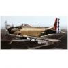
Supermarine Spitfire TR.9 (A05143) Two-Seat Trainer 1:48 Airfix The Supermarine Spitfire was the mainstay of British Fighter Command for the majority of WWII, in conjunction with the Hurricane during the Battle of Britain, with the Mk.IX being the most popular (with many) throughout the war, seeing extended periods of production with only minor alterations for the role for which it was intended differentiating between the sub-variants. Originally requested to counter the superiority of the then-new Fw.190, a two-stage supercharged Merlin designated type 61 provided performance in spades, and the fitting of twin wing-mounted cannons with accommodating blisters gave it enough punch to take down its diminutive Butcher-Bird prey. The suffix following the mark number relates to the wings fitted to the aircraft, as they could vary. The C wing was also known as the Universal Wing, and saw extensive use because it mounted two 20mm cannon in each wing, the outer barrel usually covered by a rubber plug. The main gear was adjusted in an effort to give it more stable landing characteristics, and bowed gear bays removed the need for blisters on the upper wing surface, helping aerodynamics. The Mk.IX is considered by many to be the definitive variant of the Merlin-engined Spitfire, and over 5,600 of this type were made during WWII, the majority built at Castle Bromwich. Although there were two known two-seat two-seat Spitfire conversions during the war, one of a Mk.V by a British squadron, and one Mk.IX by the Soviets for training their pilots, it wasn’t until after the war that it became official, starting with one Mk.VIII that was built by Vickers as a demonstrator. Ten T.Mk.IX trainers were exported to India for their training needs, with a further six sold to the Irish Air Force for their training and conversion requirements in 1951, converted from redundant Mk.IXs. The Irish airframes were also able to be used for gunnery training thanks to the retention of two .303 machine guns in the outer wing stations, one in each side, that allowed novice pilots to engage in target practice with the security of knowing that they had a tutor in the back seat in case of issues. Of those six, four survived retirement and went into service in the warbird community, taking paying passengers on pleasure rides that are still ongoing at time of writing, despite a recent forced belly landing by one of the small fleet that was light enough for the pilot and passenger to walk away almost unscathed. Hopefully that airframe will be back in the skies once repaired and its engine has been rebuilt after the shock-load imparted by the prop when it impacted the ground. The Kit This is the first boxing of a new tooling from Airfix, one of the first to have the exterior fully riveted, which is bound to split opinion, as usual. Speaking personally, I like them, as they add extra visual interest in areas that might otherwise look bland, and although we all know that rivets aren’t generally holes in the skin, we also know that windscreens aren’t 6” thick, and that modelling is always a compromise in some shape or form. Now that’s out of the way, let’s get on with looking at the model. The kit arrives in a top-opening red-themed box, with a painting of an Irish TR.9 in green with their orange/green yin-yang meatball roundel on the wings and fuselage. Inside the box are four large sprues and a smaller one in dark grey styrene, a separately bagged clear sprue, decal sheet, and the instruction booklet that is printed in spot colour on white paper, with full colour profiles of the decal options on the rearmost pages. Detail is excellent, extending to the usual points of interest that include the cockpit, gear bays, plus other exterior features both raised and engraved. The inclusion of a fully riveted and panel lined exterior skin is a new feature for Airfix, and adds to the appeal for many modellers, as above, which coupled with Airfix’s clever engineering of their kits and excellent marketing and distribution network, makes for a better product for us modeller. Construction begins with the dual cockpit, and while the component parts will be very familiar to anyone that has built a Spitfire before, the unusual aspect is the provision of another seat and controls in the rear. Because the front cockpit has been moved forward to accommodate the extra seat, the bulkhead with the pilot’s instrument panel has a shallower profile than the norm, attaching the compass mount in the footwell hole, and adding this and the forward spar to the port sidewall insert. The forward floor has a pair of pegs removed from underneath, fitting rudder pedals, then sliding it into the cockpit from the front via the footwell cut-out, and securing the rear through the spar before adding a cross-bar to the seat frame and putting it into the slot that marks the rear of the first cockpit. A short bulkhead is set behind the front cockpit, making up another floor section with rudders, and sliding that carefully into place, taking care not to bend the narrow areas that project into the front cockpit and through the rear bulkhead. A narrow port side console is made from two parts plus a decal, fixing it to the cockpit side straddling both compartment, locating it on the recesses moulded into the wall. The front seat will be very familiar, consisting of the pan plus two sides, and an adjustment lever on the starboard side, attaching the support frame to the rear, then fixing it in the cockpit after the glue has cured. The starboard cockpit wall has three pegs removed from the rear, and a wiring loom fitted before it is joined to the growing assembly, adding another slim console with throttle quadrant and decal to the starboard side after the two walls are in position. The tutor’s control column is a two-part assembly, fitting a ledge to the starboard footwell before it is closed in with a shaped bulkhead, then sills are fixed to the top of the cockpit assembly, and another two-part control column for the trainee is added. The tutor’s seat is made in the same manner as the front seat, attaching it to another seat frame with rail glued across the top, sliding the completed assembly into the rear of the cockpit assembly, then fitting the front and rear instrument panels after painting and decaling them with dials and other details. The trainee’s sidewalls receive a throttle quadrant and landing gear control assembly, the former on the port side, the latter on the starboard. A support is fixed between the top of the tutor’s panel and the roll-over behind the trainee’s head, then you have the choice of whether to populate the cockpit with pilots or not. Two crew members are included on the smallest sprue, and the pilot in control has separate arms to allow for a more realistic pose than the old hands-on-lap chaps of yesteryear. Both pilots are inserted into the cockpit at this stage, adding the arms to the pilot once they are in position, but if you don’t feel the need, you can leave one or both in the box. Before the fuselage can be closed around the cockpit, you should make the decision whether to pose the canopies open or closed, as the sills need to be removed for the closed option. Fortunately, Airfix have included two jigs for the sides that allow you to cut the forward sills off without issue, providing you don’t forget yourself and glue the jigs in place in a moment of madness. To pose the canopies open, the access doors are cut out along the thinned edges, as shown on the instructions, with replacement parts provided on the sprue, noting that the aft door is much shallower than the pilot’s, and as it is post-WWII, you can paint the diagonal crowbar bright red without risking pillory from the purists. Another piece of equipment is added to the moulded-in ribbing in the top of the fuselage on the starboard side, a filler cap is inserted in front of the windscreen, and a platform is installed in the belly aft of the wings, ready to receive the two relocated oxygen bottles that usually stand upright behind the pilot seat. The completed cockpit can then be trapped between the two fuselage halves, which is where we can see a new engineering decision that will lead to a better joint on the cowling over the Merlin engine. Instead of moulding half the cowling into each fuselage half, it has been created as a separate part that is given the correct shape and form by using sliding moulds, which results in fine seamlines that need little clean-up, and shouldn’t reappear like many Spitfire cowling seams have in the past, which I’m sure many of us can attest. Each elevator panel is made from upper and lower skins, slotting into the tail on either side, adding a full-span flying surface across the concave trailing edge, and trapping it in position with an insert in the centre. This allows the modeller to deflect it as they wish, adding the rudder behind, which can also be deflected for a more candid look to the finished model. The lower wings are full-span out to the tip-joints, and have a pair of radiator housings inserted after fixing the cores front and rear inside them, and gluing the cooling flap to the rear, which can be set open or closed. Flipping the lower wing over, a pair of circular bay walls are added to the cut-outs, linking them with a pair of parts that perform the dual task of bay sides and also act as spars to keep the dihedral of the wings from sagging. A circular light is embedded in the lower wing toward the trailing edge, then it can be mated to the fuselage, gluing the upper wings over the top, and installing the ailerons in their cut-outs near the tips. You have the option for wheels-up or down with this kit, the easiest option being in-flight, requiring the installation of the fixed tail-wheel under the rudder, and a custom set of main bay doors that have spacers moulded-in, which prevent the parts from dropping into the bays, and give enough space for the simplified wheels to attach to the integrated axles. To model the TR.9 on the ground, a pair of struts are made with separate scissor-links and captive bay doors, both inserting into the bays and locating securely in position with the help of some sensible engineering. The wheels are moulded as tyres that have block tread (typical of post-war use) moulded-in along with the rear hub, adding the front hub before installing them on the stub axles at the lower end of the leg. While the model is inverted, an L-shaped pitot probe it glued under the port wing, and a pair of small hooks are installed between the radiator housings. Attention moves back to the fuselage, concentrating on the nose and cockpit to finish off. The six-stack fishtail exhausts are moulded on the same sprue as a set of tubular stacks, so ensure you fit the correct option before proceeding. Each set comprises two parts that hold three stacks each for extra detail, hiding the mating surfaces inside the cowling after they have been inserted into the slots in the sides of the nose. The four-bladed prop is moulded as a single part that is bracketed by the spinner and back-plate, which is placed against another plate that is skewered by a stepped pin that should allow the blades to spin if you are careful with the glue. The assembly is then glued into a cup that slides into an oversized hole in the front of the nose, again being careful with the glue to keep the blades moving. As mentioned earlier, the canopies can be posed open or closed, and by now the decision should have been made. To have the canopies open, the windscreen, aft section of the forward cockpit and the windscreen/spoiler for the aft cockpit are glued in place, fitting the two openers in the retracted position as shown on the diagrams, fixing the open doors in the down position on the port side of the fuselage that should have been cut out earlier. If closing the cockpit, a small section of the front cockpit sill should have been removed using the jigs supplied, allowing the combined opener and fixed aft section to be glued in place over the cut-out. The same aft opener is used for both options in this kit. Markings There are two decal options in this kit, one in service with the Irish Air Corps, the other in civil service as a warbird. From the box you can build one of the following: Spitfire TR.9, B Flight, Irish Air Corps/An tAerchór, Baldonnel Aerodrome, Dublin, Republic of Ireland/Poblacht na hÉireann, 1951 Spitfire TR.9, Iver, Buckinghamshire, England, 1969 Decals are by Cartograf, which is a guarantee of good registration, sharpness and colour density, with a thin gloss carrier film cut close to the printed areas. For the Irish option, the widths of the orange/white/green stripes under the wings are shown for those that prefer to paint larger markings to avoid carrier-film steps, and separate Trestle-Here markings are thoughtfully included on the decal sheet. Conclusion While the TR.9 Spitfire played no part in the Battle of Britain or the rest of the war, it was an interesting bit-part player post war, and is a familiar sight in the skies around Britain and at airshows. It’s also about the only way any of us will ever get to fly in a Spitfire without using a time machine. Airfix have done a great job of tooling this kit using modern techniques, and the upgrade of detail levels really shows. Very highly recommended. Review sample courtesy of
-

1/48 - Supermarine Spitfire Tr.9 by Airfix - released
Mike replied to Homebee's topic in The Rumourmonger
Halvsies? -
1/48 - Supermarine Spitfire Tr.9 by Airfix - released
Mike replied to Homebee's topic in The Rumourmonger
Let's rejoice at that, rather than get bogged down re-stating (for the Nth time) whether we do or don't like rivets. I for one am really looking forward to the kit, as it'll help me depict an aircraft that I really can't afford to book a 30 minute flight in. I must go and have a look at the decal options... We'll post up our review just as soon as the kit arrives -
Eduard Lysander Mk.I/Mk.III Löök (644305 for Airfix) 1:48
Mike replied to Mike's topic in Aftermarket (updates/conversions)
I think we might have been separated at birth


