Search the Community
Showing results for tags 'Eduard'.
-
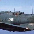
I'm quite excited to start this! Here's a box shot - I'll be building Eduard's 1/48 P-51D, in markings of an aircraft flown by Lt James Hickey, out of Martlesham Heath. My late father was RAF groundcrew, and based at Martlesham until it became an American base in 1943, when he was transferred to work on Wellington bombers at Chipping Warden. So, a family connection, albeit a slightly tenuous one!
-

Eduard P-51B/C Engine (6481004 for Eduard) 1:48
Mike posted a topic in Aftermarket (updates/conversions)
P-51B/C Engine (6481004 for Eduard) 1:48 Eduard Brassin Eduard released their new P-51D Mustang to much joy, followed later by the razor-backed P-51B/C both in 1:48, making theirs the new de facto standard in the scale. We’ve already seen a handful of upgrade sets already, and reviewed a group of them here a little while back. Now the engine set has arrived. As usual with Eduard's larger resin sets, they arrive in a Brassin-themed black-orange-and-yellow cardboard box, with the resin parts safely cocooned in bags between layers of grey foam, and the instructions folded around acting as additional padding. This set will furnish you with almost everything you need to depict the Rolls-Royce Merlin, or Packard-built Merlin in astonishing detail, after removing a short section of the nose from your kit, safe in the knowledge that as it was designed by the same folks that engineered your kit, so it’ll fit well, as I’ve found in the past. As to what else you’ll need, that extends to the usual paint and glue, especially super glue (CA), and some lengths of fine wire of various diameters including 0.2mm, 0.3mm, 0.4mm, 0.5mm, and 0.6mm, all of which have their diameter and length shown on the instructions, along with a representation of the shape it should be formed to in colour to further assist you. Inside the box are fifty-five resin parts in two shades of grey, a small Photo-Etch (PE) brass fret, and the instruction booklet that is printed in colour on both sides of five sheets of A4 paper. Detail is exquisite, and the build process is covered step-by-step over thirty instruction stages, with the adaptation of the fuselage halves only undertaken at step 29. Construction begins with the engine block, which has the space in between the cylinder banks detailed by adding an insert into the V, fitting the generator to the side, and detailing the supercharger with seven additional parts. The part that filled the void between the cylinder banks is wired with twelve lengths of 0.2mm wire courtesy of a highly detailed step with seven exploded views to assist with their locations. The reduction gear housing is fitted to the front of the block, adding the horseshoe-shaped header tank and some pumping gear over the top, fixing some wires to the port side of the block, between the block and the supercharger on both sides, then adding several mechanical linkages from the PE sheet on both sides. The magneto and boost control equipment are mounted over the supercharger, and more wires link it to the engine, followed by fitment of the six exhaust stubs on each side, with a choice of shrouded or unshrouded pipes, painting the shrouds the exterior camouflage colour. Engine bearers are built from two sides with a horseshoe cross-member, plus PE actuators on the starboard tip. Additionally, a hose is applied to the starboard bearer for P-51B-5 and P-51C-1s, then the Merlin can be lowered onto the four bearers, fitting a long actuator down the port side from the PE sheet. The next few steps install several hoses around the engine, then detailing the firewall bulkhead with a strapped down tank, a PE skin to the lower portion, several wires of 0.4mm diameter, and a resin hose, after which it can be mated to the rear of the engine bearers, running another wire down the top of the starboard engine bearer, and more hoses linking everything in the rear together. A spider-like assembly of 0.6mm wires is measured, cut and put together over the top of the motor, with scrap diagrams showing where they terminate, adding another into the rear along with two PE actuators, and a small resin block. The framework that holds the upper cowling is mounted over the engine, attaching to the tops of the engine bearers, whilst under the motor, you have a choice of two styles of supercharger intake trunk, one for the two types mentioned above, with a choice of a flush insert in the nose cowling, or one with auxiliary intakes on the sides, which gave rise to the perforated or louvred panels under the nose of the Mustang. A small PE part is added at the rear, and if you fitted the aux. intakes, there is a PE actuator and a small insert at the front of the unit. Your choice of intake is fitted to the motor, linking at the rear to the bottom of the supercharger. With the engine upright again, an actuator fits between the engine bearer and supercharger intake on the port side, and a PE strip is added to the starboard side of the intake for some options. A single resin part forms the structure of the nose in front of the engine, with two more formers fitted under the motor toward the rear, completing the assembly. Now you must remove the nose from the kit’s fuselage halves, as per the drawings marked in red, after which the engine assembly should slot straight in, adding the propeller axle to the front, and optionally you can mount the prop, depending on what state of undress the engine is intended to be. There are now all the cowling panels that are removed to expose the engine, eight in total, all but one require nothing more than to remove them from their casting blocks and paint them. The panel under the nose has two holes toward the front, into which the three optional inserts fit. You can have a flat panel for those airframes without the aux. intakes, louvred panels, or perforated panels with four rows of eight holes in the centre of the parts. These are glued into position and should sit flush with the rest of the panel, except for the louvres that project outward slightly. Markings There are no decals, but there are full painting instructions on every step of the booklet, using Gunze Sangyo Mr Colour H and C codes to assist with painting. There are also suggestions to help with the colours of the cowlings, which will of course be painted on both sides and strewn around the model. Conclusion Another awesome engine set with a significant wow factor. Take care to follow the instructions carefully, try not to rush, and remove paint from any mating surfaces, as tolerances are close for it to make a difference. Once complete, it should make viewers’ eyes pop when they see the level of detail. Very highly recommended. Review sample courtesy of -
I had big plans to enter quite a few GB’s this year, but installing a new kitchen over the last couple of months has seriously hampered my model making. The kitchen is finally finished (ish) now so I can start getting some decent bench time in again. My entry will be the Eduard Hellcat Mk.I. I will be making the box art version from 800 Sqn FAA, HMS Emperor, June 1944. This is a dual combo profipack so I have 2 of everything. All looks very nice. Few variations on the build as you can make a Mk.I or Mk.II. I like the look of the coloured PE especially, should look great in the cockpit. I'm hoping to make a start this weekend, fingers crossed. George
- 20 replies
-
- 11
-

-
Bf.109G-6 Erla Weekend Edition (84201) 1:48 Eduard With almost 34,000 examples constructed over a 10-year period, the Messerschmitt Bf.109 is one of the most widely produced aircraft in history, and saw active service in every theatre in which German armed forces were engaged. Designed in the mid-1930s, the Bf.109 shared a similar configuration to the Spitfire, utilising monocoque construction and a powerful Daimler Benz V12 engine, albeit an inverted V with fuel injection rather than a Rolls-Royce carburettor as used to power the Spitfire. Initially designed as a lightweight interceptor, like many German types during WWII, the Bf.109 evolved beyond its original brief into a bomber escort, fighter bomber, night fighter, ground-attack and reconnaissance platform. The Bf.109G series, colloquially known as the Gustav, was first produced in 1942. The airframe and wing were extensively modified to accommodate a more powerful engine, greater internal fuel capacity and additional armour. In contrast to early 109s, which were powered by engines delivering less than 700hp, some of the later Gustavs could output almost 2000hp with water injection and high-performance superchargers. The Gustav series accounted for a dizzying array of sub-variants, some of which featured a larger tail of wooden construction. Odd number suffixed aircraft had pressurised cockpits for high altitude operation, others were fitted with Erla Haube clear view canopy with clear rear head armour, underwing points for tanks, cannon or rockets and larger main wheels resulting in square fairings on the inner upper wings to accommodate them. The Kit This is a weekend reboxing of the G-6 variant of Eduard’s excellent Bf.109 Gustav range, eschewing the fancy pre-painted Photo-Etch (PE) and offering fewer decal options for the core plastic and a more pocket-friendly price-tag. The Erla name is usually associated with the improved visibility of the late-style canopy with reduced framework, but it also relates to the Erla factory at Flossenbürg that built many examples. Inside the box are four sprues of blue-grey styrene, one of clear parts, a pair of decal sheets, and a glossy instruction booklet, which is a step up from the older Weekend Editions, as are four decal options, up from the previous two. Construction begins with the cockpit, starting with the sloped L-shaped combined floor and aft bulkhead, adding twin trim wheels, seat-back, control column, then the clear fuel line, which is painted for the most part, leaving a short length clear to give the pilot a visual clue as to whether he’s about to get a sudden silence from his engine. The seat pan, rudder pedals and gun breech cover are also installed, adding four decal seatbelts, then completing the assembly with a forward bulkhead forming the foot well. The cockpit sidewalls are moulded into the interior of the fuselage halves, and has some additional equipment with decals fitted during the interior painting process, inserting the instrument panel with dial decal, and an optional 3x3mm piece of styrene from your stores glued to the bottom of the panel to accept a decal for the Rüstsatz 6 equipped decal options, holding instruments related to the cannon panniers. The fuselage is closed around the cockpit and spinner backplate, adding the exhausts into the nose before closure, and removing two small raised areas on the port cockpit sides for three decal options, and filling some access hatch panel lines on the starboard fuselage for three different options. The tail has the correct fin and rudder applied, with the elevators fitting on twin pegs to the sides. All the flying surfaces are separate with tabs fitting into recesses to allow deflection as you wish. The tail wheel is a single part that is trapped between a two-part yoke that is inserted under the fin in a recess. The forward fuselage is closed by adding a cowling insert over the top of the engine after installing the cannon trough parts underneath, applying Beule blisters into recesses over the gun bays, and a two-part intake trumpet for the supercharger. Two gun barrel tips are slid into the cowling troughs, and a hinge-line part is run along the split line of the two upper cowling panels, adding a rear stowage area behind the pilot to complete the area. The lower wing is full span out to the tip joint, and has four-part bay walls inserted around each of the two cut-outs, and a selection of holes depending on which decal option you have chosen, using the thinned inners as a guide to their locations. The upper wings have the tips moulded-in, and are laid over the lowers and glued down, inserting the fuselage in the gap between the roots. For some decal options the D/F loop base is removed at this stage, making good before moving on to fit the ailerons and leading-edge slats, the latter able to be posed closed by removing the short ridges from the inside so that they sit flush with the rest of the leading edge. Under the wing are the radiator fairings with front and rear radiator inserts included, plus a chin-mounted oil-cooler with a base, two radiator inserts and the exterior fairing. Behind the wing-mounted radiators are the twin-layer inner flap and cooling gills, and the outer flap parts, with their location and angle shown on a scrap diagram shown nearby. The landing gear legs are attached to the three-part wheels and captive bay cover, then inserted into the substantial sockets in the gear bays, needing only the brake hoses from a length of your own wire to complete them. Standing the model on its wheels, a clear gunsight is partly painted and glued into the instrument panel at the front of the cockpit, fixing the manual crank handle to the starboard side of the engine cowling if you wish to use it. The canopy opener has a curved piece of head-armour installed first, with a scrap diagram showing its orientation from the side, then a choice from two windscreen types is made, gluing one into the front of the cockpit, and the fixed rear glazing with two styles of aerial mast inserted into the hole at the back. The canopy can be fitted open or closed, adding a short length of wire to the sideways opening canopy to hold it in the open position. The decal option with a D/F loop has the loop inserted into the base, and there is an alternative pitot probe included on the sprues in case you’re a clumsy modeller (like me) and have knocked off the moulded-in part during the build. The prop is a single three-bladed part that is trapped between the spinner and back plate, then inserted into the hole in the nose to complete main construction, save for an antenna under the belly that is carried by two markings options, and requires a 0.5mm hole to be drilled before fitting. There are two styles of drop-tanks included, one of which has a tapered underside for improved ground-clearance, mounting on a four-pronged flattened pylon, and a pair of cannon pods are also in the box, made from two halves plus the barrel, and these are carried by two of the markings options. Markings Four markings options are included, so you have a choice of interesting schemes for your Gustav, as follows: Bf.109G-6, Hptm. Heinrich Ehrler, CO of 6./JG5, Alakurtti, Finland, July 1943 Bf.109G-6/R6, W.Nr.15367, Oblt. Herwig Zuzic, CO of 8./JG1, Leeuwarden, The Netherlands, July 1943 Bf.109G-6, W.Nr.15909, Hptm. Gerhard Barkhorn, CO of II./JG52, Anapa, The Soviet Union, September 1943 Bf.198G-6/R6, W.Nr.26048, Obtl. Friedrich Brock, 8./JG54, Ludwigslust, Germany, January 1944 The decals are printed using a digital process and have good registration, sharpness, and colour density, with a thin gloss carrier film cut loosely around the printed areas. This means that the carrier film on their decals can be coaxed away from the printed part of the decal after they have been applied, effectively rendering them carrier film free, making the completed decals much thinner and more realistic, and obviating the need to apply successive coats of clear varnish to hide the edges of the carrier film. It’s a great step further in realism from my point of view, and saves a good quantity of precious modelling time into the bargain. Conclusion The Weekend Edition's timescale may be a little optimistic for most modellers' speeds, but it's a great way of picking up one of Eduard's new 109s for a good price, and with four decal options in these latest boxings, it’s now even better value. Highly recommended. Review sample courtesy of
-
 Thanks HKR 👍 Eduard worked in secret on a new kit and tomorrow it will be announced 7PM (Warsaw Time) UPDATE - It'll be a family of 1/48th Mitsubishi A6M "Zero" Source: https://www.modelforum.cz/viewtopic.php?f=1&t=95280&start=33390#p2448351 V.P.
 -
I was looking for a quick and satisfying project suitable for these hot days and while browsing my stash I stumbled upon this little bird from Eduard – a MiG 15 in a training version (UTI). And since I have a soft spot for Finnish aircrafts (especially from LLv.24/LLv.31) when I saw a painting scheme with the lynx on a fuselage the choice was obvious. So here it goes – MiG-15 UTI from Finnish No. 31 Squadron (Hävittäjälentolaivue 31). This particular aircraft was in service since 1962 until 1970 when it crashed and was written off. Easy to build and very satisfying kit from Eduard made in this case entirely OOB. Please enjoy and comment at will. Cheers, Marcin
- 25 replies
-
- 68
-

-
-

-

-
 Hello, Here's another project of mine. 3 american aircrafts including 1 and a half under british management. Both are early Mustangs with différents armament and of course different wing. 1 MTO, 1 ETO and the last from CBI There's an Accurate min and 2 ICM, serioulsly they're almost identical. The first to be finished, I guess will be the MTO one a P-51A from an US Sqdn on loan to an brit squadron. The colours will be ... Let's say, unusual. One of my favourite game , you both should know the kind of remark "are you sure about the colours ???" I modify the camera rack for 2 of thede Mustang, because, you receive this... And you must have that... So, I cut the brackets, throw away the original support, add an armour plate ( from her cousins ) slightly modified. Add wiring to the camera, That seem promising, there's also lots of sanding but the ICM are worst. I keep on going, modifying the wings according to the 3 different type of early mustang is funny. Thank for watching. Corsaircorp
- 528 replies
-
- 6
-
-
- Its a 5 Mustang affair now
- Eduard
- (and 1 more)
-

Vickers-Supermarine Spitfire Vb VOS-7 US Navy
Threadbear posted a topic in D-Day 80th Anniversary GB
I am planning on building Tamiya`s Spitfire Vb kit in 1/48th scale as a artillery spotter of the US Navy`s VOS-7. This unit comprised of US Pilots who had flown Seagulls and Kingfisher floatplanes, but these were considered too vulnerable for the assault on Normandy, so converted to Spitfires and flew out of Lee-On-Solent. I plan on building 4Q which seems to have more invasion stripes than camouflage. On the Fundekals sheet 4Q has full span wings whereas the new Eduard Spitfire Vb Overlord kit has the same aircraft with clipped wings, As the squadron in its role worked at quite low level. I am tempted to go with clipped wings. What are others thoughts? This kit was purchased from Hannants secondhand and previous owner had removed most of the sprues for some reason. The kit looks complete. More images when i have figured out how to post them.... Grahame- 15 replies
-
- 13
-
-
Hi, Please find my completed Indonesian Air Force P-51D Mustang. Gear doors positioned halfway as they slowly lower without hydraulic pressure when standing still for too long. The kit is the weekend edition from Eduard and apart from the antenna, it was an out of the box build but using the Dutch Decal set. Some debate whether the original anti Glare panel is olive drab or black, but I think the black looked quite nice so went with that. Built it while I was working on my B-24 in between periods when you are waiting for things to dry or arrive. Probably that is why I didn’t gave it my full concentration as I struggled throughout with the model. Most notably the landing gear bay and wheels. Struggled to get the drop tanks on as I could not detect a positive fit. Perhaps because it was the weekend edition and the profipack may contain proper brackets. Wings are MRP Super Silver. Fuselage Alclad Aluminium, with some AK Xtreme Duraluminium for various surfaces. Titanium for the flaps and Magnesium for the exhaust panels which were painted black for a large part afterwards. Panel wash by Flory Cracked the windshield while masking, but great customer service from Eduard. I received a whole transparent sprue free of charge through the post within a week. Thanks for watching, Rgds, Rob
-
F-5E Upgrade & SPACE sets (3DL48167 & 481132 for AFV Club/Eduard) 1:48 Eduard We reviewed the new boxing of the F-5E Freedom Fighter from Eduard recently here, which is based upon the sprues of the AFV Club kit that was originally release some years ago to much happiness from fast jet lovers and adherents to 1:48 scale. We have a few upgrade sets from Eduard's new range to improve on the kit detail in the usual modular manner. Get what you want for the areas you want to be more of a focal point. As usual with Eduard's Photo-Etch (PE), and SPACE sets, they arrive in a flat resealable package, with a white backing card protecting the contents and the instructions that are sandwiched between. SPACE 3D Printed Cockpit Decals (3DL48167) The Eduard SPACE sets use new 3D printing techniques that lay down successive layers of different colour resin, creating highly realistic almost full complete panels that are supplied on a decal sheet. They can depict metallic shades, plus glossy, satin, and matt colours too, which really ups the detail on everything they print. In addition, a small sheet of nickel-plated and pre-painted PE is included for the aspects of the set that lend themselves better to this medium, such as seatbelts and rudder pedals. The 3D printed decals provide a full replacement for the kit instrument panel details, which must be removed before application of the new hyper-real decals, of which there are five spread across the two sections of the panel that are stacked one above the other. The four-point crew belts are found on the STEEL PE sheet, and includes a location point for the shoulder harnesses where they pass through just above the main back cushion. The side consoles are similarly upgraded by four more decals after removal of the moulded-in detail, with six more decals applied to the starboard sidewall, and five more to the port side. Upgrade Set (481132) This bare brass set contains some important upgrades, such as delicate new parts for the back of the ejection seat and the deck behind the seat, which is covered with three equipment boxes mounted in a double layer running the length of the deck. New afterburner rings are added; a two-part detail insert under the tail; two mounting detail skins for the wingtip rails; a replacement for the auxiliary intakes on the sides of the fuselage that require removal of the kit louvres, backing the square hole with a new “bay” that is contoured to the shape of the fuselage and has cross-braces etched in, covering the exterior with a part that should be curved to fit the shape of the fuselage and the individual louvres bent out to the same angle with a pair of tweezers. There is an upgrade to the detail in the landing gear, adding brake hoses and a small appliqué plate on the nose gear door. The nose bay itself has individual skins fitted between the ribs moulded into the sides, totalling seven per side, and adding another to the front of the bay, plus three lip detailing strips to the sides of the fuselage, along with some bases for the blade antennae under the nose. The forward bay door is replaced by a well-detailed PE part that is folded to a complex shape beforehand. The main gear bays are fitted with three wall detail inserts, plus a strip that runs along the like of the gear legs, adding more strips to the edges of the bays to hide the bland styrene. The retraction jack as two blocky struts removed from the upper ends, to be replaced by more in-scale parts from the PE sheet, with a skin applied to the square bay door for added interest. The remaining parts include a tip to the tail fin, circular access panels on the fuel tanks, a cruciform part for the tail of the Sidewinders, and a tail-cap for the finless practice round that can be carried on one of the wingtip rails. Review sample courtesy of
-
Eduard leaflet for May: http://www.eduard.com/store/out/media/distributors/leaflet/leaflet2016-05.pdf change digit in link for older issues
-
Me.410A-1 Upgrade Sets (3DL72027 & 73817 for Airfix) 1:72 Eduard The new 1:72 Messerschmitt Me.410A-1 from Airfix has been a resounding success with modellers, and it’s a nice kit straight out of the box. If you’re an inveterate upgrader however, Eduard's new range of sets are here to improve on the kit detail in the usual modular manner. Get what you want for the areas you want to be more of a focal point. As usual with Eduard's Photo-Etch (PE) and Mask sets, they arrive in a flat resealable package, with a white backing card protecting the contents and the instructions that are sandwiched between. Upgrade Set (73817) Two frets are included, one nickel-plated and pre-painted, the other in bare brass. A complete set of new layered instrument panels, side consoles, radio gear on the rear bulkhead, and sidewall details with added levers for the cockpit and the extensive instrument panel for the rear cabin are in full colour; head armour behind the seat, requiring removal of the chunky styrene part from the bulkhead; a set of four-point seatbelts for the pilot and lap belts for the gunner; new rudder pedals with an ancillary instrument panel between them; detailing of the cockpit sidewalls with instruments, controls and other parts. Moving outside the cockpit are radiator core inserts with PE cooling flaps in the rear of the fairings, plus actuators; flare-hiders are curved around the exhausts on the port side of the engine, and straight parts on the starboard side; a latch to operate the door closure mechanism on the tail wheel, requiring removal of the chunky kit representation; PE oleo scissor-links and a bracket to each main gear leg; two towel-rail antennae that fit under the fuselage; two hand-grips on the port side of the cockpit to aid the crew entering and exiting their aircraft; trim tab actuators on the rudder and elevators to finish the set. SPACE 3D Printed Cockpit Decals (3DL72027) The Eduard SPACE sets use new 3D printing techniques that lay down successive layers of different colour resin, creating highly realistic almost full complete panels that are supplied on a decal sheet. They can depict metallic shades, plus glossy, satin, and matt colours too, which really ups the detail on everything they print. In addition, a small sheet of nickel-plated and pre-painted PE is included for the aspects of the set that lend themselves better to this medium, such as seatbelts and rudder pedals. The 3D printed decals cover the side consoles, instrument panel segments, radio wall on the rear bulkhead, and other small parts on the sidewalls, while the PE sheet covers the crew belts for both pilot and gunner, four-points for the pilot, and lap-belts for the gunner, adding rudder pedals to the front of the cockpit, and the box between them that holds a selection of instruments, those provided by a 3D decal that is applied to the front. Review sample courtesy of
-
When Italy joined NATO in 1949 she was still flying sleek and shiny Spitfires. As part of my "Spitfires-by-the-Seas" project, in which I am building a pair of Spitfires in the markings of countries bordering five seas, I will build an Italian Mk IXc as part of my "Ionian Sea" pair for this GB.
-
Hi all, finally got round to taking some photos of the latest model off my bench - the second Tempest Mk.V from the Eduard Royal Class boxing. The first I did as a post war aircraft - RFI here: . For this build I needed something to enter into the D-Day competition being held at my local model club (unfortunately my entry tanked ), so I opted for JN754 of 486 Squadron RAF. This one caught my eye as there is a really good period photograph of this aircraft showing off its sloppily applied invasion stripes: I liked the challenge of brush painting these so they had suitable 'scale roughness' whilst also ensuring they didn't look as though I had just done a really bad job, Anyway, enough talking, here is the completed model: The build went fairly well, coming with masks, PE and resin wheels/exhausts in the box. I found the seams around the flaps and where the wing meets the rear fuselage quite challenging to completely erase. Model was painted using AK real color lacquers over a black base pre shade. As the decals were Cartograf they went down superbly, even over the raised rivets on the rear fuse. Invasion stripes were handpainted using Vallejo acrylics (a stressful experience). Model was then finished with an oil wash and streaking, as well as Tamiya smoke lacquer airbrushed on to do the exhaust stains. Chipping was achieved with Mr Color silver and a sponge. Cheers! Ash P.S thanks again to @Ben Hartmann for giving me a crash course in photography this afternoon to help take such wonderful photos!
- 12 replies
-
- 51
-
-
-
Bf.109G-6 ProfiPACK (70159) 1:72 Eduard With almost 34,000 examples constructed over a 10-year period, the Messerschmitt Bf.109 is one of the most widely produced aircraft in history, and saw active service in every theatre in which German armed forces were engaged. Designed in the mid-1930s, the Bf.109 shared a similar configuration to the Spitfire, utilising monocoque construction and a powerful Daimler Benz V12 engine, albeit an inverted V with fuel injection rather than a Rolls-Royce carburettor as used to power the Spitfire. Initially designed as a lightweight interceptor, like many German types during WWII, the Bf.109 evolved beyond its original brief into a bomber escort, fighter bomber, night fighter, ground-attack and reconnaissance platform. The Bf.109G series, colloquially known as the Gustav, was first produced in 1942. The airframe and wing were extensively modified to accommodate a more powerful engine, greater internal fuel capacity and additional armour. In contrast to early 109s, which were powered by engines delivering less than 700hp, some of the later Gustavs could output almost 2000hp with water injection and high-performance superchargers. The Gustav series accounted for a dizzying array of sub-variants, some of which featured a larger tail of wooden construction. Odd number suffixed aircraft had pressurised cockpits for high altitude operation, others were fitted with Erla Haube clear view canopy with clear rear head armour, underwing points for tanks, cannon or rockets and larger main wheels resulting in square fairings on the inner upper wings to accommodate them. The Kit This is a new boxing from Eduard of their recent tooling in this scale, in ProfiPACK guise with extra items included for a more detailed finish. It arrives in a shallow top-opening box with a dramatic painting of a trio of Gustavs over a bomber stream, just having dropped their external tanks as they prepare to engage with the Allied fighters that are likely approaching from the viewer’s direction toward them. Inside the box are three sprues in grey styrene, a clear sprue, two frets of Photo-Etch (PE), one in bare brass, one nickel-plated and pre-painted, a sheet of kabuki-tape pre-cut masks (not pictured), two decal sheets, plus the instruction booklet that is printed in colour on glossy paper with the six decal option profiles on the rearmost pages. Detail on the sprues is excellent, to a similar standard as their 1:48 scale kits within limitations of the reduced scale. For instance, the rudder pedals have been moulded integrally to the cockpit floor, but they have been created using a punch-through mould that still allows them to sit at an angle to the deck without an ugly wedge behind them, also making them unlikely to be broken off by careless handling. It’s all very clever stuff that will result in a better model for us. Construction begins with the afore mentioned cockpit floor, which has a rolled forward edge, and is detailed with a PE or styrene trim wheel and chain, adding the seat back, base, control column, replacement PE rudder pedals if you wish, the cannon breech fairing between the pedals, and a set of four-point crew seatbelts. The instrument panel can be made with styrene and decals or by using the pre-painted PE parts, which have an additional panel section for some decal options, and a choice of two styles of gunsight on top. The finished panel is mounted on a support that is painted cockpit colour, then is fixed to a recess on the front of the cockpit floor, putting it to one side while the fuselage is prepared. The basics for the cockpit sidewalls are moulded into the fuselage interiors, adding a large insert to the starboard that has either three PE parts or decals applied, and has the clear fuel line routed around it, painting the majority of the pipe interior colour, leaving a short length transparent as a visual guide for the pilot whether fuel is still flowing. The port side is upgraded with several smaller parts, cutting off two boxes for decal option B, which also has some changes on the opposite side. Before closing the fuselage, there are some minor cutting and filling tasks, depending on which decal option you have chosen, removing some raised portions around the cockpit opening, filling a depression and DF loop base just behind the cockpit. A standard fin insert slides into a socket in the tail, closing the fuselage halves together and dealing with the seams once the glue is fully cured, remembering that the 109 had some panel lines in the top and bottom centreline. The cockpit can then be slipped in from underneath, adding the rear bulkhead, a choice of Beule blisters in front of the cockpit, and a choice of two top engine cowling inserts, again depending on which decal option you have chosen. There is a little more filling of access panels on the aft fuselage for some decal options, then a choice of two styles of exhausts with an optional PE exhaust flare hider on both sides, plus a three-part supercharger intake trumpet on the port side. The elevators are a single span part that is slotted into the rear of your tail fin, trapped in place by a rudder fin, which can be deflected up or down if you choose. The lower wings are full-span out to the tip joint, and a pair of bay wall inserts are placed in to create the main gear bays, with a few holes drilled in the wing for some decal options. The upper wings are in halves, and have gear bay roof detail moulded-in, with separate leading-edge slats that can be retracted or deployed by removing or retaining the tabs behind it. The ailerons are also separate, mounting on tabs, with the option of deflecting them too, adding clear tip lights to each wing. Flipping the model over, PE radiator grilles are applied to the front and rear of the bath areas, covering them with the cowlings that have moulded-in cooling flaps that can be bent downward if you plan on posing the radiators in the open position. The chin intake is also fitted with grille inserts before the cowling is applied over it, and it is fixed in the space under the nose. Finally, flaps are inserted into the rear of the wing at the same angle as the cooling flaps. The 109’s narrow-track landing gear was the source of many a nose-over event, and they are each created from a single strut with a strong mounting-point at the top, fitting one of two styles of three-part wheel, PE brake hose, and the captive bay door to each one, adding the tail-wheel that inserts in a hole under the tail. Horn-balances are fixed in recesses under the ailerons, adding a PE aerial under the belly and PE outer gear bay doors that aren’t usually installed, but were present on decal option A. A 0.1mm hole is drilled under the nose, and if you intend to use the manual engine cranking handle, a 0.5mm hole will need to be drilled in the cowling to accommodate the handle as indicated on the starboard side, just in front of the Beule blisters. The windscreen has a PE frame added to its rear before it is glued in, while the main canopy has the head armour and bar applied across the rear, with PE handle mounted on a piece of 0.1mm rod from your own stock inside it. An alternative simple solid head armour part is supplied for decal option A. The canopy can be glued in closed or open with a retention wire from PE, plus the fixed rear section that has an aerial inserted at the rear. The options that haven’t had the DF loop base removed have a styrene or PE loop inserted into the two holes moulded into it. The prop is the same whichever canopy you choose, made from a single set of three blades sandwiched between the spinner and back-plate. A choice of the moulded-in pitot or a separate replacement part is fitted in the port wingtip, drilling a hole if you choose the alternative part. There is a good choice of weapons and tanks for your new model, with a choice of two styles of external tanks on a shallow oval pylon that is sited between the wings on the belly. Cannons in fairings can also be built from two halves plus the barrels for under the wings, just outboard of the main gear bays, appropriate for four decal options. Markings There are a generous six decal options on the main sheet, and a stencil sheet that have their locations noted separately to avoid confusion with the other decals. From the box you can build one of the following: Bf.109G-6, WNr. 15919, Maj. Hermann Graf, CO of JG 50, Wiesbaden-Erbenheim, Germany, September 1943 Bf.109G-6, Oblt. Theodor Weissenberger, 6./JG 5, Idriza-Pleskau (Pskov), the Soviet Union, January 1944 Bf.109G-6/R6, Hptm. Anton Hackl, Stab III./JG 11, Oldenburg, Germany, January 1944 Bf.109G-6/R6, Maj. Ludwig Franzisket, CO of I./JG 27, Fels am Wagram, Austria, January 1944 Bf.109G-6/R6, WNr. 440190, Lt. Alfred Hammer, CO of 6./JG 53, Vienna-Seyring, Austria, February 1944 Bf.109G-6/R6, WNr. 26048, Oblt. Friedrich Brock, 8./JG 54, Ludwigslust, Germany, January 1944 If you are thinking that some of the crosses above look a little faded, and one has a colour change diagonally across its dark areas, that’s intentional, and isn’t a fault with the decals. The decal options that they are intended for had the dark sections created by leaving those areas un-painted when applying winter distemper around white crosses, or had those areas deliberately painted that colour. The decals are printed using a digital process and have good registration, sharpness, and colour density, with a thin gloss carrier film cut loosely around the printed areas. This means that the carrier film on their decals can be coaxed away from the printed part of the decal after they have been applied, effectively rendering them carrier film free, making the completed decals much thinner and more realistic, and obviating the need to apply successive coats of clear varnish to hide the edges of the carrier film. It’s a great step further in realism from my point of view, and saves a good quantity of precious modelling time into the bargain. The set includes pre-cut kabuki-tape masks (not pictured) for the canopy parts, plus masks for the main and tail wheels, and extras for the pilot’s head armour and the wingtip lights. Conclusion There is excellent detail throughout, and the inclusion of Rüstsatz 6, or field modified aircraft that personalise the airframe to the mission in hand is good to see, and who doesn’t like big underwing cannons? Highly recommended. Review sample courtesy of
-
Due to the timing of the release and the fact that all the decal options are geared towards D-Day, I'm sure Eduard's new pony will be a popular subject for this GB, but I'll still jump on the train anyways. But instead of doing one of the kit markings, I will be using an Aeromaster sheet to do the Mustang flown by Maj Ray "X-Ray Eyes" Wetmore who finished the war as the 359th FG's top gun with 21.25 aerial kills. Wetmore flew this aircraft from May 7th until he completed his first tour of duty on July 2nd and was rotated home. During this time he scored 4 kills; 2 Bf-109s on May 19th and 2 Fw-190s on May 29th. The first 109 on May 19th was his 5th kill, making him the group's second ace. More importantly for this group build, it was the plane he would've flown on D-Day. The second photo shows the Mustang shortly after invasion stripes were applied and features a red scoreboard with 13 crosses that indicate the 4 grounds kills and 8.25 air kills Wetmore had amassed by this time. As for the 359th FG as a whole, June 6th was just the beginning of a busy and costly month. On that "Day of Days", the briefing for the first mission took place at 0200 and the last plane landed at 2315. In all, 6 sorties were flown: 1 air patrol, 1 escort and 4 dive bombing/strafing/ground attack. When pilots returned from one mission they would try to catch a nap wherever they could, still in full flight gear, so they were ready at a moment's notice to get back in the air. June 7th saw the group fly 3 more missions, followed by 3 on the 8th and 4 on the 10th. In that first week following the invasion, the Unicorns (yes, the official group emblem featured a unicorn) flew 21 missions in 7 days but it came at the cost of 11 pilots killed or captured, including John "Posty" Booth, one of the top aces in the group with 8 kills. During the month of June 17 pilots were lost including a squadron commander, operations officer and 4 flight leaders. But the sacrifice was not in vein. Flying mostly air patrol and ground attack missions during the month in support of the advancing ground forces, rough estimates for damage inflicted on the enemy included 16 locomotives destroyed and 31 damaged, 18 armored vehicles destroyed and 48 damaged and 2 ammunition trains blown to smithereens. This was done by way of expending some 128,000 rounds of incendiary armor piercing ammunition and the dropping of roughly 97 tons of bombs.
-
Spitfire Mk.Vb Overlord Weekend Edition (84200) 1:48 Eduard The Spitfire was the champion of the Battle of Britain along with the Hurricane and a few other less well-known players, and it’s an aircraft with an amazing reputation that started as a bit of a damp squib in the shape of the Supermarine Type 224. This gull-winged oddity was the grandfather of the Spitfire, and despite losing out to the biplane Gloster Gladiator, designer R J Mitchell was spurred on to go back to the drawing board and create a more modern, technologically advanced and therefore risky design. This was the Type 300, and it was an all-metal construction with an incredibly thin elliptical wing that became legendary, although it didn’t leave much space for fuel, a situation that was further worsened by the Air Ministry’s insistence that four .303 machine guns were to be installed in each wing, rather than the three originally envisaged. It was a very well-sorted aircraft from the outset, so quickly entered service with the RAF in 1938 in small numbers. With the clouds of war building, the Ministry issued more orders and it became a battle to manufacture enough to fulfil demand in time for the outbreak and early days of war from September 1939 onwards. By then, the restrictive straight sided canopy had been replaced by a “blown” hood to give the pilot more visibility, although a few with the old canopy still lingered for a while. The title Mk.Ia was given retrospectively to differentiate between the cannon-winged Mk.Ib that was instigated after the .303s were found somewhat lacking compared to the 20mm cannon armament of their main opposition at the time, the Bf.109. As is usual in wartime, the designers could never rest on their laurels with an airframe like the Spitfire, as it had significant potential for development, a process that lasted throughout the whole of WWII, and included many changes to the Merlin engine, then the installation of the more powerful Griffon engine, as well as the removal of the spine of the fuselage and creation of a bubble canopy to improve the pilot’s situational awareness. Its immediate successor was the Mk.II that had a better Merlin engine and higher octane fuel to give it a healthy boost in performance. The Mk.IIa was armed identically to the Mk.Ia with four .303s in each wing, while the Mk.IIb carried the two 20mm cannons of the Mk.Ib and two .303s in each of the wings. It was followed by the Mk.V that had yet another more powerful Merlin fitted, which returned the fright of the earlier marks’ first encounters with Fw.190s by a similar increase in performance from an outwardly almost identical Spitfire. The Kit This is a reboxing of a recent ProfiPACK tool from Eduard, following on from their other later marks of the Spit in their usual manner, providing us modellers with a wide selection of types and sub-variants as they proceed through their launch schedule. This Weekend boxing depicts the Mk.Vb at the time of the D-Day landings, known generically as Operation Overlord, although other portions of the landings had their own names, starting with Operation Bodyguard, the deception leading up to the attack, Op. Neptune, and Pointblank to name a few. The suffix letter B refers to the type of wing fitted to the airframe that was engineered to accommodate a pair of 20mm cannons within the area previously occupied by four .303 machine guns carried by earlier versions. This is a thoroughly modern tooling with immense detail squeezed into every part, and for the inveterate upgraders, the kits are moulded with that in mind, to be augmented by a raft of super-detailed resin and brass sets from Eduard themselves, which benefit from concurrent launch and excellent fit. The outer skin has been fully riveted with fine lines of rivets everywhere, plus different widths of engraved panel lines, fasteners on cowling panels, and even some lapped panels such as the fuel tank in front of the windscreen. It arrives in Eduard’s blue-themed Weekend box, with five sprues in their grey/blue styrene, a clear sprue, small Photo-Etch (PE) fret of brass, a decal sheet with separate stencil sheet, and the glossy instruction booklet with painting guide at the rear in full colour. It is nearly identical in terms of sprues to the earlier boxings that we have reviewed, and the differences between the versions are fairly small, but you use alternative parts on the sprues for the cannons and for some decal options, plus the decals themselves. Construction begins with the cockpit, which will probably be familiar to most, although there is a huge amount of detail when it’s done the Eduard way. It is built up on the starboard sidewall insert, with equipment, controls and a seat-carrying fuselage frame. The seat is next, having the optional flare rack at the front added, as well as some decal seatbelts and styrene rear armour. The control column is also made up and flight control box (more of a tangle, really) are joined to the seat and inserted in the next two fuselage frames forward. The next frame forward holds the instrument panel, which is made from an engraved styrene part with four optional decals, which then glues to the frame, with the gunsight with square glazing at the top of the panel, and the compass just below with its own decal, then the rudder pedals are put just inside the footwell below the panel. Forward of that frame is a blanking plate that is glued in place along with the spinner back during the fuselage closure procedure, which also involves adding several equipment parts and decals whilst painting the interior where the cockpit will fit. The socket for the tail wheel and the leading edge of the wing fairing are also glued in, with an optional 1mm hole drilled in the port side. The canopy will require small parts of the sidewalls removing to accommodate the appropriate glazing, so make sure you cut those parts off too. They slip in a mention of a panel line on the very front of the nose that you need to fill in, so don’t forget that one, as it’s called out with a line and the word “fill” during the attachment to the wings later that is easy to miss, but you might want to deal with that whilst sorting the fuselage seams. The lower wing is a single part that stretches as far as the clipped wingtip would be, and there are two pairs of 0.9mm holes that need drilling out on both undersides before you go any further. A long wing spar bridges the gap between the wheel bay cut-outs, then the rest of the bay walls are made from short sections and just the two outer wing-gun barrels per side are dropped into their slots ready for closure, then placing the fuselage into the gap and gluing it home. The empennage is next, with separate elevator two-part fins and flying surfaces, plus the rudder and its control link that trap the elevators in position with a pair of inserts, allowing them to deflect if you wish. Back to the wings, and the elliptical tips or clipped alternatives (depending on your decal choice) are slid into place along with the ailerons, the latter you can pose deflected if you wish. Staying with the wing, the model is flipped over, and the radiator, oil cooler and chin intake with fairing are all added in, the radiator and oil cooler both having mesh moulded-in, L-shaped feeder pipes at the rear, and a flap with actuators for open and closed positions. The narrow track landing gear has a peg removed that is marked in red, and these then have the captive doors attached to the rear, and wheels made up from a tyre and two hub parts, with a split yoke and wheel for the tail, which slots into the socket buried within the fuselage earlier. The 20mm cannon parts simply slide into their sockets in the leading edge of the wings, with nice muzzle detail moulded-in. The canopy has a choice of parts used for the different decal options, and a choice of open or closed canopies is possible by using different parts. The fixed rear glazing is fitted first for the open option, but is moulded into the closed canopy for better fit on a closed cockpit. The cockpit door can be mounted open or closed, then the aerial is glued to the rear of the canopy on a base just in front of a clear lens. The exhaust stacks have been moulded carefully to give hollow tips, and the prop is a single part, covered front and back by the two-part pointed spinner, with the peg on the rear sliding into the front of the fuselage. One decal option has a pair of PE glare shields set forward of the cockpit in the pilot’s eyeline to the exhausts, to assist in night time operations, while another decal option has a pair of PE stiffening strakes applied to the inner wing between the various blisters, with scrap diagrams showing the correct location of the parts in relation to the wing and with each other. Locations of aerial wires aren’t mentioned in this boxing’s instruction, but a quick reference check should show you where they are located, and you will need to provide from your own toolbox. Markings The Weekend editions historically only had one and later two decal options, but this expands that to four options, which is nice to see. From the box you can build one of the following: Slt. D.W. Barraclough, VCS-7, RAF Lee-on-Solent, Hampshire, United Kingdom, June 1944 BL547, F/O Rick R. Richards, No. 401 Squadron, RAF Horne, Surrey, United Kingdom, June 1944 BM366, Cdt. J. M. Accart, No. 345 Squadron, RAF Shoreham, United Kingdom, June 1944 BM327, F/Lt Tony Cooper, No. 64 Squadron, RAF Friston, United Kingdom, June 1944 The decals are printed by Eduard and are in good registration, sharpness and colour density, with a thin gloss carrier film cut close to the printed areas. The stencils are on a separate sheet, and are marked on a page of the booklet, separate from the rest of the markings to avoid confusion from trying to read overly busy diagrams. Don’t forget that as of 2021, the carrier film from Eduard decals can be coaxed away from the printed part of the decal after they have been applied, effectively rendering them carrier-free, making the decals much thinner and more realistic, and obviating the need to apply successive coats of clear varnish to hide the edges of the film. It’s a great step further in realism from my point of view. If you got one of these and decided you want to add a little more detail after all, check out our review of the PE and Tface mask update sets from last year here. Conclusion The Weekend editions have always been good value, and with four interesting schemes on offer, this one is no exception, especially with its association with the D-Day landings. If you change your mind about not wanting aftermarket later, there’s plenty to go at, or just build it and enjoy it. Highly recommended. Review sample courtesy of
-
 My New Year's resolution was to only build from The Stash and not buy any new kits. I've done really well! But then I saw the fun that @Mike had with the new Eduard Wildcat and I thought that I want some of that! So I broke my resolution. It was only ever a matter of time as the Airfix Bulldog is due for release imminently... There are lots and lots of interesting schemes for the Wildcat (maybe we need a Wildcat STGB...) but I thought it would be nice to continue the Yellow Wings theme from my Vindicator elsewhere in this GB. This is the Weekend boxing of the Eduard 1/48 F4F-3 Wildcat, and what a beauty it is. The first thing to notice is that it's in quite a big box for such a small aircraft. However... I feel that the box is a bit too shallow. No matter how one packs the parts, the box top bulges outwards which could cause problems. Having said that, there do not appear to be any issues in my kit. Mike has reviewed this kit elsewhere on BM and has kindly allowed me to link to photos in BM reviews. They are far better than any photos I could take. Here are the parts. Note: I have the Weekend version of the kit, so there are no masks in mine. This is gonna be fun! Here is the link to Mike's BM review.
- 26 replies
-
- 12
-
-
Hi Guys, 3rd one of my little 109 F/G from Eduard. This time a fancy G-2 operating under the sun of Rhodes Island. When you see the box art .. you say immediately ( ok that was just my case 😁) I wanna build THIS ONE !!! .. so here it is ! PS: I don't know if Eduard team pass by this forum , but just one point , you should "deepen" the color of your markings on the decals sheet ! not speaking about " crosses etc.. in black) just the " numbers ans other colored parts. Just my opinion of course 😉. Another point point : Using Eduard Decals means that you can " peel off" the varnish.. two ways to do that , very good Tuto on Eduard site, this is fantastic !! indeed. And you are close to a "gold mine" if you decide ton develop a full range of decals ( specially for NMF planes .. 😊 . Just an idea .. A dream ??😂 Paints : Gunze for the RLM 78/79/80 . MRP for the yellow and white markings OK , now the pics : Hope you'll like it ! Cheers !!
-
Hi Gents, Second part of my 109 F's series from Eduard, this time , going far north , at the same time Marseille flew over the sunny and warm theater of operation in Egypt, Heinrich Bartels did it's duty near the arctic polar circle . JG 5 is iconic of this theater, until end of war . Did not had a chance to find a " winterized scheme" of this plane, so presented it in summer time scheme . Many F's belonging to JG5 operating in Finland were repainted in a more accurate scheme ,very effective over the landscape of Finland. I tried to represent this on this . On to the pics Hope you like it ! Cheers !!😉
-
P-51B/C Mustang 3D Printed Upgrade Sets (for Eduard) 1:48 Eduard Brassin We reviewed the new 1:48 P-51B/C Mustang here recently, and as is the way, Eduard have created plenty of after market sets to further improve the detail of your new purchase, and this tranche are all 3D Printed under the Brassin branding. The larger sets arrive in a shallow Brassin cardboard box, with the resin parts safely cocooned in bags, and the instructions folded around acting as padding, while the smaller sets arrive in a flat resealable package similar to their PE sets but with different branding, with a white backing card protecting the contents and the instructions that are sandwiched between. The printed parts are safely ensconced in crystal clear clamshell boxes inside the pack, secured inside by a piece of double-sided tape that prevents them from rattling around during shipping. Wheels - Various Treads (648986-90) These sets include two main wheels with varying treads depending on which you choose below, plus two outer hubs for the main wheels, a tail-wheel with integral hub, and a set of pre-cut kabuki tape masks that allow cutting of the demarcation between tyre and hub with little effort. They have a slight weighting effect at the bottom of the tyres, which is where the parts are connected to their base, which makes removal simple, and if you make a mistake during cutting, your shame will be hidden under the model once completed. We requested just one of the sets as an example, which we have pictured below. If you need to see photos of the others, follow the links to view the Eduard site. Diamond Tread (648986) Oval Tread (648987) Cross Tread (648988) Block Tread (648989) Diamond Tread 2 (648990) Seats – Various Types The P-51 flew with three different styles of seat in the cockpit - one at a time of course (until after the war), and Eduard have created resin sets of each one to add more detail to your model with little additional effort. Each set includes a 3D printed seat that is printed as one monolithic part, and includes a set of pre-painted, nickel-plated Photo-Etch (PE) seatbelts to add more realism. The belts include fold-over chest adjustment buckles, and comfort pads under the clasp, with the release lever folded over perpendicular to the straps. Again, we requested one seat, and you can see the other by following the links below. Seat Type 1 (6481002) Seat Type 2 (6481003) Seat Type 3 (6481009) Hamilton Standard Propeller – Cuffed & Uncuffed (6481006 & 1007 for Eduard) A very obvious difference between Mustangs was their prop, usually a Hamilton Standard unit, and either cuffed or uncuffed, which is a short fairing at the base of the prop that widens the blade toward the spinner. Both types have been released, and we have both to review. They are built in the same manner, and have the same parts breakdown, consisting of four separate blades, a front and back portion of the spinner, central boss and a prop-shaft that is glued into the front of the fuselage. In addition, a resin jig is provided, plus a small fret of PE that includes three tiny circular parts, one of which inserts in the tip of the spinner. Construction begins with drilling out the centre at the rear of the boss with a 2mm bit, to a depth of 5.3mm, which can be achieved by measuring and placing tape on your bit before you begin. If you have a drill press, all the better. The boss is then inserted into the jig without glue, and the first blade is plugged into the hole with a little super glue securing it in place. The next three are done the same way by rotating the boss 90° in the jig, leaving them to cure before closing the two halves of the spinner around the freshly-assembled prop. If you intend to depict the prop in a maintenance situation, there is detail moulded into the interior of the spinner halves, and additional painting instructions in their usual choice of Gunze Sangyo codes. The completed (or dismantled) prop can then be slipped over the newly installed prop shaft, placed on a winch, or workbench, depending on what you have in mind for it. Hamilton Standard Propeller (6481006) Hamilton Standard Propeller (6481007) Bazooka Rocket Launcher (6481008) The Mustang could carry a bundle of three-tube rocket-launchers under each wing for ground-attack missions, which this set replicates in excellent detail. The set contains two packs of rockets, with separate end caps for the rear that give the impression of hollow ends or covered rears, plus two mounting legs with a diagonal brace between them. Two PE straps join the front support with the strapping in front, bending them slightly so the ends sit square, as shown in the diagram. Conclusion A great range of upgrades that will add detail and individuality to your model, with minimal effort and maximum reward. Just beware of inhaling resin dust, as it’s not good for your lungs. Highly recommended. Review sample courtesy of
-
P-38J Lightning Left (Port) Engine (648936 for Tamiya) 1:48 Eduard Brassin Tamiya’s recent new tooling of the P-38J/F/H Lightning in 1:48 gave the modelling world a new de facto standard kit of the type, and provided us with an excellent, well-detailed kit of this iconic twin-boom fighter from WWII. You can always improve on the detail possible with injection-moulded styrene however, and we’ve already had some aftermarket sets from Eduard. Now we have a larger resin engine set to allow you to open up the cowling to display the Allison V-1710 engine, but bear in mind that the engines themselves were handed to cancel out torque steer, so if you intend to open up the right/starboard engine, this set won’t be suitable, and neither will the cowling parts of course. As is usual with Eduard's larger resin sets, they arrive in a Brassin-themed black-and-yellow deep cardboard box, with the resin parts safely cocooned in bags on a layer of grey foam, and the instructions folded around the top, acting as additional padding. Inside the box are forty-eight 3D-printed resin parts, a small fret of Photo-Etch (PE) with seven parts, some of which are duplicates due to their small nature, a decal sheet, and a thick instruction booklet that consists of five sheets of folded A4, printed in colour on both sides. Throughout the 32 steps, Gunze Sangyo colour codes are given, and where additional wire from your own stocks is needed to add extra detail, you will be given the length and diameter to help you plan ahead. As is normal for 3D printed parts, they are attached to their print-bases by many fine fingers that taper at the top end to reduce clean-up once you have liberated the part(s) from the base. A little light sanding is usually sufficient to make any marks disappear, after which you can start putting things together. Construction begins with removal of the kit engine nacelle from the kit parts, carefully following the red markings shown in the first four steps of the instructions. Small sections of other parts are also removed in this step, so take care and cross-refer with the kit instructions to ensure you don’t slip up. At the side of this series of steps is a separate diagram showing the location of all the decals on the engine block and some of the sundry parts around the nacelle, and as they don’t appear to be picked out during the build, you’d be well-advised to mark them on the instructions before you get too far. The first two parts will need extensive painting and those make up the engine block and the ancillaries behind it, which plug together after some extensive detail painting, and the addition of a little nose-weight inside the hollow engine to replace the kit-supplied ball-bearing that would otherwise fill the space. The coolant expansion tank is a horse-shoe shape that sits over the prop-shaft housing, and this also has a circular PE ring applied to its front, adding two short lengths of wire to the aft end of the tubes that run down the top edge of the inner face of both cylinder banks. The ancillary block is wired up with short lengths of different diameters of wire, which are marked in separate colours to set them apart. Over the top of the ancillaries a pair of ignition distributor boxes are laid, one on either side of a joining tube, with a pair of scrap diagrams showing it in relation to the wires that have just been added. More wire is threaded from the front to the rear and underneath the engine, fitting two short tubes to junctions behind the coolant tank, and at the rear, a tapering hose for the supercharger, which should end outside the port engine bearer, which has more wire routed down its top side and under the prop-shaft, with two accessories also attached to the bearer. Turning the engine around, the starboard engine bearer is fitted, flipping the assembly over to add another hose under the accessories, and with the assembly righted again, yet another hose that runs from back to front is threaded through and joined by another accessory on the starboard side. More wire links the new accessory box to something that will be mounted later, meanwhile fitting another box and a curving hose that has a scrap diagram showing where it links to the rear of the engine. There’s yet another box with some wire leading into the mass of accessories at the rear, with more wires leading to both the boxes already in situ. Another box and wiring is fitted, plus scrap diagrams showing where they lead. At the rear is another firewall assembly that mounts behind the motor, detailing it with two more hoses, one wide, the other narrower, bringing it in to mate with the engine bearers, linking up the loose wires that finally find their end-points. At the end of the intake tubes is a paired intake lip that is attached on a pair of keyed pegs, with some detail painting in case you’d forgotten that this had been going on. The underside of the nacelle is an impressively detailed part, and needs painting inside and out, fitting a hose down the port side, a box on the starboard side, and at the rear a complex intake trunking that slots in from the rear. On the underside, and probably best done later, a wide cooling flap with PE support is installed, along with another pair of smaller outlets on the sides, with their own PE actuators. A scrap diagram shows some more detail painting that will need to be done at this point. The engine is lowered carefully into the nacelle, which is starting to become a rather impressive assembly, adding exhaust collectors on each side of the motor, finishing the path of two hoses with L-shaped sections that dive into the depths of the engine, with another scrap diagram helping with locating them. The top cowling will be depicted removed unless you’re some kind of masochist and intend to hide all your work away, so the top framework is a curved cruciform shape, which has a resin tube and a length of wire run down the underside of the spine before it is applied over the engine within the nacelle. That’s it! The nacelle is complete, but you still need to paint the surprisingly large number of surface panels that are removed to access the engine for care and maintenance. Each one is printed vertically, and on some you can just about see some layer lines, so after priming them, check to see if those have disappeared, and if not, give them a very light sanding. There are twelve in all, and the inner faces will be silver, while the outers will be camouflage colour, but you might want to loosely apply them to the model to ensure you have any demarcations noted before you start painting. Markings The whole instruction booklet is dotted with detailed colour indicators that have the H and C codes for Gunze Sangyo’s Mr Color range, along with the names of the colours in case you can’t get to a paint conversion chart at the time. The small decal sheet is printed digitally, and the carrier film can be carefully peeled away if you wish, leaving just the thin printed part on the model, which is an improvement if the presence of carrier films bothers you like it does me. Conclusion There just aren’t enough superlatives to cover the quality and detail evident on this set. The space between the cylinder banks however is almost a victim of its own success, as you might struggle to get your paint brush in between the equipment that is moulded into the monolithic block. It’s an awesome example of 3D printed model parts, and the amount of effort that has been expended in designing it is incredible. Very highly recommended. Review sample courtesy of
-
Source: http://www.arcforums.com/forums/air/index.php?/topic/308021-eduard-mig-21f-mig-21-uusum-in-48th-scale/ V.P.
-
Hello guys, Last one of my first 109 F/G series from Eduard en 1/72 nd Scale. This time, as conter part of my 109 G-2 Trop , one from the freezing Russian theater of operations. Any one must admit that the Bf 109 family offers the best range of camo options of all the planes in use during WW II ! A pleasure for modelers for sure ( anyway for me 😉) I chose , this JG 54 aircraft, this geschwader, was , as per my knowledge , the only one to apply on a regular basis heraldy markings for geschwader/gruppe/staffel on their planes, and this late in the war. This bring some colors added to the blue markings , to this whitish bird. This was my first attempt to paint a temporary white scheme on a plane, ( added to testing of a new airbrush...☺️).. I choose to leave the canopy frame in grey , as seen on some pics, then an overall dark green to simulate the 70/71 camo worn by this plane in summer time ( I guess) Painted with : MRP Bianco Neve , RLM 04 and Gunze for RLM 76 Some pics , ( put your fur coat on please 😆) Hope you'll like it !! Now back to work for the second series !! Good and happy modeling to all of you guys !! See you .. ( Soon ??😂) All the best ! François
-
Eduard F-4E Parachute (648910 for MENG) 1:48
Mike posted a topic in Aftermarket (updates/conversions)
F-4E Parachute (648910 for MENG) 1:48 Eduard Brassin A lot of fast jets land at high speed, and need to slow down in a hurry, especially if they have landed at a shorter runway than usual. They do this by applying the wheel brakes, air-brakes, but also many jets have a parachute pack that they can deploy at the rear to further retard the speed of their aircraft. The ‘chutes don’t go on fire because they’re made from a tough, fire-resistant material, but also because the aircraft’s throttles are either at idle or in reverse, assisting with the braking. The F-4 was designed primarily as a carrier aircraft, where it would usually land using an arrestor hook, which brought it to a halt in a hurry, but that puts a huge stress on the airframe, shortening its lifespan, so is to be avoided when possible. When landing on runways, rather than deploying an arrestor wire, which is specialist equipment that might not always be available, they use parachute packs that are deployed from the rear of the aircraft, inflating due to the airspeed, allowing some of the air to bleed through the slots in the material, as they’re intended to slow it down, not pull the tail off. They were used as a matter of course on even the longest runways, although crews were trained on parachute-free landings, just in case. The Set This set sets you thinking when you see it, as it’s hard to imagine a parachute fitting in the box, but it does. The ‘chutes aren’t excessively large, and at 1:48 scale it fits neatly. As is usual with Eduard's larger resin sets, it arrives in a Brassin-themed black-and-yellow cardboard box, with the resin parts safely cocooned in bags, and the instructions folded around acting as additional padding. There are six 3D printed resin parts in two separate Ziploc bags, plus a fret of Photo-Etch (PE) brass in another bag with a protective sheet of white card protecting it from bending in the box. Adding a parachute to your Phantom model will be key to a landing or post-landing taxiing diorama, and the detail is exceptional, even having a flattened edge to the ‘chute where it presses against the runway after initial deployment. Construction begins with cutting a small recess in the tail of your Meng Phantom kit so that you can slide the resin para-pack compartment into position, which has the door moulded open and out to the rear. The parachute is printed as a single part, which is attached to the base on the lower edge, and should be simple to remove and clean-up, adding a 7.8mm length of 0.4mm styrene rod from your own stores to the top, fixing the drogue bag to the end, and the drogue ‘chute itself on an eight-pointed PE star that represents the short lengths of cord that allows it to open. Between the parachute and the compartment is another 64.5mm length of 0.75mm rod with a 1.5mm ferrule for the last 3mm, all from your own stock, which ends with a 3D printed O-ring (plus a spare) that gathers the individual cords of the parachute. These cords are depicted by fine PE strips that are anchored at the inner end by a strip, enabling you to form it into a small circle, spreading out the opposite ends so they can be attached to the circumference of the parachute, locating them on the tabs that project from the underside of the billowing ‘chute. Markings There are paint call-outs in Gunze Sangyo codes throughout the build, many of the cords are in white, the parachute and its lines yellow, and the drogue ‘chute in a light tan colour. Check your references for your particular example if you want to get maximum accuracy. Conclusion This is quite an unusual set that you’d think would be a niche product, but maybe its existence as a relatively simple method of creating a ‘chute-assisted landing scene will create the market and result in a lot more F-4s in landing dioramas going forward. If it succeeds, we’re more likely to see a proliferation of these sets for other aircraft. Highly recommended. Review sample courtesy of