Search the Community
Showing results for tags 'new tool'.
-
 This is a fabulous kit from Airfix, an absolute joy to build. All of the parts fit together superbly, with very little filler required. There’s a plethora of underwing stores (though still no CBLS pods!) and a great decal sheet. The only slight issues are no seatbelts or cockpit mirrors, so I scratchbuilt those, otherwise she is out of the box. Now brilliantly preserved in taxiable condition by the Bentwaters Cold War Museum, XX741 was delivered to the RAF in November 1974, initially with 226 OCU before the move south to Coltishall where it was assigned to 54 Sqn before transferring to number 6 Sqn as ‘EJ’ in October 1984. Its final flight was ten years later, with acquisition by the BCWM in 2009. I used Tamiya AS-30 green and a custom filled dark sea grey aerosol spray, with Ammo zinc chromate yellow for the door and wheel well interiors. WIP here: https://www.britmodeller.com/forums/index.php?/topic/235153583-new-tool-airfix-jaguar-148/
- 17 replies
-
- 72
-

-

-

-
SEPECAT Jaguar GR.1/GR.1A (A11010) 1:48 Airfix The Jaguar had a convoluted development history, which began with Britain and France wanting different things, with some commonality of goals, if that makes any sense. Eventually these converged sufficiently to make more sense, and with the cancellation of one of the possible solutions, the Jaguar was born along with a separate joint venture between Breuget and BAC (as it was then) to form SEPECAT, which stands for Société Européenne de Production de l'Avion d'École de Combat et d'Appui Tactique, which translates to European Company for Production of Combat Trainer & Tactical Support Aircraft - a descriptive title if ever there was one, but a long way from catchy. The British and French partners ordered about 160 airframes each, with the French opting for a portion of their lot to be the yet-to-be finalised Jaguar-M options. These maritime operations tuned airframes were of course cancelled due to cost increases and political wrangling in favour of the single-engined Super Étendard. Each Nation also ordered 35-40 two-seat trainers to assist in the conversion of pilots to this new jet. With the jet trainer element now completely removed from the aircraft's tasking due to the introduction of the Hawk and Alphajet, the Jaguar was transitioned to a pure Ground Attack and Tactical Strike aircraft, a job that it did well, as it was a mechanically robust aircraft, with its unusual over-wing pylons freeing up more wing hard-points for munitions. Powered by two Adour engines, the initial airframes were considered to be underpowered, and crews joked that they only took off due to the curvature of the earth. Successive improvements to the engines increased power and load hauling ability though, and its ability to produce high power for take-off and short dashes made for some interesting low-level flight videos on YouTube over the years. The French Jaguar A was delivered to the Armée de l'Air in 1973, taking part in several conflicts in North Africa where French interests were threatened, and then went on to serve in the Gulf War through to the Kosovo and Bosnian conflicts, before being retired in 2005, some two years earlier than the British Jaguar's final curtain call. The British order of 165 of the initial GR.1 models with a further 35 T.2 two-seat trainers resulted in the formation of two active squadrons and one Operational Conversion Squadron in the mid-70s, which became operational carrying the British nuclear deterrent in 1977. As the fast-jet training aspect of the Jaguar's initial requirements was removed by then, further squadrons were raised to carry out reconnaissance tasks. After avionics upgrades they became GR.1As with more powerful engines that went at least some of the way to dispel their reputation for being underpowered. The GR.3 update saw the avionics and power plants upgraded further still, but only 10 years after this expense they were retired before their time (as usual), which marked the end of the Jag's faithful service with the RAF. During her time at the front line, she served in Bosnia and the first Gulf War, narrowly missing the later invasion of Iraq after Turkey withdrew permission to overfly their airspace at the last minute. The final scheme was a stunning salute to this interesting aircraft, consisting of a blazing orange spot pattern of the jaguar showing through the simulated torn outer skin of the aircraft. After a number were sent to museums for preservation, the rest were reduced to main assemblies for storage, thus ending an era. India still operates a number of license built and former RAF airframes, carrying out upgrades of their own, including radar systems similar to those proposed for the Jaguar-M in the 70s, while the other legacy operator, Oman retired theirs in 2014. The Kit Even though there was a relatively modern tooling of the Jaguar in this scale a few years back, most people didn’t much care for it, so the announcement by Airfix of their new tooling in 1:48 was greeted with uproarious applause. I built one of the now defunct Kitty Hawk kit, but I’m still in the cheering crowd, as with hindsight I didn’t fancy building any more of that manufacturer’s offerings if I didn’t have to. Now I don’t! This kit as a complete new tool that replaces their old kit in this scale that was lacking in many aspects, including the height of the spine in the coke-bottle area-rule midriff of the fuselage. The kit arrives in a good-sized top-opening box in Airfix’s usual red theme, with a painting of a brace of desertized Jags high over somewhere hot and dusty that doesn’t take a genius to guess where it might be. The Jaguar’s last hurrah in the Gulf War. Inside the box are seven sprues, although some linked sections have their own sprue codes, two clear sprues, a decal sheet, instruction booklet printed on matt paper in spot colour, and three glossy pages of white A4 paper that are printed on both sides with four decal options, and a fifth containing profiles of the weapons, pods and tanks on one side. Airfix routinely scan aircraft they intend to kit with LIDAR to ensure they achieve accuracy in gross outline and as much of the detail as possible, backed up by the more traditional methods that involve research, a camera and a tape measure. We know that they scanned the airframe that is preserved in running condition at the Bentwaters Cold War Museum, where our Moderator Julien is a volunteer. They have the aircraft on display there, along with a surprisingly large number of other aircraft, plus a ton of Cold War exhibits at a former US base where the Cold War was very real for those stationed there. They even have a little bit of UFO related history there too. Detail on the kit is excellent, with a nicely appointed cockpit and a pair of well-appointed ejection seats. The exterior is covered in finely engraved panel lines, plus raised and recessed rivets as appropriate, and other features where you would expect them to be. The wing trailing-edges are realistically thin and moulded into the upper wing surface to achieve finesse, and the air-brakes have a translucent thin aft section with details moulded onto the inner faces, and no annoying ejector-pins to be seen there. The engines have deftly moulded exhausts and afterburner rings, there are plenty of stores for above and below the wings, and a crew figure with hands-on-knees, plus a redundant (for this boxing) second identical figure that can be left on the sprue or committed to the spares box. The gear bays and air-brake bays are similarly well-detailed, and there is a jig included to adjust the nose to accommodate both the earlier solid option with probe, or the Laser Ranging and Marked Targeting System (LRMTS) under the nose that was fitted later. The first page of the instructions shows where all the decals in the cockpit, canopy and on the gear legs should be applied, although these will be mentioned again in the relevant steps. You have a choice of either a Mk.2 or Mk.3 Martin Baker ejection seats, which have their own stencil layouts as well as alternative parts on the sprues. Construction begins with the cockpit tub, which has a pair of side console tops glued in and decals applied to the tops. A pair of raised marks underneath are removed, then the instrument panel with a further two decals, and the control column are inserted into the front of the cab, followed by a rear bulkhead with plenty of detail moulded-in. Your choice of seat is built from a two-part chassis, back and base cushion with lower support, a one, or two-part head box front, and base insert that incorporates the pull-handle to initiate ejection. Each seat has individual stencils applied to the head box and shoulders after detail-painting, sliding your choice into position into the cockpit floor. The nose wheel bay comprises a detailed roof, with two side walls, cutting off a pair of raised ejector tabs before adding the two-part front and rear bulkheads with a choice of paint schemes, gluing the completed assembly underneath the cockpit. Basic cockpit sidewalls are moulded into the sides of the nose, adding a block of equipment to the starboard side before proceeding with detail painting. Both sides of the nose are moulded with the LRMTS cut-out integrated, and if you intend to depict an early airframe, this must be removed, which might seem scary at outset until you see the lilac coloured jigs in the instruction steps that allow you to mark and cut the exact line without hesitation, although cutting a little away from the line and sanding the final distance is a sensible technique. Remember however not to glue the jigs to the nose halves, or you’ll have a very bad day, but the instructions do mention this twice for good measure. If you cut the tips off the nose, a replacement cone is included to make good, trapping the cockpit between the halves as you apply glue, and fitting the nose glazing if you elected to keep that feature. The instrument coaming is applied over the front of the cockpit to complete work on the nose for now, setting the assembly to one side while work begins on the main fuselage. Ejector-pin towers are cut from the main bay panels, then the boxes are built from four parts each, making the air-brake bays from another three each, which mount inside the fuselage halves just behind the main bays, with a scrap diagram helping you orient them correctly. A smaller almost heart-shaped bulkhead is fitted where the fuselage begins to taper, and our example had a lot of mould-release agent still clinging to it, which should be wiped away and cleaned with some IPA or similar. Bringing the fuselage halves together is the next task, taking care to align the holes along the belly, which will help the engine insert to sit better once it has been installed, following drilling out of four flashed-over holes, and a choice of clear or a styrene insert that receives a raised clear light later for some decal options. The insert should be aligned carefully with the exhaust cut-outs, making a pair of perfect circles if you succeed, then the nose can be retrieved and glued into the front of the fuselage to complete its length, save for the para-pack cap in the tail. A pair of two-part cannon trough inserts are added on the border between the side and underside of the fuselage by the cockpit, which will be useful when the 2-seater comes out, as it only carried one cannon, the redundant bay filled with relocated avionics from behind the pilot. A pair of strakes are inserted in the holes under the engines, with a scrap diagram showing the correct angle to the vertical once the glue has cured. It’s time for another jig, but put away your dancing shoes, as this is to align the engine intake parts either side of the pilot. Earlier kits of the type suffered from a lack of detail of the blow-in doors, and the radiused internal corners of the trunks weren’t depicted, which Airfix have sensibly dealt with, ably assisted by a flat rectangular jig that is used for both intakes and has P and SB for Port and Starboard, or left and right to the lay person. The trunks are built from two L-shaped halves with angled join-lines that have shallow ridges to assist alignment, attaching the inner “half” to the jig without glue, then bringing in the outer half with engraved blow-in doors from the side, carefully applying glue to ensure you don’t accidentally weld it to the jig. You are advised to leave the glue to cure for a little while before removing the first intake, carrying out the same task with the port intake, leaving that to cure too, then fixing them both to the splitter plates moulded into the sides of the fuselage once you are happy with the seams. Thanks to the Jaguar’s high wing planform, the upper wing is full span and incorporates part of the spine, needing a single hole drilling in the centre before it goes into service. The lower wings are separate parts, and they too have flash-over holes drilled-out for pylons before they are glued to the underside of the upper wings. The completed assembly is then mated to the fuselage, the instructions showing the use of pegs or other clamps around the leading-edge root to ensure a good fit. A NACA intake for the primary heat-exchanger is supplied as an insert behind the wing, and another insert fixes to the starboard side further forward to add detail there, making up the prominent cockpit secondary heat-exchanger fairing behind the canopy from a body and intake lip, and once the glue is cured, another jig is placed over the top to assist with drilling either one or two holes in the top of the unit, depending on which decal option you have chosen. The tail fin is a separate unit in this kit, made from a main part that has the leading and trailing edges moulded-in, and adding an insert into the thicker centre section, and on the opposite side to thicken out the rectangular avionics fairing that crosses the upper portion, slotting the finished fin into a groove in the fuselage at the rear. The Jaguar’s oft-maligned engines are a pair of Rolls-Royce Turbomeca Adour Mk.102s, of which the exhausts, trunks and afterburners are depicted. The trunk has a blank forward end that accepts the afterburner ring, painting it first to simplify the task, making the shrouded exhaust petals from two layers, fitting them at the rear end by way of a keyed lug to ensure correct alignment. They then slide into the holes in the rear of the fuselage under the tail, and are joined by a pair of elevators with serious anhedral, para-pack tail-cone, and two chaff and flare packs under the engine fairings. You have the choice of fixing a pair of wing fences or a combined fence and pylon that was almost unique to this Cold War jet, with the BAC Lightning another example. Two bulged fairings are applied to each of the flap sections before they are glued in place in the drooped position, as was often seen ground-side or on a taxying aircraft, lending them an aggressive air. The leading-edge slats are also separate, and are mounted on short struts in the deployed position, as shown in nearby scrap diagrams. The model should now look like a Jag, but there is still much to do before it is complete. The main gear was a complex arrangement that previous kits didn’t do justice to, but Airfix have done their best to rectify this, using substantial numbers of parts to achieve the desired level of detail. The main struts are made from two halves, and you must remove the raised ejector-pin turrets beforehand. A T-shaped part has a pivot inserted at an angle, sliding the main strut over the peg on the end, then bracketing it with two ancillary struts to complete the leg structure. The opposite leg is built in mirror-image, and the root of each one has a substantial wedge moulded into the top to achieve a good bond, helped along by multiple scrap diagrams showing different angles. Two retraction jacks are strung between the legs and bay walls, adding them in sequence to achieve the correct look, and painting sections of the oleos chrome as indicated. Two wheels per strut are made from halves, with a flat-spot depicting the weight of the airframe on the tyres, making another two for the opposite leg and mounting them on the cross-axles. The nose gear leg is a substantial forged Y-shape, and again has ejector-pin turrets to remove first, joining the two halves, then adding the yoke to the hole in the bottom, and fixing it into the front of the nose bay on two prongs that slot into the front bulkhead, then adding a retraction jack to the front, which has a small cut-out in the front of the bay to accommodate it. Unlike the prototype Maritime variant, the nose gear has just one wheel, which is again made from two halves with a slight flat-spot portraying the airframe’s weight. The contents of the air-brake bays are not identical, one side having the APU, while the other side has an equipment box instead. The air-brakes are well-detailed, complete with perforations and a thin trailing edge, fitting into the front of the bay with a retraction jack holding them at the correct angle, and the instructions advising you to paint the interior the same colour as the exterior. Moving forward, the main gear bays are partly covered by L-profile doors, hiding away some of the detail in the interior, but these doors were usually closed on the ground, unless the aircraft was under maintenance. The forward portion of the bay is covered by a two-part clamshell that separates on gear deployment to allow the retraction jacks to pivot out. Another smaller door opens to accommodate the gear leg, hanging down toward the centreline. The front nose gear door is in two parts, and has two clear landing lights inserted in depressions, fitting the second portion at an angle in the rear with the help of two scrap diagrams, adding two more doors to the bay sides that latch in corresponding holes. A slender arrestor hook is applied to the chine between the exhaust troughs after fixing a bumper, with four tiny parts under the engines, plus a raised light for two of the decal options, then moving forward, a choice of two styles of probe for the nose options are glued to the tip, with a pair of L-shaped whiskers further aft, and an angle-of-attack probe forward of the avionics bays in the sides of the nose. Either one T-shaped antenna or a pair of blade antennae are added to the holes in the heat-exchanger fairing behind the cockpit, and a choice of nav-light shapes are inserted in the spine. Two vents are also installed on the sides of the spine, with a fuel vent exiting the rear under the tail, with two large blade antennae on the sides of the fin, and a pair of optional FOD covers for the intakes, which are a welcome inclusion. As mentioned earlier, there are two identical pilots included on the sprues, and you can choose to paint and install one of them now along with a clear HUD panel in the coaming, after which you can glue in the windscreen, and choose whether to pose the canopy open or not, remembering to add a decal to the aft frame, as per the accompanying diagram. There is a wealth of stores and pods to hang under (and over) your new Jag, starting with a set of four pylons, two per wing, each made from two halves, plus a centreline pylon with a pair of ejector-pin turrets to remove before gluing. Two 1,200L wing tanks and a solitary centreline EMI reconnaissance pod with its own pylon are made, the wing-mounted tanks fitted with a pair of fins at the rear, slotting into grooves in the tail. A Phimat Pod with Heavy Weight Adapter is made from three parts and stashed under the starboard wing on the outer pylon, with a two-part AN/ALQ-101 ECM pod on the port wing outer station. There is also a choice of loading two retarded or free-fall bombs on the separate centreline pylon, each made from two halves, but this can be replaced by the EMI Pod already mentioned. If you are a purist, the Heavy Weight adapter on the Phimat pod should have its ends made a little more pointed with a sanding stick. If you have fitted the over-wing pylons, a pair of AIM-9L Sidewinders are supplied with two fins moulded on a separate part to complete their empennage, locating on lugs moulded into the pylons and corresponding depressions in the missile bodies. Markings There are four decal options on the sheet, spanning much of the Jag’s career with the RAF, including one choice from Operation Granby (Desert Storm), namely 'Buster Gonad'. From the box you can build one of the following: Jaguar GR.1 No.54(F) Sqn., RAF Lossiemouth, Scotland, 1974 Jaguar GR.1A No.6 Sqn., RAF Coltishall, Norfolk, England, 1990-94 Jaguar GR.1A XZ118/Y ‘Buster Gonad’, Operation Granby/Desert Storm, Muharraq, Bahrain, October 1990 – March 1991 Jaguar GR.1 NO.II(AC) Sqn., RAF Laarbruch, West Germany, 1976 Decals are by Cartograf, which is a guarantee of good registration, sharpness and colour density, with a thin satin carrier film cut close to the printed areas. Additional Information Our Walk Around of the Jaguar is the largest on our site, and has been viewed over 80,000 times so far, and includes many photos of the airframe at Bentwaters that was used to create the initial data for this model. The following videos are also of the Bentwaters Jaguar, and if you look carefully, you might see Julien wielding a fire extinguisher in the engine reheat test video. Conclusion Detail is excellent, with some good choices of options for this initial boxing. It’s unusual to see a modern Airfix kit without the option for in-flight and clean configuration, but it’s something I can live with, as that’s how the Jag looks best, in my opinion, of course. Add in four decal options, plenty of stores, and it results in a quality package. Very highly recommended. Review sample courtesy of
-
8.8cm Flak on 9t Vomag Truck (DW35024) 1:35 Das Werk via Albion Alloys Ltd VOMAG’s progenitor company started life as a knitting machine manufacturer before WWI, and after it was subsumed into what was to become VOMAG, its remit changed, producing trucks of high quality and reliability that rapidly gained an excellent reputation, expanding their range to buses in the mid-1920s. By the time WWII broke out, they were producing six-axled low-floored buses and lorries that were initially designed as postal transport, but a small number were rebuilt with a new body as self-propelled anti-aircraft platforms. Between 20-25 were built, carrying an 8.8cm Flak for the most part with spare chassis allocated for attrition replacements, accompanied by highly automated (for the day) gunnery directors, giving an improvement in accuracy of the guns in the battalion or emplacement. The 88mm cannon was usually a Flak 36, which can be determined by its larger jacket that breaks up the smooth lines of the barrel, intended to reduce the areas of wear that had been found on its predecessor, the Flak 18, which was otherwise similar enough to be mistaken at first glance. It was emplaced in the centre of the chassis, behind the cab, but in front of the twin rear axles, with a fold-down mesh foot plate that functioned as the sides of the load bed when stowed. Ammunition was stored in the rear of the vehicle, with up to 72 rounds carried in compartments over the rear axles, plus whatever the support vehicles could carry. When reaching their intended location, the vehicle would drop four supports that would stabilise the vehicle and improve the gun’s accuracy, dropping down the foot plates at the side to give the crew room to move around when operating the gun. The crew would dismount from the forward cab, where there were two doors per side, quickly setting up the weapon and preparing rounds for firing. The ammunition storage was armoured from the outset, but later in the war a splinter shield was fitted to the gun as the weapons were called upon more frequently to perform as an anti-tank gun, and as the bombing of Germany increased, with fighters breaking off from fleet protection duties to undertake strafing of targets of opportunity. Understandably, fighter pilots held considerable animosity toward any anti-aircraft batteries that they happened upon, so protection of these valuable assets was a priority. As the war situation for Germany deteriorated, the battalions were tasked with defending withdrawal from Bulgaria after they switched sides, where they were overrun by the Soviet steam-roller, gradually succumbing to attrition in predominantly anti-armour battles. The last few units were lost in Hungary, where a few rotting hulks remained for some time, with well-known photos of their wrecks giving a hint to their final demise. The Kit This is a new tooling of this unusual self-propelled anti-aircraft gun that has been in development since 2020, and has only recently reached fruition. It is the first injection moulded kit of the type in 1:35, and is entirely tooled by Das Werk, with no plastic from any other manufacturer. The kit arrives in a substantial top-opening box with a painting of the subject on the front, posed in a night setting, with searchlights and a crippled Allied bomber in the background, plus a fiery halo on the horizon from a burning city just over the hill. Inside are sixteen sprues in grey styrene of various sizes, a clear sprue, two frets of Photo-Etch (PE) brass, decal sheet, an instruction booklet in A4 landscape format, printed in colour on glossy paper. In the initial run there is an additional booklet that gives a brief history of the type in English and German side-by-side, with photos that have been colourised, and a build of a prototype of the model on the rear pages, plus a few pictures of a vacformed model that was available around thirty years ago. The builder of the original kit, Frank Shulz, was one of the researchers that assisted with the creation of this kit, and at the back of the book is a question-and-answer session with CEO of Das Werk and MBK, Harald Bausk, along with some photos of the pre-issue kit in various stages of construction. Detail is excellent, with a rendition of the entire chassis, engine, cab and crew/fighting compartment, using PE mesh for the foot-plates to add accuracy and realism to the model. Construction begins with the lengthy ladder chassis, spaced apart by several cross-braces and front bumper rail. The front axle is built from seven parts and attached to the chassis via a pair of leaf-springs, adding a drive-shaft to the transfer box in the centre of the chassis, and a short section that receives power directly from the engine. The twin rear axle is built on a pair of double leaf-springs, pivoting around the centre, with a long drive-shaft extending from the forward section that was added earlier, travelling along the chassis through holes in the cross-braces. The four rear wheels are bulky units, layered from front and rear sidewalls that have three other parts sandwiched between to create the contact patch with a serpentine tread covering its surface, then inserting a rear hub in the back of the assembly. Before inserting them onto the axles, the exhaust is completed, extending it from aft of the engine via a two-part muffler to a long curving exhaust that takes the fumes past the two rear axles and out at the very rear of the vehicle, a task that is best done without the wheels in the way. Two cylindrical tanks are made up from two halves each and attached to the outside of the chassis rails just in front of the rear axles on small moulded-in brackets. A pair of headlamps are created from a reflector with moulded-in stem, placing a conical cover over the rear, and a choice of clear lens or slotted cover on each one, mounting one on each chassis rail behind the front bumper. The Vomag R3080 engine was a large straight-six block with a prodigious thirst for fuel, and is included in its entirety in this kit, save for a few wires here and there that you can add if you’d like. The prominent radiator is first up, making it from front and rear halves, plus a bulky VOMAG badge placed diagonally across the front of the core. The engine is made from a plethora of parts, including ancillaries, sump, block, fan belt and a six-port manifold that is linked to the downpipe when it is installed in the chassis, mounting the radiator to the front of the 6-cylinder motor with a drink problem. The two lower cowlings are made from two lengths each that are glued together one above the other, adding clasps and hinges along their lengths. A linkage is joined to the steering column with additional parts and is fitted along the left chassis rail, with a scrap diagram showing how it should look. The front wheels are built in a similar manner to the rears, minus the rear hub, inserting them on the axle and adding a curved wing with mudguard around it, plus two supports, front and rear. The top cowling is built from two layers and is mated to the firewall and the cab forward wall, after adding additional detail parts that includes the horn, adding decals to the instrument panel on the rear, gluing the floor and kickboard with foot pedals underneath, then mating the assembly with the chassis, covering the engine and transmission. The forward stabilising leg is made in either transport mode or fight mode, the former requiring removal of 6mm from the end of the strut to give the foot clearance from the ground. The completed assembly is fixed to the bracket on the front bumper, adding running lights to the tops of the wings, a convoy light to the right wing, and a wing mirror on the left. The rear cab wall is a short part with curved ends, adding shallow cushions across the top on both sides, making the bench seat from two-part base and cushion, fitting hand levers to the centre, and the steering wheel onto the top of the column, with a scrap diagram showing the correct angle from the side. A rifle is strapped in place on the side of the seat, adding a length of tread-plate to the back of the wing as a step to ease entry and exit for the driving crew. The co-driver door is a curved two-layered assembly with a separate handle, which attaches to the right side of the cab, hinging forward from the front edge. The same assembly in mirror image is added to the driver’s side, fitting the windscreen to the top of the firewall above the dash. The Flak’s cruciform base is prepared by gluing detail parts to the centre, then it is applied to the underside of the fighting compartment floor to reduce the trip hazard, adding various stiffening plates and verticals to the undersides, plus a short cross-brace with ‘rabbit ears’ on the front, flipping it and applying it to the centre of the chassis, then adding fold-up seating to the area with legs that support them when deployed, paying attention to the scrap diagrams that surround the relevant steps. The rear compartment floor has a deep centre section and shallow outer portions to clear the rear wheels, and has three compartments added with access from the gunnery platform through the bulkhead that separates it from that area. It is glued in place on the rear of the chassis, along with another square box to the very rear, then an additional layer is built with holes for storing shells, and support walls separating the ammo storage from the sloped spare tyre compartment, which has a six-part wheel made up in the same manner as the four rear tyres. The bodywork side panels curve around the rear to cover any voids, and each has four hatches to access shells and other stowage areas, adding handles to the doors and tie-downs to the top edge. Before they are glued in place, a simple stowage box and the sloping rear of the wheel well are installed inside, completing the wells and forming the rear of the vehicle along with the flat rear panel, which is similarly fitted with double doors to access the spare, and two mounting points for drums on A-frames that are made alongside the rear stabilising leg that is built in the same manner as the front unit, removing 6mm from the strut for an in-transit model. The drop-down sides of the platform consist of a styrene frame, with three layers of PE mesh inserted in the middle, and five supports along the outer face, plus more tie-downs along the top edge when stowed. They are either glued into position in the vertical or horizontal, with the instructions suggesting installing the side outriggers first for travel mode. A double-skin section of wall with a rack holding three Kar98s is sited on the front right of the load bed, adding one more on another section of the sides, repeating the process on the opposite side, joining each of the supports with optional rods that cross the bed. The aforementioned outriggers are made from two-part arms with short base that permit it to pivot, a drop-leg and oval foot, removing the same 6mm from the struts if making the model in transit. The outriggers are folded forward under the floor in transit mode, and out perpendicular to the vehicle with a diagonal bracing swing-arm when ready for action, paying attention to the scrap drawings to help with configuration. The roof of the shell stowage compartment has a louvred forward section that has a two-layer tubular frame around it to secure stowage in the area, and a C-shaped frame for a canvas tilt that would be used in inclement weather, but isn’t present in this boxing, a similar situation as the splinter-shield that isn’t provided for the gun. For the latter, you can either use a spare, or wait until the next boxing, which is bound to happen if this one sells well. It is glued to the shell storage compartment, and has a travel lock made from five parts installed in the gap in the retaining bars, meaning that the gun should face aft during transit. Now for the fun part. The 88mm gun. The cradle consists of two parts that trap the elevation track and a few other parts between it, adding some additional parts to the right side of the rear, then covering the top with a flat panel and a barrel support at the far end, plus a recoil cylinder and forward bulkhead. The barrel sleeve is made from two halves and has the blocky breech assembled around the rear end, including the sliding block and controls as small parts, fitting the block to the rear of the cradle so that the barrel rests on the support near the front. Additional parts are fitted to the cradle, a recuperator is mounted over the barrel on a substantial bracket, and the shell guide is fixed behind the breech along with other detail parts. The pivot box is built up from dozens of parts, making the pedestal from a tapering cylinder with rotation gear around the top, and massive bolts moulded into the bottom flange. Two spring equaliser cylinders with actuators are made last with a choice of raised or level options, bringing all the new assemblies together around the base, trapping the gun and equaliser cylinders in place with a large pair of trunnions that are festooned with detail parts. The fusing mechanism and operator’s seat is built and attached to the left trunnion, and on the right side the elevation and aiming equipment is assembled and attached, including a pair of adjustment wheels that are made from several parts each. The elevation indicator quadrant is fixed to the right pivot, with an actuator rod linking the two points, and the gunner’s seat is attached to the side on a short, curved bracket to complete the weapon for mating with the vehicle, locating it on a peg at the rear of the pedestal that corresponds with a slot in a circular depression on the bed. The last parts make a small searchlight on a sturdy bracket and clear lens on the co-driver’s side that was left until now for reasons unknown. Markings There are four choices on the decal sheet, three in early war Panzer Grey, the other in later war Dunkelgelb dark yellow with sprayed camouflage dots in green and chocolate brown. From the box you can build one of the following: Decals are by Das Werk’s usual partners, which is a guarantee of good registration, sharpness and colour density, with a thin matt carrier film cut close to the printed areas. Conclusion Until you see the entire length of the chassis, this could be mistaken for a standard anti-aircraft installation on a truck. Once you see it from the side however, it takes on an entirely different look, and coupled with the excellent detail is a very tempting prospect. Weird, ugly and rare with a big gun certainly ticks all the boxes for me. Highly recommended. Available in the UK in all good model shops. Review sample courtesy of
-

Airfix spring summer surprise with new 1/24 Spitfire mk. 8
Whofan posted a topic in The Rumourmonger
Unless I have completely missed it on the site, the latest issue of Airfix model world is leading on a new Mk. 8 variant from the 1/24th Mk. 9c. It has a completely new Mk. 8 specific sprue, and various changes to complete the new model. It will be available apparently in the Autumn. -
Bristol Bulldog Mk.II (A05141) 1:48 Airfix The origins of the Bristol Bulldog can be traced back to the mid-20s, to a specification for a fighter powered by the Rolls Royce Falcon, although with waning interest from a post-WWI government, and Bristol’s preference for building aircraft with its own engines, the project was shelved until 1926 when the design was revived for a day/night fighter that could also be used on aircraft carriers. A switch to an in-house Mercury engine garnered some interest from the Ministry, skipping ahead to a revised specification with a slightly larger version of the airframe that was named Bullpup, meantime proceeding with the other unwanted design as a private venture using a Jupiter engine, as supplies of the Mercury were expected to be limited. The prototype flew in 1927 with a supercharged Jupiter VII and was given the name Bulldog, having few vices that were easily remedied, such as improving the spin issues found by the Ministry by replacing the tail with a larger fin and matching rudder. A second prototype with a longer fuselage was given the Mk.II designation, beating the Hawker Hawfinch by a narrow margin, particularly ease of maintenance, which counts for a lot in a wartime situation. A small initial order was made of twenty-five airframes, the last of which were delivered by the last quarter of 1929. A modification to strengthen the wings and fuselage resulted in the Mk.IIA, totalling production of around 260 airframes between the two variants. A Mk.III was intended to strengthen the airframe further, but this was overtaken by the Mk.IVA, which although it didn’t acquire British orders, eighteen examples were made, with seventeen purchased by Finland, powered by a Mercury IV. Two-seat trainers numbering fifty-nine were also made, running an Armstrong Siddeley Cheetah IX that was comparatively underpowered, as combat speed wasn’t a major priority. The Bulldog was obsolete before WWII started in the West, although some airframes were still in service at outbreak, mainly as trainers or hacks. Perhaps its most famous or infamous incident was that esteemed pilot Sir Douglas Bader was flying a Bulldog when he crashed, losing both of his legs in the accident. His return to active flying with artificial legs during the war was nothing short of miraculous and well-documented, particularly as it was initially dubious that he would survive his injuries. The Kit This is a new tooling from Airfix, and there has been much excitement since its announcement, especially from interwar modellers. These has been nothing much in this scale in injection moulded styrene during this millennium so far, apart from one possible kit, which doesn’t seem to have arrived as yet, which leaves the field open for the new Airfix kit to clean-up in the meantime. The kit arrives in a sensibly-sized top-opening box in Airfix’s usual red-theme, with a handsome digital painting of the type in a ship-to-ship “photo” over the British countryside. Inside the box are five sprues of dark grey styrene, a small sprue of clear parts, a large decal sheet, and the instruction booklet that is printed in colour on matt A4 paper, folded in half vertically to fit in the box. Detail is excellent, and on a par with their other new kits, including restrained fabric effects over the wings and aft fuselage, plus some slender ribbing on the inside of the cockpit where the fabric section will be seen. Where there is metal skin over the airframe there are fine panel lines and raised fasteners, plus rigging attachment points on the wings and other areas. Construction begins with the pilot’s seat, built from three parts and bearing a family resemblance to other early British WWII fighters. The control column fixes to a section of the spar, which slots under the pilot’s seat between two supports, fitting a rectangular frame to the rear. The rudder pedals are mounted between the foot trays, which is then glued into the back of twin ammo boxes that feed the fuselage guns, with a scrap diagram confirming they should be perpendicular to the cans. As this is a ‘stringbag’, the two cockpit assemblies are suspended from a pair of side frames after a little detail painting, fitting a firewall bulkhead to the front, and the instrument panel a little further back on the top rail, applying three instrument decals after painting. The gun breeches and support are installed outside the frames, as they will be seen through the framework, within reach of the pilot in the event of a stoppage or similar problem. The completed cockpit is fitted into the port fuselage half first after detail painting the interior, which will be seen through the framework, then the starboard half is detail painted and has an equipment box installed, closing the fuselage around the cockpit once completed. A small insert that includes two of the ‘finger’ fairings around the rear of the engine is glued to the top of the nose, making moulding more accurate and easier to remove from the mould. Another insert is added in front of the lower wing, which includes an in-line radiator panel and the corresponding two finger fairings at the bottom of the nose, fitting a reservoir above the insert before it is glued in place. The lower wing is created from two full-span halves, drilling holes for wind generators that power the aircraft in the upper surfaces, noting that the starboard generator was to power the wireless, so wasn’t always installed. The halves are mated, and fixed under the fuselage along with a tapering circular reflector just behind the wing. The elevators are moulded as a pair joined together by two linked rods, and these sit in recesses under the tail, which is closed by a two-part assembly, flipping the model over to attach the small fin into a slot and mounting the rudder behind it. The fuselage is detailed at the nose with several triangular fairings that are individually numbered as to their location, one having a recess in the centre that accepts the bead of the ring-and bead sight, the ring found further back toward the cockpit on a dual mount with a tubular sight, which is used to aim the two .303 Vickers machine guns, the barrels of which are slipped into troughs in the fuselage sides. Two short struts are located between the lower wing and the fuselage on each side, then the prop-driven generators are installed on the leading-edge holes drilled earlier, using just the shorter unit in the starboard wing, or adding the longer generator on the port wing if required. They both have two-bladed props mounted on a pin at the front, driving the spindle and making electricity for the airframe and wireless set if applicable. Two Z-form cabane struts are installed on the forward cowling in front of the cockpit, then the upper wing that is also moulded as a two-part full-width assembly, sanding or cutting away the raised portions inside the parts before closing them, and drilling two 0.8mm holes in the wingtips on the upper surfaces. Ailerons are fitted as the wing halves are mated, allowing them to be posed at 25° positive or negative deflection. Before we move on to joining the upper wing to the airframe, we need to mention the fact that the lower wing on our example had a small defect in the moulding under the starboard outer panel, which although it shouldn’t be present is happily situated between two ribs and can be sanded away with little effort. The lower wings are outfitted with a pair of interplane struts near the ends, which plug into sockets moulded into the wing, and have two scrap diagrams showing their correct orientation, and the fact that they diverge slightly near the top. With the upper wings upside-down on the workbench, the fuselage and lower wing are lowered into position, slotting into sockets on the underside of the upper wing. We’ll ignore the rigging for now to avoid complication and come back to it later. A pair of feeder hoses are inserted between the fuselage and the fuel tanks mounted in deeper sections in the upper wing, and while the model is upside down, the landing gear is installed. It consists of two V-braces and an aerofoil section around the axle, which then has the wheels slipped on either end, remembering that there are some bracing wires on the real aircraft. The instructions advise leaving the individual cylinders of the engine off until the core of the motor is installed in the fuselage, which is next to be built. An intake ring is made from three interlinked parts around the central plug of the engine, mounting an additional portion of the block to the front, which is studded with pegs that accept the cylinder parts later. First, the reduction gear housing is fixed over the axle, being careful not to get glue on it if you want the prop to be mobile after completion, sliding the completed (and painted) assembly into position in the front of the fuselage, locating it with the aid of a scrap diagram nearby that shows the fuselage and engine in ghost form. There are nine cylinders on the Jupiter, seven of which are identical and are built from front and rear halves, aligning the parts carefully to keep the cooling vanes lined up, repeating the same process for two unique cylinders that are found at the bottom of the engine, so take care and keep them separate. When the glue is fully cured and they are painted to your liking, they can be placed over the mounting pegs and wriggled into position according to the three-stage diagrams nearby, with another diagram showing where they fit around the radial motor’s circumference. An intake ring and exhaust collector ring with bifurcating manifolds is then fitted to the front of the engine, adding a pair of exhausts that lead aft and down towards the main gear axle. The engine is completed by adding the two-bladed prop that is made by fitting a spinner to the front, and completing the back plate with a curved insert. If you apply the glue carefully, the prop can remain mobile for those NEEEOOOWWWM! Moments when you’re alone in the house. A rack of small diameter bombs can be fixed under the port wing, and both wings have a small anti-tip support installed into the holes drilled earlier, with a skid to the rear, and a clear lens over the landing light recess, which looks a lot like a speaker cone until that point. Putting the model on its wheels, the clear windscreen and aerial mount are fitted around the cockpit, and on the upper wing a clear light is attached near the centre with an extra Lewis gun on the port side of the centre panel, adding pairs of radio mast pegs and clear wingtip lights on short stalks to the outer panel near the tips to complete the build phase. Rigging can be daunting to those who don’t regularly build ‘stringbags’ as biplanes are sometimes called, but it’s optional and if you decide to undertake the task you should use your preferred method to carry out the process, ably assisted by nineteen (yes, that many) diagrams that pick out both the rigging wires and radio antennas in red, using upper and lowercase letter coding plus the large number of diagrams to keep it as simple as possible, which will be a boon to the rigging newbie. Markings Airfix usually include two decal options in their kits, but the Bulldog has three, although as they’re all from the ‘silver wings’ era, the dominant colour is silver dope and your shiniest chrome for the cowling panels around the engine and forward cockpit. I have the perfect paint for that job, although Stuart Semple’s Mirror is not the cheapest, but it sprays and brushes beautifully into a mirror finish. From the box you can build one of the following: No.3 Sqn., RAF Upavon, Wiltshire, England, 1929 No.17 Sqn., RAF Upavon, Wiltshire, England, 1930 Fighter Squadron, No.1 Flying Training School, Royal Australian Air Force Point Cook, Victoria, Australia, 1930s Decals are by Cartograf, which is a guarantee of good registration, sharpness and colour density, with a thin gloss carrier film cut close to the printed areas. Conclusion Many modellers have been yearning for a new Bristol Bulldog, and they finally have their wish. It’s well-detailed, has plenty of excellent and straight-forward instruction steps to help you with construction, and should build into a beautiful model if you apply your modelling skills, plus a little paint and glue. Very highly recommended. Review sample courtesy of
-
- 15
-
-

-
Just spotted on Scalemates, Border 1/35 B-17G 2024. New Tool. There is only a black silhouette, but it is clearly a late B-17G. I have my fingers crossed. Cheers Jeff
- 11 replies
-
- 2
-
-
- B-17G Flying Fortress
- Border models
- (and 1 more)
-
Land Rover Series 1 Pickup Starter Set (A55012) 1:43 Airfix Following WWII, and possibly a little bit jealous of the Americans and their Jeeps, the British armed forces decided that they needed a British designed and built Jeep-alike of their own, although they approached the design from a different angle that led to long-lived series of vehicles that went by the name of Land Rover from 1948 to 1985, many of which are still in operation, and are supported by an ownership base that verges on religious in its devotion to the type. Built initially by Rover until they were merged into British Leyland, it developed from being based on a butchered Jeep chassis to a newly-designed welded box chassis that used an aluminium alloy for body panels as steel was in short supply at the time. It had the luxury of doors, and with a hardtop available to give it a more car-like experience, better suited to our British climate. Production began with the Series I, and evolved via the Series II to the Series III in long (LWB) and short (SWB) wheelbase versions, which had many cosmetic changes as well as those under the skin. Later improvements saw stiffening of the body, strengthening of the transmission that had been a weak-spot, and optional more comfortable trim levels that broadened its appeal, although the fuel consumption was always an eye-opener, even on those vehicles that had selectable two-wheel drive. For Landy fans afford to run their motors must now involve privations elsewhere, thanks to the cost of fuel. Well over a million were sold all over the world, and some variants were license-built overseas, although they still followed the original pattern closely, so bore a striking resemblance to their progenitor. The original intent for the Land Rover was military service, and even though farmers and civilians alike took to it as well, various Land Rover variants saw military service with the British armed services, as well as those in Australia, New Zealand and South Africa amongst others, including the Forward Control that looked more like a truck, but still kept many of the Land Rover’s other design cues. Although it has been out of production for many years, there is still much love for the Landy out there, and now that Land Rover’s new owners Tata have created a modern replacement, it’s not hard to imagine how much the purists will hate its looks, as well as the price. Having seen one on the road recently, I’m with the traditionalists. It’s a bland, up-market pig (IMHO). With the Electric version coming, that price is likely to soar to near or past £100k. The Kit This is another brand-new tooling in 1:43 from Airfix’s new range that seems to expand every month of late. The legendary Land Rover pickup arrives in a small end-opening box with a header-hanger for vertical display, and as it is a starter set, it also includes four thumb-pots of acrylic paint, a small tube of plastic cement, and a #2 paintbrush with its man-made bristles protected by a clear cylindrical shroud. The kit consists of two sprues in grey styrene, following the “no outer runners” maxim for this range, while the clear sprue has runners. The small decal sheet and instruction booklet printed in colour complete the package, and if you were wondering where the painting guide was, it’s on the back of the box. We’ve come to expect excellent detail from this range, and this kit is no different, having a ton of it moulded into every part that should result in a highly detailed kerbside model of this almost legendary utility vehicle. These starter sets also hold the modeller’s hand by including locations for glue in yellow, and providing a sprue diagram at each step that points out the location to the builder, which is a time-saver whether you’re a novice or not. Construction begins with the rear bulkhead of the cab, mounting the backs of the three seats that are moulded on a carrier plate, and inserting the rear window from inside, then taking that assembly and fitting it to the floor pan, gluing it to the step between the two sections, and joining it with a stepped cab floor that has the seat bases moulded-in. The distinctive grille and wing-fronts are moulded as one, and have the light lenses, which are moulded as a single part on a carrier, pressed into the holes from behind. This again caters for the novice modeller, saving them having to fiddle about putting two small parts into correspondingly small cut-outs, doesn’t affect detail one iota, giving you the option to apply the glue to the carrier to prevent fogging the lenses, which is always nice. The bonnet has the tops of the wings moulded-in, and both vertical inner panels are moulded into another carrier to help with alignment, but to the detailer, it would be tricky to excavate to install an engine. Does anyone do that at this scale? Probably. Some of our fellow modellers are really good at their hobby, and just a little bit nuts. The grille and wing fronts are then mated to the bonnet, and the firewall is correctly detailed with right-hand-drive steering wheel and one-piece windscreen that has a groove down the centre to locate the central frame of the screen. Two dial decals are applied to recesses in the binnacle, and a third decal is applied in the shallow centre console to add a little detail to the interior, then it is joined to the rear of the bonnet and installed on the front of the floor pan. The body sides are full length, including the sides of the load bed, the doors and the outer front wings, which are joined to the floor pan after inserting the side windows from within and painting the door cards, adding the roof and tailgate to complete the Land Rover look. The model is flipped onto its back to add more of the chassis, and paint those sections that are moulded into the floor, adding a cross-member under the bed, two chassis rail sections with moulded-in leaf-springs in the rear, and the leaf-springs at the front. The two axles, their differential housings and drive-shafts are each moulded as two parts, and these sit under the centres of the leaf-springs, mating to the moulded-in transfer box. Two more cross-members are fitted between the chassis rails, then the wheels are made up from two halves each, with different hubs for the front and rear pairs, plus another two-part wheel that mounts on the bonnet to finish the build. The last step shows the application of the Land Rover badge decals and the number plates, but those are replicated on the back of the box. Markings Only one example is shown on the back of the box, and it is painted in a primer-like grey, with dark blue/grey chassis and wheel hubs. From the box you can build this: Decals are by Cartograf, which is a guarantee of good registration, sharpness and colour density, with a thin gloss carrier film cut close to the printed areas. Conclusion One of our members has already bought and built one of these, so we know it builds up well, and with careful painting and decaling, it looks great. Highly recommended. Review sample courtesy of
-
Right O, I'd better get another marker down in the entropy arena, while I'm in the wreckage zone. 😋 I've got my Lockheed Hudson wreck pretty well sorted and just finishing a few figures and general items scattered around, so now I'm looking for another..... I've picked up a few of the Airfix bargain starter kits in Lidl/Aldi as they come around - the paint + brush + glue is a coupla quids worth for a start! - and I've found the little FW190 kit in my pile. I've no interest in making a "lovely Butcherbird", and I'm wondering if I can make a barn find or something similar out of it. It's another vague and sketchy notion, I know, but maybe that's the way these projects start out.... Nothing really to show just yet other than I've drilled holes in the instrument panels, maybe for Wires to be hanging out of, like some of the instruments or dials have been robbed out. I expect the guns will be missing too and I'll see what else can be wrecked or entropised. It's a nice looking kit, and these new Airfix toolings are generally very good but also with zero tolerances with regards to fit and assembly . So let's see how they can cope with a bit of creative messing ❗😄
-
Having been busy rehearsing then performing in a play with my local theatre group, and a couple of holidays in the Cotswolds and London, I’ve finally got some time now to get back to the modelling bench. Obviously this is a familiar kit by now, but it’s my first attempt to build the new tool Airfix Vulcan. I love the classic white scheme, and sorely tempted to do that, but I built my old Vulcan as a white one and really like the other option in the kit too, so I’ll be building her in this early camo scheme with white undersides. I’ll be building pretty much oob, except no Blue Steel, as I hate nuclear weapons. Also, I always like to see squadron markings, and after some research it seems that Vulcans in this scheme did start to display individual unit markings in the early 70s, before the two-tone roundels. These are my references for this build. If I can find a photo of XM594 in this scheme with unit badge I’ll stick with that one, otherwise I’ve a few alternatives: I guess I’ll need to decide which airframe fairly soon as it’ll determine which jetpipes I use. Any advice and info greatly appreciated throughout the build!
-
Dear all, this is the final post of my build of the new Airfix 1:72 Beaufighter TF-X. I built the torpedo bomber version which is one of the two proposed by the kit. The paint scheme is for a torpedo bomber of the No. 404 Squadron, Royal Canadian Air Force. The upper surfaces are painted Extra Dark Sea Grey (Mr. Color 333). The lower surfaces are painted Sky (Tamiya XF-21 + XF-2): The finished model is not very large, but it is quite nicely done: I found that the kit was a pleasure to build and only a couple of points need some special care (engine cowlings and landing gear assemblies). I replaced the kit wheels, the exhaust tubes and the barrel of the dorsal gun. I also used the Eduard's masks for the transparent parts. I hope you like my final pictures. Best regards, Dan
-
Starting tomorrow lads! I have to go to work (curses!) but sprue shots to follow. Never been this excited about a kit since the old days. Possibly the first time in my adult modeller's life I've dropped everything else to start a new arrival. Since there is no dedicated aftermarket for this kit (yet), I'll only be replacing the seats (Pavla) and adding decals (Warbird) and a pitot tube (Master). I'm building Article #974 as the Gooney Bird, following its enforced grounding on Midway Island in 1969. This airframe had one of the most colourful histories of all the Blackbirds and was generally regarded by all crew as a 'good ship'. Although not recognised as one of the speed record breakers, it flew the first operational sorties from Kadena AFB over Vietnam in 1968, and recorded the most operational sorties from this Det. Sadly, it was also the last SR-71 to be lost, crashing into the sea off Okinawa in 1989 following a catastrophic engine failure after takeoff. Both crew ejected safely. It carried the colourful tail art of a habu viper coiled around a number '1' and the nickname 'Ichi Ban' (Number One). On the very brief occasion of being stuck on Midway Island following a generator failure, it also received artwork of the famed 'Gooney Birds' (albatross) which inhabited the island. The paint used by the artist (a local naval officer's wife) unfortunately wasn't milspec Mach 3 resistant, and didn't survive for long! So - the plastic looks excellent, possibly Revell's finest effort to date as regards mould quality and presentation. Detail is fine and the decals are superb, especially the cockpit detail decals. Let's see how it goes together! Alan
-
First, my apologies for the dilatory approach to posting for this build .... as in, none .... so far. I suppose I am a rather existentially challenged group builder! But, I have indeed been keeping up, watching builds in progress and, most importantly, I have been building along. Super job on your builds everyone; thanks for taking the time to post them! Admittedly I started this build before the beginning date, but it was less than a quarter way there by the start date, I submit, and besides that, I am just getting my act together for a post two-thirds of the way through the group build. This should - in theory - curve the space-time continuum just enough to make the timing of all this copacetic enough for publication at this time. I'll start posting now. Be warned, if you were to happen to follow the flickr links on my photos you may also be inexplicably propelled into the future. So here are the build pictures even if not in real-time, nor exactly on-time! The inspiration for this build: ; ; I thought it would be fitting to do my first build of the new Airfix kit as the first production Mk.2 Buccaneer - XN974. The first of the few as it were, although I think it will be the first of several builds of this kit for me I suspect. I am going to build this one wheels up as in the picture, beating up the aerodrome at Brough in May 1966. Of course, it will take pilots too, and I took the opportunity to upgrade the crew with figures from PJ Productions. And some references to help me along the way: As with most airplane model kits, things begin with the cockpit. I built it up first and then painted it and added the kit decals. That will be plenty good for an in-flight model with figures in the seats. It is a cleverly engineered kit. It doesn't take long to get to this point because it is fun to see how it goes together. Building the landing gear bays closed was easy enough. Just cut the locating tabs and lay the in place. Then the sanding began which is where things slowed down a bit. I'll post more tomorrow night. Sorry for the untimely post and lousy iphone pics. - Jack
-
 All done. A very enjoyable kit but there are some delicate details that need careful handling. I used Xtradecal sheet X72307 for the aircraft serials and unit markings and stencils from the Airfix kit. The seat belts were pinched from an Eduard set for the old tool Buccaneer but the other details for the IP etc didn’t fit. Paints are from Mig Ammo - 205, 206 & 207 as included in their A.mig 7203 set; I found these to be very fragile and easily damaged even with a couple of dots of Pledge floor gloss. The only weathering was a panel wash. In the end I decided not use the Air Graphics CBLS panniers or the kit rocket pods and painted the bombs from the kit as inert/practice bombs, I made some more from the Airfix Phantom kit but had trouble with paint adhesion on them and couldn’t be bothered to re-do them, I also found them to be a slightly different shape.
- 28 replies
-
- 50
-
-
 Well here I am again with a shiny new Vulcan kit on the desk. Well, actually, two of them... And a third yet to be delivered (smaller 1/200 kit that one). These will be my sixth, seventh and eighth Vulcan models (just imagine the 1/200 kit is there as well). First of all, the box art is beautiful! While it won't make suitable reference material, it's lovely. 9/10 for that (lost 1 because they put a TFR blister on 558) What's in the box: So, I suppose since this is a fairly new kit, sprue shots are in order. I'll try to point out all inaccuracies and flaws in the kit, but bear in mind I'm being pretty harsh here. It looks like a good kit and on first impressions, better than the GWH kit in the same scale. Although my pictures don't show it, they appear to have the same incorrect radome panel lines as the old tool Airfix kit, when this is painted black as it was on many earlier examples (especially white ones) the incorrect line will have a significant impact on how the Vulcan looks in my opinion. I will be correcting this if I do such a scheme. The conventional bomb bay here is pretty much wrong, to me it appears to bulge out far too much and is missing the seam that should be down the middle where it opens.... If someone ever makes an aftermarket etch or resin open bomb bay, I'd love one! Oddly the Blue Steel Missile is missing its lower fin. Quite an annoying omission in the kit as the conventional bomb bay looks wrong to me And here's the decals, markings for two aircraft are provided. They'll do for the casual modeller with a passing interest in the Avro Vulcan but I'll be using aftermarket ones or perhaps the GWH K2 ones if I decide to turn one of these into a K2. Painting guides are provided, but should be taken with a pinch of salt. Check references. XL361 is the first scheme, to make an accurate representation of this airframe, you'll need to remove the TFR blister on the nose and only add the right side ECM plate. Scheme B is XH558 in the VTTST scheme, again take this with a pinch of salt. Remove the TFR blister and only add the right side ECM plate for that scheme, but also the ECM heat exchanger (box thing in the side of the tailcone) needs to be removed.
- 39 replies
-
- 6
-
-
-
- New Tool
- Avro Vulcan
- (and 1 more)
-
Hi all, I've finally got around to starting my 1/72 Lancaster B.VII, to be finished as NX611. I've used the Eduard B.III (S) interior set for this kit, which, although not entirely authentic for a B.VII, has all of the important bits. The biggest visual discrepancy using the Eduard set is that of the starboard handrail, which is simply a less complex design than that in '611. The aircraft will be built in the condition as shown in my illustration. The fuselage has not been 'buttoned up' yet, in case anyone notices any glaring irregularities before I close her up. The B.III (S) mid-upper blanking plate is being fitted and the new mid-upper turret opening will be cut once the fuselage is closed. The aircraft will be brush painted, as with my B.III (S) ED825/G. The landing gear will be down, but I am yet to decide if the bomb bay doors will be open or closed. The interior has been an interesting first proper foray into building etched details.
-
MiniArt have a announced a new tool B-Type Omnibus, so we've finally got a replacement for the old Airfix kit Glad it's MiniArt who've done it, rather than Roden or ICM Andy
-
 I'm not able to post reviews but the first part of this wip will be a review so if any moderators would like to move it to the review section then please feel free! For anyone who has built the excellent recent MkV, this boxing is very similar with many shared parts but also a few key differences. And for anyone who has built the rather disappointing Airfix Mki/ia/iia kit of a couple of years ago this is miles ahead in terms of detail and finesse. One of the very interesting things about this boxing is that it contains many items that allow you to build a pre-war spit and far more satisfyingly than the previous release. As you can see from this page of the instructions, there is a whole separate lower starboard sidewall and undercarriage lever for the pre-war option (option 'C' in the instructions). This could also allow for quite a nice and easy build of a prototype without too much additional work. You can see these parts below: And alongside the undercarriage lever is the early style pitot which is a very welcome addition: Another very visible difference with the pre-war Spitfire is the lack of headrest and seat armour which is also addressed in the instructions:
 -
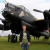
Hi all Here is my first finished new tool 1/72 Airfix Buccaneer S.2. I've built it as XN974 as she is today at the Yorkshire Air Museum. its built straight out of the box with a couple of scratch built aerials, and decals came from a Kits World sheet. It built up fine with no real issues, I had to use a couple of spots of filler in a couple of areas but that's more down to my ham fisted modelling skills than the kit itself. Been an engineer at YAM I did have access to real thing as modelling inspiration, and although its not a spot on representation of the real thing its close enough for me. I am going to change the serial number which is way too big on the kits world sheet and I'm going to add intake blanks and RBF flags at some point in the future. Enough waffle here's the pics Untitled by Scott Clayton, on Flickr Untitled by Scott Clayton, Untitled by Scott Clayton, on Fli Untitled by Scott Clayton, on Flickr Untitled by Scott Clayton, on Flickr Untitled by Scott Clayton, on Flickr Untitled by Scott Clayton, on Flickr And lastly yours truly with the model and the real XN974 Untitled by Scott Clayton, on Flickr Hope you all enjoyed ScottC
- 11 replies
-
- 54
-
-
T-34/85 Zavod 183 Mod.44 (6545) 1:35 Italeri The T-34 gave the German invaders something of a shock when they first encountered it during operation Barbarossa, their attempt at conquering the Soviet Union, and they were instrumental in reversing the tide through both their impressive performance and weight of numbers, due to their simple construction and the overwhelming industrial capability of the Russians. Even when the Germans were knocking on the gates of Moscow and Stalingrad, production was shifted lock-stock-and-barrel further east with barely a flicker, and in Stalingrad there are stories of fresh tanks rolling off the production lines and almost straight into combat. The simple design used tried and tested technology, together with innovative sloped armour that increased its effective thickness when hit in the horizontal plane. It was initially fitted with a powerful 76mm gun, but when this proved less able to penetrate the frontal armour of the Tiger, it was upgraded in 1943 with a bigger ZiS 85mm gun, which was equipped with a larger three-man turret that reduced the combat load on the crew, enabling the commander to concentrate more on the task in hand. It's diesel power plant gave it a good speed over most terrains, and as production ramped up there were over 1,000 produced each month, plenty to replace losses and more besides. The 1944 mod introduced a simplified new gun, improved crew layout, better sight and the radio moved into the turret to take advantage of increased space. The Kit This is a complete new tooling from Italeri, and shouldn't be confused with older toolings and collaborations, as it's a different animal. It arrives in a standard box with a fetching painting of the subject matter ploughing past ruined German armour, and inside are four sprues in dark green styrene, one in grey styrene, two lengths of insulated cable, a sheet of Photo-Etch (PE) brass, two rubbery tracks, decals sheet and the instruction booklet. The tooling is well-detailed, and as well as the rubber tracks there is also a full set of link-and-length styrene tracks, which should please almost everyone. What will also please many is the inclusion of a complete interior, even down to the engine compartment, the parts for which are on the grey sprue, so may have been a later addition. Construction begins with the lower hull, which has slots for the suspension, and circular holes for the drive sprockets, which are glued together from two halves, and fitted to a cone-shaped moulding with a cap inside to allow you to leave the idler movable. The suspension units are added to the inside of the hull with springs in diagonal housings, comprising two sections on each side, leaving enough room for the engine, which is next. You don't get a full engine, but the detail is plenty for the installation. The firewall has the engine top slotted into the back, and the aft of the engine with big fan is attached to the aft end of the top panel. The exhausts and large fan are glued in place, and the assembly is dropped into the hull, locating on tabs in the floor. The final drive housing is built up and dropped in behind the engine, and a set of ammo boxes double as a turret floor in the centre of the hull, with the driver's controls fitted at the front with some rather arm-chair style seats for driver and bow gunner. A scrap diagrams shows the correct position for the tools, controls and air bottles, after which the suspension and wheel set are glued in place, with nice detail on the wheels and their treaded rubber wheels, which are moulded-in. They fit onto swing-arms with stub axles in pairs that fix into two holes each in the sides of the hull to ensure the correct angle. The idler wheels are also added at this stage with their axle, two-part sprocket and hub cap holding it in place, and allowing it to rotate too if you're sparing with the glue. The final drive cover fits from underneath, with a note telling you to install parts 38A after adding the towing cable later, and then you can choose which style of tracks you'll be using. The rubber-band tracks are the simple option, and are moulded in a gun metal plastic that can be glued using super glue (CA). You can even forego painting them if you hate that sort of thing. The more complex option is to use the included link and length tracks, which have more detail, and will leave you with the correct faceted appearance where the tracks wrap around the ends of the runs. The top sections are each moulded as one piece, the bottom sections in two parts, while the curved sections are individual links, which are each made from two plates. More care will be needed for this option, but the results will be improved, and even more so with careful painting and weathering. The upper hull needs 11 small holes drilling out before you begin its assembly, mainly for the later mounting of fuel tanks, so get those out of the way before things get busy, or you might regret it. The louvers for the engine deck are inserted from the inside, and the hull is then turned over and detailed from the topside, with a central engine hatch and a big radiator box on top of the aft louvers, which has a two layer PE grille glued over its aperture after gently bending it to fit the curve of the box. Another two boxes with louvered parts are added to the sides of the engine deck, and a little tool box gets added to the starboard fender at the rear, then spare track links are assembled and lashed down with PE straps, with an additional length pinned across the glacis plate. The glacis plate also has the ball machine gun mounted and the large driver's hatch, which can be fitted open or closed and must have been a bullet-magnet when open. This is then fitted to the hull over the inner front panel, the turret insert is added, and three fuel drums are fixed to the hull sides along with some pioneer tools, more stowage, lights and shackles glued in place, with an overhead diagram showing their correct location. The two hull halves are married up, the front fenders added, and yet more barrels, this time smoke dischargers are added to the rear bulkhead skin, which is a separate part. The armoured exhausts are assembled and fitted to the apertures on the skin, and a central access hatch can be modelled open or closed. The whole rear bulkhead can be posed open on its hinge-points, and a PE lip is included on the brass sheet to give this a more realistic look. The exhaust pipe tips sleeve onto the main exhaust during the closing process, although the break-point looks slightly different from the pictures I have seen, so if you want to add a little more realism, drill out the ends of the pieces and add a collar near the end of the fixed part of the exhaust that comes out of the mufflers. The tip that is visible outside the tank already has a hollow end, which is nice. As yet the tank is turret-free, so the next steps rectify this with a full breech, ready rack holding 12 rounds, sighting equipment with gunner's stool attached, and the relocated radio gear, as well as a couple of periscopes in the roof. The commander's hatch has a periscope built into the front half, and can be posed open by gluing them into the ring in an appropriate position, then mating them with the cupola ring. This and the gunner's hatch are fitted to the top of the turret along with a couple of mushroom vents, various tie-downs and rails, while the mantlet with cover, two part styrene gun barrel and cheek armour are added during the mating of the top and bottom sections. These cast turrets weren't put together with extreme care, and the joints are sometimes horribly rough, so check your references and decide what they look like in the flesh. The turret has a nice sand-cast texture moulded-in, as does the mantlet, rear bulkhead and final drive panel. The barrel is split horizontally, so there's a seam to fix there, and once that's in place, the turret fits to the hull, locking with a bayonet fitting. The last job is to create the towing cables from the two insulated wires that are included in the box. You cut them to length, twist the strands as you slide off the insulation, then glue the styrene towing eyes to each end, draping them over the fenders and attaching them on the shackles as indicated. Markings There are four decal options from the box, all of which are painted Russian/Soviet Green, and one is over-painted with white winter distemper camouflage. Each tank has unit markings, as well as some additional markings and emblems. From the box you can build one of the following: 9th Guards Tank Corp, 2nd Guards Tank Army – Berlin, Apr 1945 64th Guards Tank Brigade, 1st Guards Tank Army – Pomerania, Feb 1945 44th Guards Tank Brigade – Yugoslavia, Spring 1945 2nd Motorcycle Tank Battalion, 1st Tank Corp, 2nd Polish Army – Jul 1945 The decals are printed by Zanchetti in Italy for Italeri, and have good sharpness and colour density. They are all either black or white, so there's no issues with registration either, as there isn't any! Colours are called out in Italeri acrylic paint codes, as well as FS numbers, which should be a help if you use another brand. Conclusion It's nice to see Italeri moving with the times, including PE and metal towing cables with their kits, and options to please modellers with different needs, such as the two track options here, and with this being a popular subject it should sell well, particularly with their wide distribution network. Highly recommended. Review sample courtesy of
-
Tempest Mk.V ProfiPACK (82121) 1:48 Eduard The Tempest was a development of the Typhoon, and might account for my endless ability to get their names confused. Originally called the Typhoon II, it was envisioned to solve any and all of the issues that bothered its designer Sidney Camm. The main difference was a much thinner wing which reduced drag and improved aerodynamics of the laminar airflow. The wings could accommodate 20mm Hispano cannons that packed an enormous punch, and lent itself to the low-level attack role that it was designed for. The engines intended to power the aircraft were the Centaurus, Griffon and Sabre IV, and initially the Rollf-Royce Vulture, which was terminated early in the design phase, leaving the three options going forward and necessitating substantially different cowlings to accommodate their differing shapes. The Mark V was split into two series, with the Series 1 having the Sabre II that had a similar chin intake to the Typhoon and many Typhoon parts, while the later Series 2 used fewer Typhoon parts and had their cannon barrels shortened so they fitted flush with the leading edge on the Series 2s. A few of the early Mk.Vs were used as test beds, while other marks were developed alongside it, such as the Mk.IIs with Centaurus engines and a cylindrical cowl; Mk.VIs which had a very short production run; the Mk.III and Mk.IV that used a two types of Griffon engine and didn't see service, and later the TT.Mk.5, which is where a lot of Mk.Vs ended their days towing targets in garish colour schemes. The Kit This is a complete 100% new tool, and shouldn't be confused with their older Tempest V that's been around for ages, and has some known issues with its tail. It arrives in the standard ProfiPACK box, with a brand new painting on the front showing the Tempest upsetting a V1 "Doodlebug" flying bomb, which was one of their tasks due to their speed and ruggedness, with stories of tipping them with a wingtip, and blowing them up from way too close with cannon fire. Either way it's extreme bravery on the part of the pilots that helped to reduce the toll on London from these new "vengeance" weapons late in the war. Following on the heels of their recent Spitfire, 109 and 190 toolings, the Tempest is packed with surface detail that is at the leading edge of moulding technology and skill. The rear of the fuselage is festooned with raised rivets that are correct for this series, and there are differing width panel lines, a number of types of fastener, with the detail extended across the whole airframe. The interior is similarly well detailed with pre-painted PE instrument panel and seatbelts amongst other parts, which you can upgrade further by purchasing the Brassin set that's available separately. Inside the box are five sprues of dark grey styrene, a circular sprue of clear parts, a sheet of pre-painted and nickel-plated Photo-Etch (PE), a set of canopy masks in yellow kabuki tape (not pictured), and the instructions with the profiles printed in colour in the rear of the booklet. Construction begins in the cockpit, which has a solid floor and framework sides, exposing the interior of the fuselage behind, which has been detailed by the designers inside the fuselage halves, showing great attention to detail. The seat, control column and rudder pedals are fitted to the solid areas, while the instrument panel and side consoles are suspended from the framework sides, which fit between the front and rear bulkheads, the latter being armoured and supporting the seat with a small framework of parts. The pre-painted belts are attached to the seat before installation, and more PE is used in the side consoles, resulting in a very neat and well-detailed cockpit. Before the fuselage can be closed around it, the interior area needs to be painted black (I prefer dark grey with a black wash), the simple tail-wheel bay needs constructing, and the complex radiator intake is built up from a substantial number of parts, which are shown with the correct order noted for your ease. You may want to pre-prepare some of the sub-assemblies in case there are any seams to fill in the intake trunking here. The final parts for the cockpit interior are fitted to the fuselage sides at this point, so that they show through the framework once it is installed. The lower wing is a single full-span part, and as you would expect the upper wings are separate parts that have the landing gear bay roof detail moulded in. The sides of the bays are added along with some detail parts in both bays, at which point the wings can be closed up and the whole assembly joined with the fuselage, and once the tail feathers with their separate rudder and elevators are fitted, that's the airframe ostensibly complete. The cockpit aperture is over-large, which allows an insert to be dropped in after it is fitted out with detail parts specific to this variant, the elevators and cannon barrel inserts are added to the wings, and it's then time to build and fit the landing gear. The tail wheel has a two part strut with Y-shaped yoke and separate two-part wheel that has an anti-shimmy groove moulded in, and two bay doors plus actuator for when the leg is retracted in flight. The main gear wheels have a large two-part balloon tyre with the Dunlop brand in raised letters on the side, and separate hubs for both sides to obtain the most detail. There is no tread, so hiding the seam on the tyre's contact patch will be easy, and if you like your wheels weighted, just sand a flat spot at the bottom. The gear legs are a single part each, and have a complex single-part retraction jack that extends inboard into the bay, with large captive bay covers on the leg, and smaller inner doors that fold toward each other on the centreline. A drop-down stirrup is fixed to the underside of the fuselage for the pilot, a pitot probe added to the wing, and a bunch of PE fish-plates are added to the transport joint at the rear of the fuselage, which were to correct a structural weakness in these early airframes that utilised some of the Typhoon parts. On the topside the two-part canopy is attached, with the opener having a styrene insert for added detail that latches into the track, with a whip-antenna just behind its furthest point when open. The four-bladed prop is a single part that is attached to the back-plate and spinner cap, then glued to the front of the fuselage along with a pair of exhaust stubs, which don't have hollow tips. There is a resin set that adds more detail and includes hollow tips that we'll be reviewing later, once we've finished drooling over this. The canopy masks also include a pair of dots for the tail wheel, and tread-plate masks for the root of each wing that will be useful to cover up an initial squirt of black before you begin painting the main colours. There aren't any weapons shown in the instructions, but they are available on the sprues in the shape of eight unguided rockets with moulded-in rails of the simplified and more traditional early types, plus eight separate tail fins, enough for one set of rockets. Markings There are six decal options included with this ProfiPACK edition, and due to this aircraft's service and duties, half of them are shown in D-Day markings, with the familiar black and white invasion stripes that stopped them getting shot at by their own people. The sheet is combined with a set of stencils that are also being sold separately for those with the Overtrees that can't get enough of their Tempests. Decals are by Cartograf, which is a guarantee of good registration, sharpness and colour density, with a thin gloss carrier film cut close to the printed areas. From the box you can build one of the following: JN766, No. 486 (RNZAF) Squadron, RAF Station Castle Camp, Great Britain, April 1944 JN751, Wg Cdr Ronald P. Beamont, DSO, DFC & bar, CO of No. 150 Wing, RAF Station Bradwell Bay, Great Britain, April 1944 JN755, No. 3 Squadron, Newchurch, Great Britain, May 1944 JN751, Wg Cdr Ronald P. Beamont DSO, DFC & bar, CO of No. 150 Wing, Newchurch, Great Britain, June 1944 JN763, No. 486 (RNZAF) Squadron, Newchurch, Great Britain, June 1944 JN765, No. 3 Squadron, Newchurch, Great Britain, June 1944 Conclusion If this builds as well as the 109 or Spitfires from Eduard (and I suspect it will), it will be awesome. The kit is just packed with detail, and if you still want more, there are a whole host of PE and Resin sets that we'll be looking at in the near future. What an end to the year for Eduard! Eduard have shut down for the Christmas period at time of writing, and will be back on the 7th of January 2019. Overtrees (82121X & 82121-LEPT) If you have one of these new kits but wanted to do another decal option in addition, or have an aftermarket decal sheet in mind, you'll be pleased to know that you can get just the sprues from the Eduard site, and if you want to add some detail, you can also get a set of Photo-Etch to go with it. They arrive in a white box with a sticker on the end, with all the styrene in the one bag, and the clear parts bagged inside that for their safety during transport and storage. The Overtrees as they're called can only be bought directly from Eduard, so click on the button below to pick up yours. You can also download the instruction booklet if you don't already have one from the main kit page. Overtrees Kit Overtrees PE Review sample courtesy of
-
 Hej! Britmodellers, having finished my up to now stölth Hammer of Thor for Modellfan 10 2018. So for all Roumormongers: Specialhobby had already a Article Nr. for the JA at the Nuremberg Fair, but they decided then to go again with Tarangus. This is my early testshot handed to me in Prague before that decision. I was free to choose the version, because no decals were ready too at that time. The shot was very, very good, i only polished the prototype canopy and you all fans will have a lot of fun with this, because there is not a lot to complain even for special Specialists on the Viggen Cheers, Tom
 -
Here's my build from the 'P-51D dedicated GB', build thread over there, but not much to say or see really. Only my second new tool Airfix I've done and it is a cracking little kit, perfect Mojo restorer if needed! Only problem was the un-usable Aerial mast, which I did a couple of attempts at scratching it, turned a little too short and is leaning rearwards for some reason, but I'm just gonna leave it. Used the markings from the Xtradecal sheet X72228, for a 3 Sqn RAAF machine, KH716 CV-P based in Italy 1945. Paint was AK Interactive 'Extreme Metal' Aluminium, airbrushed with no issues straight from the bottle. Rest was done with Vallejo and Humbrol Acrylics. A bit of Vallejo Satin Varnish was used to dull the gloss of the decals down a bit and randomly brushed on over the airframe to try to vary the finish. A light weathering was dry-brushed on, the 'chipping/faded' effect on the anti-dazzle panel was to hide my mistake fuselage join!
- 10 replies
-
- 25
-
-
-
Hi all, Our IPMS group was invited to show our models at the local RAFA's RAF100 event. With a week to go I realised I needed more than Spitfires and one Sunderland. With a week to go, I grabbed this starter set JP from the stash, mainly on the grounds that a single colour would be quicker...obviously red not a brilliant choice. I also built a Frog Meteor during the week, as well as completing the Spitfire Vb in the Classic Airfix GB. Built in flight for ease, hence the small 1/16" square hole in the underside for the stand. The RAFA and their guests were impressed and complimentary about our models, although various people kept pointing out rather obvious gaps in our selection...we also got to speak to two WW2 pilots, one whose time was spent flying rhubarbs and circuses in Spitfires, whilst the other had chosen Thunderbolts over Spitfires in Burma. He said that when he was given that choice, he fancied something bigger and tougher around him! Cheers Will
-
We have just received conformation that the new tool Hasegawa 1/72 F-35B is on it way to us! Stock is limited however so don't miss out! Hasegawa 1/72 F-35b
-
Here's my third completion for 2018, Hasegawa's new tool H8K1 Emily: I bought the H8K2 when it was released last year; when they released the H8K1 some months later I had to get this one as well - to be honest if I'd had the choice at the outset I would only have bought the H8K1 as I prefer 'clean' aircraft unemcumbered by the radar array that, for me, spoil the look of the later versions of the Emily. It's the same kit with a couple of different sprues including a new nose section and with the majority of the cannon armament of the H8K2 replaced by what appear to be VGO machine guns. The kit transfers were used to represent an aircraft of the 802nd Flying Group based at Rabaul in 1942 - these aircraft were initially used alongside the older Kawanishi H6K Mavis flying boats and undertook some seriously long-range penetrations including attempts to launch bombing raids on Pearl Harbour and Northern Australia. As with the H8K2 kit I built earlier this year the undersides were finished in Alclad Semi-matt Aluminum with the doped fabric parts represented using Citadel Runefang Steel; the uppersurfaces using Colourcoats ACJ01 IJN D1 Deep Green Black, with the doped fabric surfaces painted using the same colour mixed with a little ACJ18 IJN Interior Olive Green. One thing I did differently this time was to spray the leading-edge ID markings in Colourcoats ACJ19 ID Yellow rather than use the kit transfers, as I had a little trouble getting them to conform last time. The floats were rigged using Infini Lycra thread which was also used for the r/t antenna wire. Finally, here's a couple of pictures of her with her younger sister: Cheers, Stew
- 11 replies
-
- 30
-