moaning dolphin Posted August 22, 2016 Share Posted August 22, 2016 Very nice indeed, note for next shopping trip.....Microsoft chisel... of course all the pipes I said were metal colour are in fact same colour as the head. A bit of brain fuzz clouded my memory 😃 Link to comment Share on other sites More sharing options...
Ex-FAAWAFU Posted August 22, 2016 Author Share Posted August 22, 2016 Mine is made by an outfit called Master Tools; I have a square nosed one serial no 09924, and the rounded one is 09926. I got them at Yeovilton show about 6 months ago. Like many specialised tools, I don't use them very often, but whenever I do they are simply the only thing that will do the job. Superb. 1 Link to comment Share on other sites More sharing options...
Benbow Posted August 22, 2016 Share Posted August 22, 2016 Partly FOD protection, but mostly anti-icing; the things that look like white chevron shapes were a system for distributing anti-icing gunge whose name escapes me, but which stank hideous! Think it was"TKS" glycol anti-icing fluid. 1 Link to comment Share on other sites More sharing options...
Ex-FAAWAFU Posted August 23, 2016 Author Share Posted August 23, 2016 You're right; it was Link to comment Share on other sites More sharing options...
TheBaron Posted August 23, 2016 Share Posted August 23, 2016 Engrossing work on that rotor head Crisp, and a very lucid outline of the structural components. Even I'm starting to understand how your mount worked You'll be adding scale bits of blue tape at the weathering stage I guess.... Link to comment Share on other sites More sharing options...
Pete in Lincs Posted August 23, 2016 Share Posted August 23, 2016 Forgive my ignorance, but enquiring minds need to know.... c) release the rotor brake;d) position the 4 folding blades in the right position (centre them on all the hinges explained before, essentially);e) turn the head so that No 1 blade is pointing straight back down the spine - it takes the shortest route, so can move in either direction;f) re-apply the rotor brake; Let the clutch out? Which pedal is that? Just wondering, The hyd system turns the head? (Aircraft microswitches and hammers. A natural pairing) Link to comment Share on other sites More sharing options...
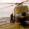
hairystick Posted August 23, 2016 Share Posted August 23, 2016 That is a slightly disturbing position for the "rescued" person to be winched up in. 3 Link to comment Share on other sites More sharing options...
wyverns4 Posted August 23, 2016 Share Posted August 23, 2016 That is a slightly disturbing position for the "rescued" person to be winched up in. Well, it is the Navy... Christian, exiled to africa 3 Link to comment Share on other sites More sharing options...
Ex-FAAWAFU Posted August 23, 2016 Author Share Posted August 23, 2016 That is a slightly disturbing position for the "rescued" person to be winched up in. Pretty standard position in the double lift harness. The head of thevictim - I mean grateful rescued person - us higher than this makes it appear. For details, ask markdipxv711. I was just the trained monkey up front; he was one of the poor buggers who (ahem) went down on the end of the winch wire. 3 Link to comment Share on other sites More sharing options...
Ex-FAAWAFU Posted August 23, 2016 Author Share Posted August 23, 2016 Forgive my ignorance, but enquiring minds need to know.... c) release the rotor brake; d) position the 4 folding blades in the right position (centre them on all the hinges explained before, essentially); e) turn the head so that No 1 blade is pointing straight back down the spine - it takes the shortest route, so can move in either direction; f) re-apply the rotor brake; Let the clutch out? Which pedal is that? Just wondering, The hyd system turns the head? (Aircraft microswitches and hammers. A natural pairing) Yes, the Utility hyds turn the head; if you look at post 92 on page 5, you will see in Moaning Dolphin's page from the manual (roughly enter left) a "hydraulic mother - 2-directional", part of a "positioner unit". You would only ever do this in accessory drive ("Acc Drive") - i.e. with No 2 engine shut down or at idle (and thus not driving the blades) and No 1 driving the accessories gearbox but not the blades. [i'll explain that at some point, too!] 2 Link to comment Share on other sites More sharing options...
Ex-FAAWAFU Posted August 23, 2016 Author Share Posted August 23, 2016 Just remind me, I did say that I was giving Ark Royal a break because I could only take so much tiny detail...? Hmmm. Working on bits of the head - the solid bits (i.e. before looking at any wiring). I have finished all 5 of the pitch change links (as per yesterday - post 124), and dabbed on a bit of paint just for a look. Happy with that. Then I started on the blade roots themselves. Just to remind you, the actual thing looks like this: Herewith a before (top) after after (bottom). Getting there... 6 Link to comment Share on other sites More sharing options...
moaning dolphin Posted August 23, 2016 Share Posted August 23, 2016 Nice work on those cuffs, its starting to make a difference! [i'll explain that at some point, too!] Will that be at the point when you are scratch building the gearbox?? 2 Link to comment Share on other sites More sharing options...
Ex-FAAWAFU Posted August 23, 2016 Author Share Posted August 23, 2016 Nice work on those cuffs, its starting to make a difference! Will that be at the point when you are scratch building the gearbox?? If so, you have my permission to drive to my house & shoot me! 2 Link to comment Share on other sites More sharing options...
Pete in Lincs Posted August 23, 2016 Share Posted August 23, 2016 Dolphin, grab his stash while you're there! 7 Link to comment Share on other sites More sharing options...
andyf117 Posted August 23, 2016 Share Posted August 23, 2016 (edited) Content withdrawn - I will NOT be threatened by a moderator, simply because I queried the actions of another... Edited June 27, 2020 by andyf117 Link to comment Share on other sites More sharing options...
hendie Posted August 23, 2016 Share Posted August 23, 2016 nice work. for that lovely spaghetti nest of hoses and gubbinses, you might want to look into 1/48 scale valves. I believe True Details do a set in 1/48 - I used a few of them on the Wessex build (http://www.britmodeller.com/forums/index.php?/topic/234971153-wessex-hc2-a-dauphins-stablemate-520-days-later-its-finished-why-yes-it-is-indeed/?p=2007885 - see about halfway down the post) You get about 120 or so valves in a set, available from Hannants... https://www.hannants.co.uk/product/TD48557 ... c'mon, you know you want to 1 Link to comment Share on other sites More sharing options...
Ex-FAAWAFU Posted August 23, 2016 Author Share Posted August 23, 2016 Ooh, brilliant; guess who has just spent a couple of hours of unsatisfactory experimentation...? That should make things much neater 1 Link to comment Share on other sites More sharing options...
71chally Posted August 23, 2016 Share Posted August 23, 2016 Partly FOD protection, but mostly anti-icing; the things that look like white chevron shapes were a system for distributing anti-icing gunge whose name escapes me, but which stank hideous! Now that is something I genuinely never knew, always wondered what the chevron 'markings' were for. Link to comment Share on other sites More sharing options...
Martian Posted August 23, 2016 Share Posted August 23, 2016 I think Albion Alloys aluminium tubing might be your friend for doing the valves. Its what I tend to use. Martin Link to comment Share on other sites More sharing options...
Ex-FAAWAFU Posted August 24, 2016 Author Share Posted August 24, 2016 (edited) Now that is something I genuinely never knew, always wondered what the chevron 'markings' were for.John Chartres' 'Modern Combat Aircraft 18; Sea King' (long out of print, but widely available - & useful for this build cos it only goes up to HAS5) says that the barn door initially came in purely as a physical barrier in front of the intakes, to stop chunks of ice that break off the nose from being ingested. The TKS anti-icing-fluid-dispensing stripes "were added because the shape of the 'barn door' tended to increase the build up of ice on the forward upper slope of the fuselage".New one on me, but I see no reason to doubt him. The barn door slightly reduced airflow to the engines; it made about 2% difference in power (from memory). In the tropics in 1988, when we reckoned airframe icing was a very remote possibility but power was becoming an issue, we took them off for a while. The Sea King's icing clearance was pretty decent. The dodgy band (0 to -10; below that the stuff hitting the airframe tends to start as ice rather than water so actually accrete a bit less) was well covered, and we routinely flew in those conditions. The big no-no was flight in freezing rain, which was explicitly forbidden in the Aircrew Manual; if that was even forecast we shut down and went to the bar. It can build up so fast that you rapidly take on the aerodynamic properties of a brick. I recall reading (but can't find) an "I learned about flying from this" article in one of the flight safety mags written by an HAR3 driver from Lossiemouth who had briefly found himself in freezing rain. His blades started to ice up and he plummeted earthwards out of the cloud, barely under control. The warmth closer to the ground was enough for the ice to break off and he landed safely, but terrified. Not nice. Edited August 24, 2016 by Ex-FAAWAFU 6 Link to comment Share on other sites More sharing options...
CJP Posted August 24, 2016 Share Posted August 24, 2016 great to see another one of your detailed models evolve and the stories about the real life situations in the post are very interesting CJP 1 Link to comment Share on other sites More sharing options...
Ex-FAAWAFU Posted August 24, 2016 Author Share Posted August 24, 2016 (edited) You know how it is when you get a day when you are wrestling with a particular problem, but after several hours of knowing exactly what you are after but never quite nailing it, you have to call it a day and go away to think again? That was me yesterday - and the crowning moment was when the thing I had been working on for a couple of hours pinged off into the gaping maw of the carpet monster. Time to stop. Sometimes when you have a day like that, when you come back to try again suddenly it all starts to hang together. I am working on the droop stops - Hasegawa's amorphous flattish blobs. When Hendie & Martin started talking about valves and Albion Alloys slide-fit tubes, a light bulb went on over the top of my head. This is where I am trying to get: ...the W-shaped thing marked G-42 is the droop stop. There is more of it out of sight in this pic, but for now the W shape is the thing. Slide fit tube. Measured the Hasegawa Amorphous Flattish Blobs (HAFBs for short) on the un-tweaked rotor head of my AEW2a kit. And cut 5 identical short tubes: Then some quick measurement and cutting on the inner, thinner rod, some swift bending, and... [White plastic rod simply for illustration; this will probably be soldered once I find some brass rod of suitable fatitude] And finally shown next to the AEW2a's HAFBs: I think this is going to work! More soon Crisp Edited August 24, 2016 by Ex-FAAWAFU 9 Link to comment Share on other sites More sharing options...
Ex-FAAWAFU Posted August 24, 2016 Author Share Posted August 24, 2016 (edited) v2.0 - better scale. And, having finally reached a prototype that I am happy with, I present one droop stop factory: 4 tubes (plus one longer one from which to cut the fifth - the original having been consumed by Mr Carpet 5 sections of rod 1 length of 0.2 nickel silver rod (I LOVE this stuff, as readers of my Ark build already know) Plus 1 section of 0.26 wound guitar string (courtesy of Ernie Ball), which will go towards making the springs that sit behind the section you have already seen. Now all I need to do is get out my trusty soldering gear and put them together... More soon Crisp P.S. The very sharp-eyed among you might have noticed that the rotor head has already acquired its first oil pipes. Easy ones first; 5 running from the central reservoir to the damper / flapping hinge area. Edited August 24, 2016 by Ex-FAAWAFU 6 Link to comment Share on other sites More sharing options...
moaning dolphin Posted August 24, 2016 Share Posted August 24, 2016 v2.0 - better scale. (In a Churchil the Bulldog type stylee!) "oh yes" 1 Link to comment Share on other sites More sharing options...
hendie Posted August 24, 2016 Share Posted August 24, 2016 oooooh - nice work Crisp ! Very impressive. Link to comment Share on other sites More sharing options...

Recommended Posts
Create an account or sign in to comment
You need to be a member in order to leave a comment
Create an account
Sign up for a new account in our community. It's easy!
Register a new accountSign in
Already have an account? Sign in here.
Sign In Now