

Stickframe
-
Posts
642 -
Joined
-
Last visited
Content Type
Events
Profiles
Forums
Media Demo
Posts posted by Stickframe
-
-
Hello gents -
Am pleased to report that I'm making some discernable progress:

As this will need some landing gear, I built up a bay for it to squeeze into, which allowed me to push ahead a bit more with the cockpit
I managed to finish the floor and add a console, and on the underside:
A nice and tidy fit. The ugly chewed up plastic on the left, well, the price a guy pays when designing as he goes - I'll clean it up later. There are relatively few straight pieces of material in here, so lots of filing, sanding and reworking. I had some pictures of this area, showing the wheel in the up position - and, not to worry, I deleted them, so, just imagine a nice fit! 😄 and what it looks like as whole:
One goal was to try and keep or at least not detract from the basic F1 car lines, so, adding the landing gear bay required some head scratching. To do this, I would add a piece or two on the underside, then essentially mirror them on the inside - I'm working on the doors now. The body work is thin styrene over internal ribs.
The rear poses its own problems:
Like the front, I'm adding room for bays that will fit the landing gear and those huge tires under the body. I'll add in some hydraulics, like the ram in the front, to suggest that this gear will tilt inward when flying about. The body work and bay doors is requiring plenty of fussy work, but it's coming along.
thanks for having a look
Cheers
Nick
-
 7
7
-
-
It's fun to see how you are conceptualizing, cutting up, and pulling all of this together. The Jaguar is a cool idea - and I'm curious to see with what you do with/make the spoon top work.
Cheers
Nick
-
 1
1
-
-
@Agent K, thanks very much. For a while now, I've been taking pictures of projects outdoors - on the up side, the colors are crisp and the light/shadow relationship has to be right 😄 the sun is where it is, and the project is too! on the not up side to taking pictures outdoors - well, natural light seems to feature a relentless measure of honesty - that is, if you have some mismatched or skipped some paint, it will be remarkably obvious, and the same goes for the build. If something it not flush and it is supposed to be, it will indeed cast a shadow. These challenges aside, I'm going to stick with outdoor pictures! thanks again-
@Jim Wasley, you know, this did take some work. But, there was enough of it to go around between the actual dio, figures, and vehicles that it was easy enough, or to be more clear, the best way to protect my sanity 😄 was to skip between them - maybe a week on figures, the next on the base, and so on - thanks
@Andy H, thanks very much - I appreciate hearing that. You never know if the idea actually works until someone (the builder's opinion doesn't count! 😄) actually says what they think thanks
Cheers
Nick
-
1
-
1
-
-
Hello gents, thank you, and I'm glad this passes the collective "eye test!"
In the last few years, I've found I enjoy taking pictures of the final almost as much as building it! I really struggled through the first few efforts....just not very convincing.
These are not photo shopped, but I use a generally similar process. Each photo is resized, then using a free online tool called "Photoscape X" I make a cutout of the subject, followed by a super high tech step - I import a background that I like, and the picture into....Powerpoint. Once in PPT I enlarge and reduce pics to work together - that is making sure shadows are basically going in the same direction, and that there is a believable vanishing point. This is a slow process, but having done it a few times, and like the result, I don't mind. I don't use any picture corrections or filters ever - the picture of the subject represents the model as built.
Ok, thanks for having a look!
Cheers
Nick
-
5
-
-
A Dyson???? how hurtful! Model builders have feelings too!! 😄😄
I'm still working on the calculations for defying gravity, but I'm getting very close, I think my findings will be pretty big.
As I'm struggling a bit with gravity, I began thinking about horizontal control - how can I make the vehicle turn or not turn under power? so a guy went ahead with some basic calculations:
The results are clearly obvious enough 😄 to work, this will need twin tails/rudders to perform. So, went about making up some pretty sassy tails:
As a result of my rigorous analysis (🧐😄) I located the bases for two tails, one on each side, just inside the engines. Naturally, these needed to be canted outward, at a 20 degree angle - what a treat!
As this is supposed to be an overlander, the space between the tails is for gear!
To work through this I made a simple, but very useful template:
Perfect! ideal for laying out the tails and setting the base angle too!
But, to get this done, some remarkably ugly assembly:
Hmmm, while these are giant at 1/20 compared to what you might see in 1/48, their frame and inner ribs are absolutely tiny.....this picture makes them look huge. They are not.
How much simplicity and beauty? All of it! 😄......and, with some skin:
Not bad. This was some slow going, but, I now have two almost matching tails. I'll scribe the rudders into the surface. Believe it or not, I pondered making each piece with two parts, tails and rudders....I was then hit by a tsunami of common sense! No, one piece with some scribing will be just mint!
Thanks for having a look -
Cheers
Nick
-
7
-
-
What a great build - absolutely beautiful - 😃
Cheers
Nick
-
Hi gents,
ok, I guess we're moving! or tying to make this move!
@rockpopandchips, yes! with my complete lack of knowledge of aviation, and well, shaky understanding of physics, we should be good to go! of course it will fly! 😄
@PeteH1969, ha! a glorified Fiat eh??? 😄 a perfect base for this!
@Pete in Lincs, yes! the goal is to demonstrate convincing realism! that is, to make it look close enough to be credible!
@Hunter Rose, thanks! yes, that's the plan! I'm trying to get the basics done and at least somewhat believable, but as @Pete in Lincs, there is that little problem of going in reverse....???hmmm - well, as this is air ride, maybe maybe it pivots in place?? hmm, sort of like turning a tank? lock one track and turn the other?? but with thrust???🧐😄 Maybe a big fan on the front??
@Peter2 yeah, about that....😄 In case you need more proof, think of the treasure chest of etch, small brass bits, resin bolt heads and other gems hidden in plain sight directly beneath the workbench! I know they are there somewhere!
@Thom216, thanks! let's see how it goes!
And on we go - first up, well, only having an idea for this, well, it seemed like a good idea to just keep building:
So, what you see here, obviously, 😄is the rear anti gravity device for lift, and two engines for thrust! The majority of examples of these vehicles I saw placed four anti gravity devices around the vehicle, one on each corner. But, it occurred to me that by doing this, you are just adding more places where the antigravity unit could rip from the hull - especially in the back which would likely be more heavy than in the front. So, I made up one bigger device, and placed it in the middle, attached to the monocoque! perfect! leaving room for engines in the air ducts.
The idea, being the bigger anti-g unit is doing the heavy lifting, merely defying gravity that is! As this would be a herculean task, the thrust would require less force than if they were also being used to, uh, defy gravity, so smaller engines of some kind go on each side -
et voila! these F1 cars prove a nice base for this! I have carefully cut up a lot of the red plastic, but it's coming along. As for the anti-g:
So I did some quick calculations and figured that this should be about right! or, well, it looks a lot like what it's supposed to, and it fits! Thankfully, I have plenty of left over parts!
And where it sits today - so, on we go!
Cheers,
Nick
-
12
-
1
-
-
@dnl42, I hear you on this. The RFI pictures are like final exams - let's (literally) see how you did..... 😄 I've come to think of final pictures as the last step in the build, and enjoy pulling them together. I'm willing to "pretend not to see" a few things 😉, but others, well, add a glass or two of wine, or a cup or two of coffee 😄 and out comes the knife! thanks for leaving the note!
@Pete in Lincs, hi Pete, yes....you know, having now built a few projects, the prospect of digging into something that is essentially done is a bit less daunting, and well, crucial! 😄 Somewhere along the way I came to realize that if I managed to get the build this far, well, even if I cause some heavy damage during the repair, chances are pretty good that I'll be able to figure out how to fix it, so why not???
@keefr22, hi Keith, I think you summed this up pretty well! I suppose that problems like this sort of creep along, and while somewhat evident, it becomes easy enough to trick yourself into thinking it's ok, and then....RFI pictures, and looking at the build more carefully 🧐....well shoot! time to fix this! thanks!
@busnproplinerfan, hi Bus, well, yeah....it was wrong. The root cause of the problem was two fold. First, the kits would have the hood/grill assembly floating in the front, and attached in the back, via two "arms" that connect the fenders to the frame rails. Next, by reworking a lot of the chassis and engine components, the already weak connections get weaker - I wonder how it would go together as a stock kit? anyway, thanks -
Cheers
Nick
-
2
-
-
Hello gents,
I just finished a project that I really liked, but realized it was the latest in a string of the same subject, and concluded that a guy needed some variety in model building. So decided to get after a concept I've been pondering for a while. As you can see below, I thought it would be a good idea to start with a Ferrari F1 kit that has been sitting unbuilt for far too long:
Step one was to cut this kit in half so that I could make it into a two seater and so far so good. As I am not a follower of current thinking on anti-gravity cars, well, went ahead and looked at several conceptual art and design sites to see what the prevalent thinking on this subject is - and well, some ideas were pretty cool. I saw a few versions that were based on F1 cars (though from the images, I really can't say how they would be powered? or why they "boasted" really long noses?), but none caught my eye, though I suppose I will include some of the current vernacular of thinking on the subject 😄
I noticed a recurrent theme of what turned out to be rings of spinning, super conducting ceramic and a series of solenoids located where four wheels would otherwise go, but mounted horizontally. So, I suppose I will have some of those.... Evidently these devices create a magnetic field/force that would serve as the source of power (force?) used to elevate an object off the ground - aka making it gravity defying.....well, there you go. I am going to go with it, as I want to build something new to me. What I didn't notice in these concepts was a consistent source of thrust or propulsion to allow for horizontal movement, so I'll make something for that - I don't want an anti-gravity vehicle that just floats 😄.
As I pondered all of this I thought back to my days in college...and trying to pass physics, and remembered the formula that solves everything: force = mass x acceleration 😓😥 Aside from those being awful days, I took from them that lifting something, anything, requires the exertion of energy, and that well, gravity is not as easily defied as someone using graphic software might suppose, hence my idea of an overlander - something of a low level/elevation craft, that can be lifted and can scoot around, But, not something that would instantly spring upward and zoom about at great speed - I guess each of those vehicles would have one heck of a robust power and fuel source? - Not mine - it will have enough power to get some lift and zip around, but I don't think any of the teen series of fighters would have much to worry about from this - maybe more like an old Toyota FJ 45 or Chevy Blazer?
I'm thinking about adding a utility bed of sorts, for hauling some gear - who knows? maybe these are used for patrolling remote places? or research? whatever the case, I think it will be more interesting, maybe a streamlined version of an Ian McCue air ship? I don't know just yet -
Ok, thanks for having a look
Cheers
Nick
-
12
-
-
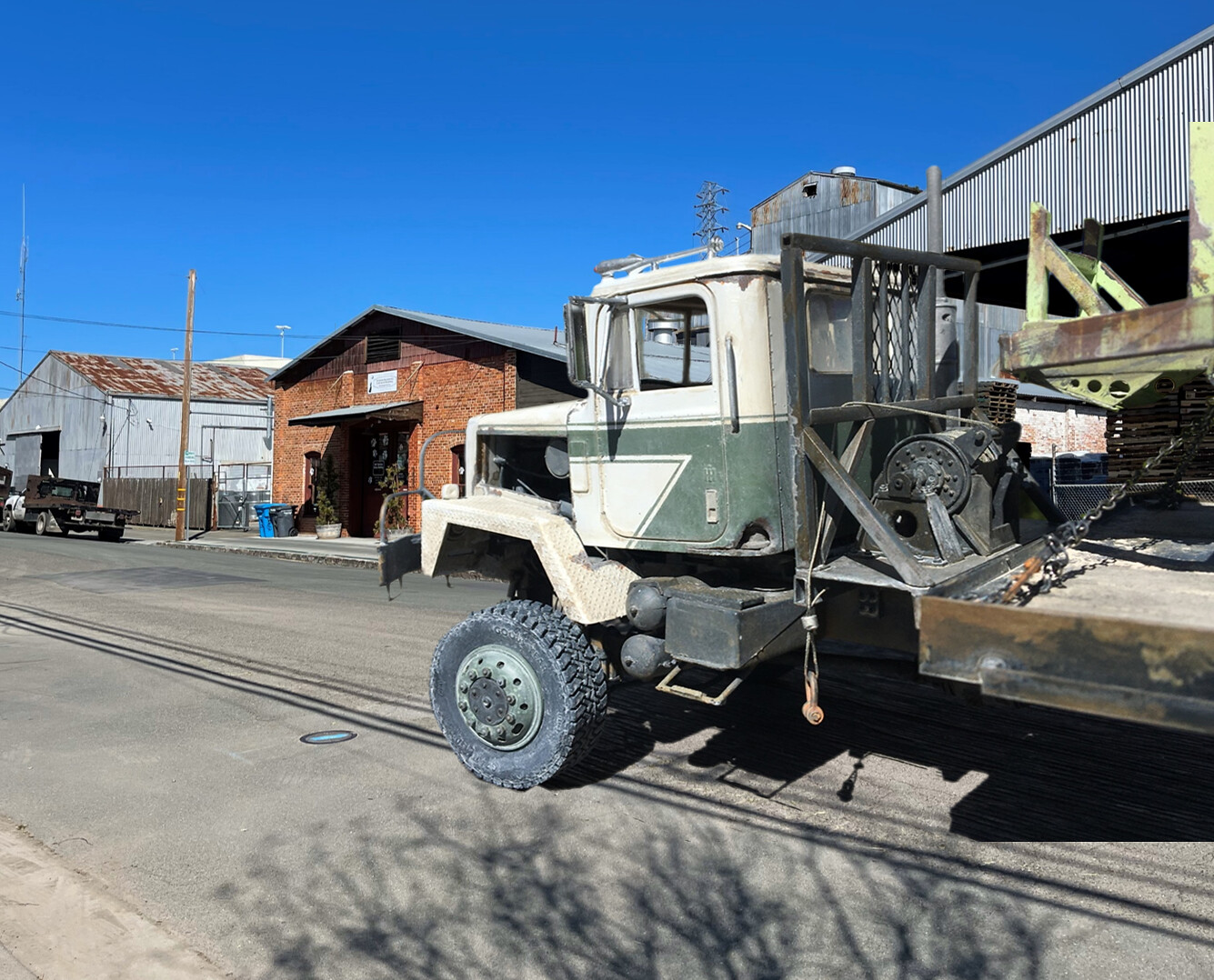
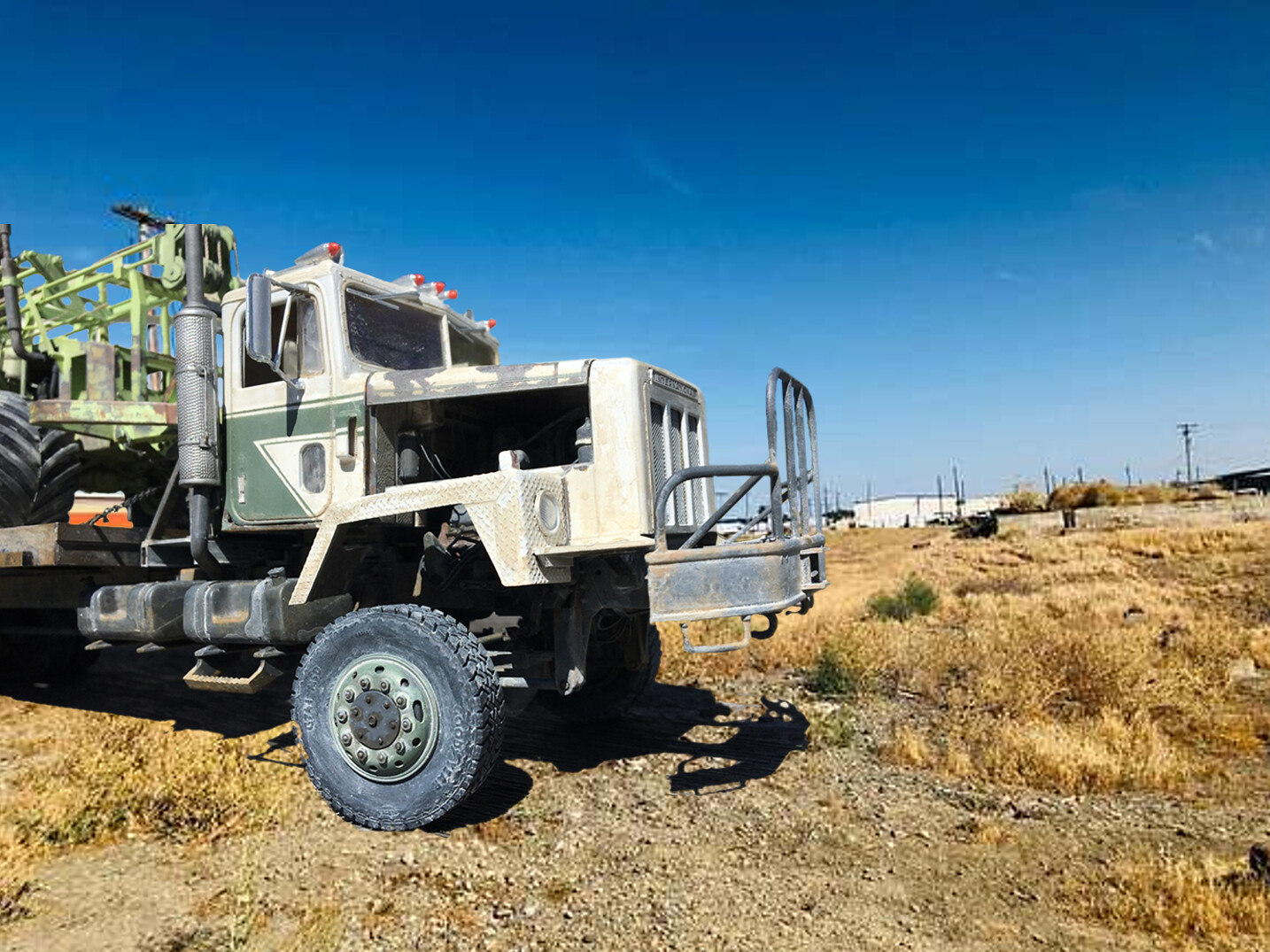
Hello gents,
It's time to call this project done. It is an International Paystar 5000, which I converted to 6x6, extended the chassis, made a winch and rack, and flatbed and ramps for. The project also includes a scratch built all terrain geotechnical drill rig chained to the bed.
If you're interested, here is the build log
It turns out yesterday was quite sunny, so I took the model outside for lots of photos:
I include the two pictures above because this project includes a fair amount of interesting details, in this case the front suspension and dual steering, which usually go unnoticed! But, I like these, so posted them 😀
The goal of the project was to build a tough old truck hauling an equally well used piece of equipment. Building the drill rig was fun, as I know nothing at all about these in real life. The truck became more of a technical challenge as I am more familiar with them, but needed to design it to accommodate the drill rig.
In retrospect, there are few things about the truck build I should have done differently. Starting with the suspension. I built my own leaf springs/brackets and so on for the front, which worked out really well. But, for the back I used some kit parts for a walking beam suspension - this was a mistake, as the parts were (evidently) somewhat warped, which of course I noticed, but didn't worry about it. Well, as you can guess, I spent far too much time fooling around with it to get it so sit level, and should have just built my own.
Next, the cab, and specifically the hood. The mounting points on the kit part were/are not solid/clear. I should have just just cut them off, and made my own. Should you go back to the build thread, you'll see I spent way too much time dealing with this, all the way up to the end of the project...😄
I really enjoyed the weathering process, which I hadn't done in a while.
Finally, just for fun, the photo grouping below. I don't use any photo filters/processors etc, on any photos, but these have some pretty strong saturated color right out of the camera. I took these images the day before I took the finals, used above. As these were taken the day before the others, you can see the cab and hood were not seated correctly:
OK gents, thanks for having a look - time to find a new project!
Cheers
Nick
-
20
-
-
As we are all model builders, well, we get that: some parts take hours and hours to get resolved, and you never see them....and; some parts take hours and hours, don't look right, and, you can easily see them.....
On Friday I went about finishing the model, making last minute paint touch ups etc,, because as it turned out, yesterday was glorious and sunny, a perfect day to take a model outside for some photographs, which is exactly what I did - and what a treat it was - walking down my neighborhood street with model in hand, looking for flat places that might serve as good bases for this task! It turns out there are several relatively squat bollards here and there, and they are ideal for this purpose, so I went about my business, taking lots and lots of photos! Oh the good times - getting bright colors, strong shadows, and, talking with many of the walkers, joggers, and cyclists making their way past - a fantastic celebration of how nice the model turned out! 😎 😀
So, once I had many photos, back home I went to resize, crop, and cut out - perfect!
Except, along the way, I couldn't help but be distracted by exactly how bad the cab and hood looked! - what the???? I already spent a lot of time "fixing this"...more than once! So, after some wine with dinner, I concluded that I could not abide a screwed up cab - and, out came the knife, some force, and once again, off came the cab and hood!
As you can see on the left, I apparently chose to pretend to not see exactly how bad this looked.....(but, you can also see the chains are in tension! 😃)
Now as you can see on the right, it is now better, or as good as it will be!
So, back out into the neighborhood I went this morning with the model, and took lots and lots of photos, and again, chatted with friendly passersby. Then spent the afternoon, picking images to use - lol - good times.
I'll probably post the finished model in RFI later today or tomorrow,
Cheers
Nick
-
5
-
-
@dnl42 - oh, thanks for including the link! I'll check it out - I hope you're not setting me up for an impossible project! 😁
Cheers
Nick
-
Hello gents, and glad you approve! Mood lighting eh? 😄 That's a good enough story for me!
Meanwhile, it appeared that this was about done, well, in some ways yes, and in others clearly no.
First up, how about attaching the cab? how hard could that be? well, pretty hard - as I cleverly added hoses to the motor, cut up the chassis and whatnot, well, getting the cab firmly in place was a challenge. In addition to my self imposed "challenges", it turns out the cab location is governed by the exhaust stack on the back, and big air cleaner assembly in front. Not to worry though, none of it lined up - and cutting, rebuilding, and repainting was involved.....
And here it is - attached! and while I was at it, fixed up some of the streaking grime on the paint I didn't like.
So with that done, I went about finishing several other tedious tasks which I wont regale you with - and will instead jump to the truly evil task - making four chain stretchers. This turned into an awful task, which took over two hours to complete!
What is a chain "stretcher"? well it's a mechanical device used to apply tension to chains when they are use to hold things in place, like a drill rig to a bed, which is what I decided to do.
And what do these sassy, evil bits look like?
Here's one in the open position - and below:
In the closed position - oh what a treat - a total of 9 PE parts, plus, two brass rods each. And yes, they are considerably smaller than these pictures suggest.
While these are pretty nice, I have no idea if they are intended to be operable, but, mine are. Why? well, my plan is to mount the drill rig on the bed, and hold it in place with chains which attach to D rings on the bed - but, I figured out pretty quickly that it would be difficult if not impossible to insert these in the chains in the closed position and keep the chains in tension while doing so - hence, I built them to be operable.
While hard to see, there are two moveable D rings installed in the corners of the bed (front and rear). I attached the binders to the D rings, and the chain to the drill rig - just no fun at all
Anyway, I now have four of them, here are two:
My solution for making these operable was to insert brass rod where the ratchet connects to the "eyes" - easy enough, but not as simple as that, because to allow the ratchet to close I enjoyed the pleasure of filing the ends of the brass rods flush with the hardware....and now, they work, and are installed, and my chains that bind are in tension!
If tomorrow is a nice day, and I have some time, I'll take the project outside for some pictures!
Thanks for having a look -
Cheers
Nick
-
7
-
-
Hello model builders,
Well, work was slow over the last few days, so went about paint and weather in earnest, and now have a pretty rundown looking truck, which will hopefully look good hauling the equally decrepit drill rig. Unhappily, it's foggy here today, so sort of a dark day, which is relevant to me because my place has a few really big skylights - hence, sunny day = bright place; cloudy day, darker place, and pictures!
I usually don't include pics of individual project elements, and despite the poor lighting, well, you'll see the engine and tandem rear end:
I'm particularly happy with the photo directly above, as despite the headaches this rear suspension caused, I like what it looks like now!
For at least right now, all of the added bolts look the part!
With the poor lighting, it's hard to tell that the engine has several shades....oh well.....😄
And on to the cab and body panels dryfit:
The protype I used happily includes ample rot and grime, and the fancy stripes! I must say, I was quite surprised to see how well the stripes worked - very little color bleed and uniform spacing of the lines - and then, well, some weather
Now, the bigger victory:
What a treat! it sits flat! On all ten!
Now, back to the cab:
Which only leaves the bed - it looks ok, but again...the light! Not that good for taking pictures of models.....😄
I'll mount the rig onto the bed, before mounting the bed onto the truck. What you can't see above is that the bed has some D rings for securing loads, and the drill rig has some too, so the plan is to chain the two together - which I suspect would be awful with the bed on the truck
Alright guys, thanks for having a look -
Cheers
Nick
-
8
-
-
Hello model builders, thanks
Yes, as Trevor, said, "two steps forward, one back"....right. And, Andy, good eye! the resin rims are indeed two part, and because the tandems connect, only the inner halves are shown for now. As I've explored this problem I've come to wonder if the "levitating"/"anti gravity" tire/tyre situation might be exaggerated because of a loose fit for now. I'm adding some backing between the wheel hub and wheel to see if that helps.
And, if it doesn't, well, maybe a custom base is in order 😄
OK, thanks for having a look -
Cheers
Nick
-
2
-
-
Hello gents, and thanks for taking some time to leave your comments! I appreciate them!
Especially, as the headaches mount 😲😄
So, the upside of scratch building: it's a challenge, requires some research, allows you to build some non-kitted projects, requires the builder to consider how to best represent whatever it is - good fun!
The downside, well, shoot - sometime a guy might build what he thinks he sees, rather than what he actually sees.....sometimes, the "eyecrometer" needs adjusting, and sometime, for the sake of laziness, a guy might just go ahead and use some kit parts because they look to be close enough.....even though, there appears to be a problem from the outset 🤦♂️more on this below.
But, in the meantime, I went about making up the bed:
So this is coming right along, and almost done - I need to add some D rings to the bed, and a few odds and ends, then on to other parts.
Looking pretty good - no problems at all! 😀
Oh what a treat! so much model building goodness! but, - uhh, wait a minute.....is that?? is that rear end still floating!???? what the?? I have torn apart and rebuilt that at least twice already! what the??? Hmmm - I guess I'll need to figure out what's wrong now.
This is what I referred to above. At the outset, I was concerned that the kit's walking beam suspension parts did not look right, and I keep getting proven right - hooray for me. First time through, these wheels, inside and outside were floating about an 1/8" above the ground....and now, well, only the inside part is floating. Early on I pondered just making up my own walking beam and brackets, specifically because when you do that, you can keep the central pivot point moveable, which results in a self-levelling suspension, which in turn, lets wheels and tires/tyres to seek the ground independently - which translated means that all four sets of tires and wheels usually touch the ground as planned. 🧐 Not sure what I'll do about this.
The good news is the bed and tires/wheels are not attached, so it's easy to reach this area. But, well, what to do next? I used brass axle shafts, so I could bend it upward, but, that might just raise the outside tire, and make both float.....again. I guess I'll futz around for this when I'm done with the bed.
While the purpose of this picture was to show the ramp, and tilting extensions, I realize now it also proudly illustrates my floating wheel! 🤦♂️
At this point, I think I'll get back to the bed later - and will instead fool around with the suspension and try and resolve the floating tires, without destroying something else!
Cheers
Nick
-
7
-
-
HI Keith - what a build! she looks great - really nice finishes all around
Cheers
Nick
-
1
-
-
Hi model builders,
Thanks and glad you like this somewhat/totally out of the ordinary project! 😃 I really enjoy taking a shot at weathering, but how often do you need to show this much weathering? not that often, so have fun when you can! This project was indeed fun - both the build and the finish. Almost makes me want to try another piece of industrial equipment!
This project came together fairly quickly, but it took a lot of work - I need to get re-motivated and keep going on the truck that will haul it!
Cheers
Nick
-
1
-
-
@Clashcityrocker, thanks, Nigel
@Keeff, thanks, Keith. This project evolved over time. The original idea had different vehicles and buildings in mind, but as I did more research, and spoke with some directly familiar with what was happening, the overall direction changed, and here we are. I thought the variety of events, people, places and vehicles became very interesting - a fun project.
@Alpha Delta 210, thanks! glad to know that you were able to see the various bits and pieces!
@bootneck, hi Mike, thanks very much! As for the build, sure, and I appreciate your comments and questions. I enjoy trying to get results that are not toylike too! It drives me crazy to put time and effort into something with results that are fine, but clearly look like models in photos and not the real thing! As a general observation, I find taking photos of the final build outdoors goes a long way in achieving the desired effect. This can be a double edged sword, as good things look good - and less good things look a lot less good! But with some practice, they get better.
Regarding my friend Romain's input, that is a longer story. I post on another site too, and he was a regular, and offered comments on several projects. Going beyond the more obvious, like craftsmanship, his bigger critique had more to do with intent, and building/painting/organizing parts/objects in a way that reflect what they actually look like, rather than what I might think they look like. That is, paying close attention to the details in photos, and if need be, for figures, taking a minute to try and physically replicate what you are trying to make a tiny resin guy do! I think this picture sums this up:
Obviously, this is a very close picture, so good and bad shows up 😄 but, I think it illustrates the point - Romain painted this guy and the cat he is petting, and even years later I marvel - this guy even looks good in 1/35 scale.
Regarding the dio itself. I enjoy looking up context images and trying to identify the attributes that make up a place. I don't consider this to be the dio equivalent of "rivet counting", and instead aim more for trying to capture the character of a place. So, I search for lots of photos of the place I am trying to make, like in this compilation:
After you look at many images, you begin to see patterns, colors and textures that look "right" or "wrong" for what you are trying to build - I suppose maybe it is the equivalent of "rivet counting" 😄 But, as I'm not an architectural, cultural, or military historian, I only take this so far, but far enough to have some elements/textures/colors that I want to try and capture/represent.
I enjoy making the buildings and landscape - and usually use a pretty low tech approach. The base is wood frame with a thin plywood sheet, and is 30" (76 cm) x 18" (45 cm).
For this project I used rigid insulating foam for the building and base. This is an interesting product, as it is soft enough to allow you to easily emboss with patterns, like stone, brick, and textures, yet tough enough to require some very messy work when carving and scraping to make landforms.
I use a product called "lightweight spackle compound" for filling in gaps - you can see it above, as it is white. You can find this in hardware stores, as it is intended to be used to fill cracks in walls, and is cheap! The ground plane is coated with several layers of different densities of "pumice gel" - which is something you can find in art stores. This material is not cheap, but the results are pretty nice. It took me a while to develop a technique for applying this stuff, which I suppose feels more or less like sticky sand. I tend to use the medium and coarse textures. There is a fine texture, but it is really fine, and hard to see when applied. The medium and coarse have enough texture to leave shadows, which I think goes a long way toward making a convincing ground plane.
For paint, I sprayed the building and ground plane with a base coat of Vallejo IDF Sand primer, followed by layers of complimentary earth tones. Then, added various washes to punch out details - like the colors and gaps between stones on the walls etc.
Figures....another story - They challenge me too. I give each figure a primer coat - either Vallejo IDF Sand or Tamiya grey, then paint the rest by hand (acrylics), using Vallejo Model Air colors for basic colors (clothing, uniforms, weapons etc) and Scale75 paints for skin colors and tones. As is often said, practice goes a long way toward getting this down. I figured out that painting in faint layers, and gradually building colors up helps too - oh, and did I say, practice helps? I does!! I also give the figures various washes. In this case, bodies received dust coats, and skin, various shades of darker colors in order to try and define eye sockets, noses, and ears with shadows.
Romain though, used enamels and oils! the results are very crisp and convincing 😲
And here you can see - Romain's guys on the top row, and mine on the lower row.
A key difference you can see between our figures is that Romain achieved depth and interest in each, whereas I seem to get the effect sometimes, but not on each, which was not intentional! It turned out that we independently chose different uniform colors, BDUs (battle dress uniforms), and ACUs (Army combat uniforms) - which as it also turns out, is just fine, as in this era, both were being used, and it adds some variety to the scene.
Summing up, look at plenty of reference images, practice, and select an approach that you like and can duplicate - and keep after it 🧐😃
@raider of the lost part, thanks! I'm a strong advocate for outdoor pictures, to the point that I look forward to taking pictures of the final projects 😃 Regarding the sheepsfoot rollers:
My original idea was to use a wheel loader, as I converted a 1/32 scale toy to an armored unit, which looked pretty good - BUT - it looked HUGE - standing alone it was fine, but next to 1/35 scale figures and vehicles, well - not so good. I think this picture might have given me the idea to scratch build the roller! And, yes, these rollers are commonly used to compact graded and filled surfaces, roads and pads.
@Pete in Lincs, thanks, Pete. I enjoy researching projects, and this was no exception. By good fortune I was in touch with a fellow who was doing this work in this setting, so was able to try elevate some authenticity in the project.
Thanks for having a look -
Cheers
Nick
-
4
-
2
-
-
Hello dio builders,
This is a project I built ten years ago. It includes a scratch built sheepsfoot roller, a heavily kitbashed M1083 to represent an armored dump, a detailed MATV, several figures, and of course the dio, which is intended to represent a rural Afghan village. The idea came because I had an acquaintance who was an engineer serving in Afghanistan in the early to mid 2000's, where he operated heavy equipment, and provided plenty of insight and help.
This project holds sentimental value for me, as a fellow model builder (Romain Baulesch), who was truly a master model builder, who contributed some figures to the effort and provided greatly appreciated critique along the way. He has since passed, which is a loss for everyone who knew him. While I treasure the figures he sent, I value his friendship, mentorship, and patience even more. He was quite direct with comments and criticism - but with the obvious intent of helping us to improve - someone I greatly appreciate having had the privilege to have known.
When I finished the project I was pleased with the build, but the photos were awful - that is, the pictures were fine, but, I like taking outdoor pictures of the finished build, but, as I live in an urban area, it is difficult to get images without visually overpowering backgrounds. Within the last few years, I have figured out how to crop out the unwanted background images (ie vastly out of scale everything), and how to impose what I want of the photo over a context appropriate image. This is a lot less high tech than it may sound, but, I like the results. Happily, I still have my original photos, so didn't need to to take the project out for new photos, which was good, as it was cold and rainy today!
Ok, on we go:
The idea behind the dio is an engineering team in a rural village working on the roads, along with locals offering their thoughts on all of it - the two guys not dressed in BDUs/ACUs or local clothing could be contract engineers.
Well gents, this was fun to take some time to revisit, and I hope you enjoy seeing it, and thanks for having a look -
Cheers,
Nick
-
25
-
3
-
-
HI model builders @Alpha Delta 210, @keefr22, @Keeff, @Davi, and @Pig of the Week,
Thanks very much. For whatever reason, I didn't anticipate this project being as fun to build as it turned out to be. I've built a few pieces of construction equipment before, but have not built up something like this. The tires are from an old 1/32 scale monster truck! Axles, driveline, and engine are 1/35 scale extras, and lots of evergreen styrene. The weathering is 90% acrylics - both painted directly onto parts and heavily diluted to make washes. There is some pigment used to look like dirt, and some lacquer based grime colors used on the engine and all around the main drilling mechanism.
Thanks for having a look and for leaving some comments -
Cheers
Nick
-
3
-
-
Hello model builders,
This project will eventually become the load on the bed of a project I'm currently building, an International Paystar 6x6. But, as I started this first, I decided to paint it up first, and then take it out for some photos - a couple of process photos to start:
Up first some Tamiya Fine Grey primer, followed by some art store ugly green. I then dusted it via airbrush with some Vallejo US Interior Green:
And am ample about of wear and abuse -
I haven't had a reason to do any heavy weathering in a while, so I caught up on that right here!
This projects intended to be clearly secondary to the truck that will eventually be hauling it, but it turned out to be a lot of fun to build, and I'm really pleased with the results. It will eventually be back to this section, but as the load of an equally decrepit truck -
thanks for having a look -
Cheers
Nick
-
29
-
-
Hello gents,
I'm pleased to report, the beastly truck is far enough along that you can actually see what it is suppose to be - a big and grubby rig at that!
Ah! another majestic beauty well under way! 😄 oh yeah, what a treat! 😁 As you can see, a variety of new parts built and installed - the driveline, winch and rack, chassis extension and bumper up front and lost of small stuff - perfect!
Except:
1) as predicted, the kit provided rear walking beams are not level. Which, as you can see above, means that the front tire, on the right side of the rear tandem is happily gravitating above the proverbial pavement; and.
2) with zeal, I made the chassis too long - nice. Not way too long, but about an inch and a half too long - as is, this looks like a bed truck - just begging for some gin poles - but, that's not the destiny of this project.
I spotted the problem with the walking beam early on, but just having bult several of these, I had no desire to do it again - clearly, I should have. To fix this, I am not going to rebuild the rear end, and will instead force an object between the beam and the bracket, forcing them apart, and downward - this will not be a graceful repair.
As for the chassis, out will come the saw, and two sections of frame rail.
While I am annoyed with the blunders, I do like the look - the opposite of graceful, aerodynamic, or attractive! I'm looking forward to paint and weather on this beast!
Looking at my prototype pics, I found all sorts of interesting things to make, like the transfer case supports, which feature some novel barnyard bracketry to support it - looking very much like 1/2" steel, bolted to the sides of the housing and frame.
And a variety of odds and ends added to the motor. Plus, some body mounts (next to the radiator on the frame rail). The kit would have you essentially float the fenders and radiator cowl directly over the radiator, and rely on two small pins to hold it all together. I could not abide that.
Right after I took these photos, I cut up the frame and tickety boo - it was done:
Simple! 😃 and now, just glue it back together!
Perfect! 😁😁
Thanks for having a look -
Cheers
Nick
-
7
-
-
@JeroenS, hi Jeroen, thanks - getting any model to look convincing is the challenge! I don't want these to look like toys 😁 be it a kit or something like the drill rig. It's funny how sometimes it works just fine, and others, well they wind up in the back of the pile -
@raider of the lost part, hi Raider - you know, I haven't run into warping, but usually have to address flexing - which drives me crazy! I don't want to worry about picking a model up to move it! To address this I usually add a full length strip of .040" styrene to the inside of the frame wails, then add various sheet material to make the new part look like a channel from the outside. Next, I add various frame stiffeners to the inside. I only have one on this so far, but more will be added - one to support the transfer case, and the other at a mid point -
@keefr22 - yes, we luddites! I started my real job right at the transition from pens and drawing, to autocad - I was trained on the pen side, so never learned to use cad. It's funny, I didn't want to learn it as I was just getting good with a pen! And happily I was able to ascend the ranks during a time when that was ok - as I became a team leader, I could establish concepts, that hotshot designers would work up in cad! As a consultant I do the same. I draw things up, and send jpegs off to someone I work with who is a CAD ace and she cranks them out! And now, just hobby knives, files and drill bits!
OK, on we go - spent some time refining the front end - detailing the leaf packs, making up brackets, and adding steering. Coincidentally, a few of these steps were similar to those on the big red KW:
One other tool I own is a 1.3mm nut driver - let me say, if you decide to use these tiny nuts and bolts, it makes the process a lot easier! You can see a nice mix of metals, styrene, resin, nuts/bolts and rivets, which equates to slow going!
I'll sand/file/clean up the control arms on the hubs. There is a lot going on here - there is a 1/16" dia brass rod used to hold the hub to the axle, then the control arms, CA'd and pinned in place on the hub, but, as you can see above, in these merciless, giant clear photos - the results are a bit sloppy - 🤦♂️The good news is that these connections will be out of view, as the hub is slightly inset in the back side of the wheel.
And for fun, a scale comparison with the red KW:
This build looks pretty small, but it's actually quite big!
OK, thanks for having a look and happy model building -
Cheers
Nick
-
8
-


1/20 scale anti-gravity overlander
in Work In Progress - SF & RealSpace
Posted
Thanks guys-
@Pete in Lincs, ha, you should know I enjoy messing about!, and @Hunter Rose, thanks, yes, the landing gear - the subject of plenty of messing about indeed - lets start in back:
So, while my donor kit, an F1 car, certainly has some stylish lines, it doesn't provide much room for shenanigans, like adding landing gear and their storage for example. To resolve this I added a lower section to the monocoque which would at least suggest that these giant tires and their gear could be folded in - what a treat. To do this, I tried to maintain vernacular the car's lines, which curve and swoop - hmm....happily, I kept an old set of railroad curves, which are/were used for drawing very long, curves which are necessarily quite flat, which is ideal for this too - so, I did the mortal sin of cutting styrene, while using the radius curve as a jig - the drafting gods were likely not pleased 😄
With the body work in place, next came some detailing to the landing gear and making up some bay doors. As you can see - plenty of styrene and some remnant Aber PE from a T-55 Enigma - a natural choice for adding some stiffeners! Naturally, you can't see the two hydraulic rams added to each side! 😄
Above you can see the hull, doors and gears in some context -
The front doors worked relatively smoothly, but as they are not as robust as the rear, this was a bit nerve wracking.
I've since moved into the cockpit, to continue my struggles - like the rest, lots of slow going! 😄
Thanks for having a look
Cheers
Nick