
Alex Gordon
-
Posts
2,319 -
Joined
-
Last visited


(Medium)(Custom).thumb.jpg.f7b2e360aeb7c76ad542f96078e090a7.jpg)


.thumb.jpg.a15df237fd8d56e4265c64c5f8f26d75.jpg)


Alex Gordon's Achievements
")
Very Obsessed Member (5/9)
6.2k
Reputation
-
Airfix SA330 Puma in 1/72nd Scale
Alex Gordon replied to Alex Gordon's topic in Less Than A Tenner GB
Hello again Chums,a little more to show. Mark,thanks old fruit. Pete,good of you to pop in old chum.Speedy's thread,Lord Riot's thread and General Melchett's part of the Back To Our Childhoods thread have all been pillaged for knowhow on how best to knock up a Puma. The one thing that shines through is the high morale and fond memories of those who worked on them and some of the dits had me giggling away happily.Oddly enough my dad's last posting in 1973 should have been to Odious but was changed a couple of weeks beforehand to drag us to Conz instead. Herr General,thanks old socks.This one does have its challenges,mostly induced by the previous starter.All the bells and whistles are a step too far this time round but I like the idea. The cabin floor has been persuaded into place. The rotor blades have had the very slight droop of the real thing bent into them by finger pressure.The head itself looks a bit bare but there doesn't seem to be a huge amount to be added. Offering up the engine deck has been fun.The oil cooler exhaust at the back end has been made from a length of runner turned in the cordless drill and mounted on a lump from the scrap box.The engines seemed to be too far forward for the intake fairing to sit where it is supposed to. The engine air intakes didn't look too convincing to me so they have been chopped off and a new pair made up from some rolled self adhesive aluminium and a couple of bits of runner cobbled up to look like turbine fronts.I haven't found a photo of the real thing so I've no idea if they look anything like. While I was at it I made up some separation panels to go in between all the major lumps. We're not far away from putting the two halves together.Thanks all for looking in,more soon. -
Also Aggers and Johnners Cricket commentary
-
Hobbyboss F4U-1 Corsair in 1/72nd Scale.Finished.
Alex Gordon replied to Alex Gordon's topic in Less Than A Tenner GB
Thanks for looking in old socks.What's in the box is sound and seems to be decently researched and well presented. Kudos to Hobbyboss,I had no snags with this one. -
No-one's asking after my spectacles,wallet and watch either. There hasn't been so much lately but these appeared this morning
-
If we may include cricket commentary in this thread; "The batsman's Holding,the bowler's Willey"
-
That is a truly inspired idea. She's looking thoroughly good so far old fruit .
-
The chap has a talent and ability that should be encouraged .
-
G'day Chums,with five weeks of this GB to go I'd like to try to squeeze this one in. There have been a few of these built around BM in the last few months,this boxful came my way about eight years ago part started and no map for the princely sum of £3 from my mate Fireman John who dabbles a bit in preowned stuff. All the plastic seemed to be present with only a few bits put together. The window glass had the usual sink marks which was sorted out by sanding the outer face flat,nearly half the thickness,and then polishing back to clarity. They have been fitted by letting them more deeply into their holes so that they sit nearly flush with the outside of their frames.After having a look at some of the photos here https://www.grubbyfingersshop.com/walkaround_galleries/Aerospatiale SA330 Puma Walkaround XW222 RAF UAS 2017/content/index.html and a spot of masking the inside has had a squirt or two of paint. The instrument panel decals worked perfectly,sliding off the backing paper after about a minute.The cabin seats went together with no problems,this is where we are tonight. More soon chums,thanks for looking in.
-
The best thing you could do is finish them as you would have done back then and regard them as part of your progression through this game we call modelmaking. We all get bogged down with the most recent bit of understanding just acquired which tends to stall a project.Make the quality of your paint job a good'un and they will all look the part. What you do for work has to be right,this is a hobby and you can get away with all sorts of things which most folks will never notice unless you bring it to their attention. Knock 'em out and get 'em on the shelf,you'll be fine.
-
Something plain next please - 2x Saab Viggens
Alex Gordon replied to gengriz's topic in Ready for Inspection - Aircraft
I think it's safe to say that you've got the hang of that old fruit . -
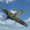
@jhutchi The gen for L1007 found here http://www.airhistory.org.uk/spitfire/p002.html is; L1007 Ia 233 EA MIII FF 15-6-39 AMDP 14-6-39 2x20mm cannon install VA AAEE 21-6-39 hand and perf trls 603Sq 'XT-K' AFDU 10-39 65Sq 5-11-39 609Sq 18-4-40 as proto MkIB 72Sq Drem shot down Heinkel over Scotland 1-40 ? Landed on top of L1085 Drem CE 15-5-40 SOC 28-5-40 She probably wouldn't look too far different to this one found here https://aircrewremembered.com/archibald-william-james.html which I think is X4277 and looks to be in the colour scheme you have in mind.
-
@jhutchi Thanks old fruit.I don't recall where I found this photo but it might be of use if you haven't seen it before I look forward to seeing your works.
-
I had a crack at a cannon armed Mk I a little while ago https://www.britmodeller.com/forums/index.php?/topic/235104119-airfix-cannon-armed-spitfire-mk1-in-148th-scale/ . If you go for the external armoured glass windscreen,flat sided sliding canopy,non kidney shaped underwing cannon blisters,cover over the outer 0.303 ports in the wing leading edge and the associated case and link exit ports and move the cannon shell case exit port inboard to the other side of the adjacent wing rib you shouldn't go far wrong. There weren't many of the first cannon armed Mk I's and they didn't last long in service (about a month I think) 'cos they didn't work very well and the drivers,airframe were landed in a pickle. The few initial airframes that weren't shot down or otherwise written off were withdrawn and made into Va's or Vb's and a couple of them survived into mid 1945. Edit;fabric covered ailerons.
-
Less Than A Tenner Gallery
Alex Gordon replied to Enzo the Magnificent's topic in Less Than A Tenner GB
Hello again Chums,for your delectation may I present my go at the Hobbyboss 1/72nd scale Vought Corsair Easykit. The build thread is here https://www.britmodeller.com/forums/index.php?/topic/235167955-hobbyboss-f4u-1-corsair-in-172nd-scalefinished/ . My thanks to Stix,Mark and Enzo for doing their respective bits and to all who looked in and encouraged.- 37 replies
-
- 24
-

-

-
Hobbyboss F4U-1 Corsair in 1/72nd Scale.Finished.
Alex Gordon replied to Alex Gordon's topic in Less Than A Tenner GB
G'day again Chums,the vinegar stroke this time around. Adrian,Stix,thank you gentlemen. The Airfix decals from way back when came apart on contact with water so I used the Hobbyboss ones which,as I'm finding usual,performed perfectly. I mentioned something about these kits being a decent base for adding stuff.The wing intakes have had a drop of thinned matt black paint,the engine has had some pushrod tubes and an attempt at the ignition harness made from painted copper wire.My bit isn't quite right but it looks the part from a distance. The propellor has had its decals and the fescalised bits of the undercarriage have had a drop of chrome paint. One thing I didn't mention is that I chopped off the pitot probe at the start of this caper and lost it so I've had to knock up a replacement from the ever ubiquitous copper wire. All of this has been cobbled together and I'm going to call this one done. Together with the Mosquito that I prepared earlier My thanks are due to Stix,Mark and Enzo for doing their respective bits and to all who looked in and encouraged.- 15 replies
-
- 12
-
-
-


