Search the Community
Showing results for tags 'airfix'.
-
New super kit announced by Airfix, now up on their site. Available for pre-order.
-
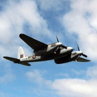
Here I go again, over-committing to a GB 🙄 But who can resist a Mosquito? This is one of my all time favourite kits and I've built a few of them over the years. I got my first one from a model shop in Ayr during the Summer holidays in 1973 and built it as the MkII. This one will be a Banff-based MkVI using the Xtradecal sheet. Placeholder for now, but we'll be back shortly. John
- 23 replies
-
- 14
-

-
 Here we go again, my friends. First some history. On the night of 2nd May 1945 Bomber Command performed their last raid of the Second World War, against Kiel and the surrounding area. Included in the operation were twelve Mosquito B.XVI aircraft of 608 Squadron and it is generally accepted that the last aircraft to bomb was PF505, 6T-D, flown by the CO of 608, W/Cdr Gray, with Capt Mehre as navigator and bomb-aimer. But the aircraft that interests me more is Mosquito RV347, 6T-A, flown by F/Lt Hobbs with P/O Dennis. Facing no lesser dangers than any other crew that night they carried their 4000lb bomb all the way to Kiel, only to have the release mechanism hang up. Apparently unknowingly, they then flew all the way home and landed safely with the fully armed weapon still on board. No mean feat and, in my mind at least, that means they had The Last Cookie Left in the Jar. So, in honour of all unsung heroes everywhere, let us begin.
- 300 replies
-
- 19
-
-

-
- Airfix
- Mosquito .
- (and 1 more)
-
 Expected in Spring (May ?) 2024 - ref. A09010 - Consolidated B-24H Liberator https://uk.airfix.com/products/consolidated-b-24h-liberator-a09010 V.P.
- 351 replies
-
- 46
-
-

-
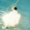
I wasn't quite sure where to put this, but I figured it was part of the RAAF and it does fly... I'd always wanted one of these as I've stood at the very base of the Bloodhound at RAAF Base Point Cook many times and it still impresses me, so when I spotted it at the local toy store I pulled the trigger, thinking hey it would be an easy weekend build. Hahaha no, it took a lot of Mr Surfacer 500 and elbow grease on both the launcher and the missile itself to get it decent. I had an old trophy base laying around and knocked up a little something for it to sit on. I left the missile pretty clean, pictures in service show them nice and white and besides I think they look mean being nice and clean. Decals came from the spares box, they are perhaps a little big but I do have a picture of a missile with larger roundels. Overall I'm pretty happy with how this turned out and really think Airfix should invest in a new mold one as this is very long in the tooth and the molds are showing it, I'm sure it would be a big seller.
- 12 replies
-
- 67
-
-
-

-
-
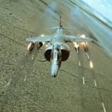
 I'll just leave this here for now 😁 Andrew
 -
A 1/72 Hawker Typhoon is a serious omission from my collection. This has been languishing in the stash since it came out in 2013. The plastic looks OK, I recall reading about this kit and it's slightly unusual design with the wheel bays forming the lower parts of the cockpit and being an important structural part of the wings. I think its a good design but it means some thinking about the painting before joining parts together. (Yes, I know, nasty mold ejection marks). As usual, we start with the cockpit. Additions here are the Yahu instrument panel, the Special Hobby 3D print seat and gun sight (yet to be added). There are lots of posts about Typhoon cockpit colours, but very few colour photos of the real thing, or actual cockpits to look in. There are some good threads featuring a cockpit section at Duxford on the LSP site. I've painted the cockpit and seat as described by Chris Thomas and others in the BM threads. Airfix would have you paint everything with Humbrol 78 - interior green. Pah. The Yahu i/p is pretty good. This example looks a bit tatty, especially enlarged this much, as I've been messing about with it too much. What you see here is a mix of Yahu (the i/p and compass) and Airfix (the side panels and compass holder). I replaced the tube the compass attaches to. Looks better in situ. And let's face it, it's never going to be seen again anyway (but I enjoyed it). Next steps; get the fuselage closed and the wings on. Will they fit? Until next time, Charlie
-
McDonnell Douglas Phantom FG.1/FGR.2 (A06019A) 1:72 Airfix The Phantom bears a familial resemblance to the F3H Demon due to the company of origin for the type, which was intended to be akin to a ‘Super Demon’ with a modular nose for different mission profiles, but in typical military procurement style the world over, the specification was changed completely at the last minute, and resulted in a two-engined beast that could carry a substantial war load, a large, effective radar in the bulbous nose, and the workload spread between two crew members to prevent the confusion of an overwhelmed pilot in the heat of battle. The type was adopted by the US Navy as the F-4A, and as the F-4C by the Air Force, with a confusing (to me) allocation of letters throughout its career, with more confusion (again for me) when it came to the British airframes, and don’t even mention the engines and other equipment. Following a period of project cancellations, mergers and the resulting upheaval in the UK aircraft industry, the Royal Navy & Royal Air Force found themselves lacking capability in the 1960s, with a potential design that could fill is quickly enough. The decision was taken to purchase the McDonnell Douglas F-4 Phantom that was already in use by the US. Two variants were designed to meet the needs of the British, creating the F-4K (FG.1) developed for the Navy and the F-4M (FGR.2) for the Air Force. These aircraft were decidedly different from the US variants however, as it was agreed that larger and more powerful Rolls Royce Spey engines would be fitted, and the radars would be built under license by Ferranti, in an effort to create work for the struggling British aviation industry and wider economy. While the F-4J was the basis for the UK models, the aft fuselage was redesigned by BAC (BAe) to accommodate the larger engines. These changes would mean that the unit costs would more than treble over the F-4J, resulting in the most expensive and dirtiest Phantoms in the world – the Speys were prolific smokers. Due to changes within the Navy, 20 aircraft originally allocated for their use were transferred to the RAF, then in 1978 following the retirement of HMS Ark Royal, all of the remaining Naval Phantoms were turned over to the RAF. In 1999 the powers that be decided to retire the Phantom from service a decade early, the drawdown starting just two years later, the last aircraft retiring near the end of 1992 after 25 years of service that included the purchase of a number of straight-forward F-4Js to replace attrition. The Kit This kit was originally released in 2017 as a brand-new Phantom FG.1, and by the addition of new parts, it is now possible to build either the FG.1 or the FGR.2 from the same base sprues, this boxing offering both choices, plus a new set of decals to complete the job. The kit arrives in a top-opening box that has a dramatic piece of box art, and inside are seven sprues in dark grey styrene, plus a separately bagged clear parts sprue, a large decal sheet and the instructions folded around it. The instructions are printed in colour, but the painting and decaling instructions are found on three folded glossy A3 sheets in full colour, one side for each decal option, and one full sheet for the numerous stencils that seem to cover every Phantom. Detail is good throughout as we’ve come to expect from Airfix, with fine engraved panel lines, plus raised and recessed features in all the right places to assist in creating a realistic replica in this scale. Construction begins with choosing whether you’d like to build an in-flight model, one that is ready to be catapulted from the deck of a carrier, a parked aircraft, or an aircraft that is stored in the hangars with wings and radome folded to save space, although you also have the option of displaying the radar as if it is exposed ready for maintenance in the last option. These options except the parked airframe are shown with a small silhouette in the top right, with a total of five including the visible radar and parked options, so take careful note and keep it in mind during the rest of the build. Now we’re ready to liberate parts from the sprues, and as you were probably expecting, it begins with the cockpit, starting with the two ejection seats. These are built up from the seat chassis with separate cushions that have moulded-in belts, plus a separate headbox with moulded-in pull-handles. The inter-cockpit bulkhead is made from two parts plus a pair of decals, and this is inserted into the cockpit tub, which has three instrument decals for the side consoles, plus another for the electronics panel on the starboard side of the rear cockpit. The finished seats are inserted between the consoles, adding a control column in front of the pilot, then installing a coaming in front, which has moulded-in rudder pedals plus four dial decals to detail the segments of the panel. A bulkhead installs on the front of the cockpit tub, then a little surgery may or may not be needed to prepare the fuselage halves, cutting off a length of sprue that supports the space for the intakes, and optionally cutting away the radome for the two folded-up options. Two inserts are fitted into the rear of the fuselage under the fin, which provide sockets at different angles to change the orientation of the elevators later. In the run up to closing the fuselage, the intakes are made up from two halves, the inner half having the splitter plates moulded-in, which mount on either side of the rear cockpit on three pins. The cockpit tub is then inserted into the port fuselage half, and the two halves are closed, adding a spine insert behind the cockpit, leaving the lower rear of the fuselage open at this stage. A pair of intake fans are moulded in a figure-8 and are inserted by peg and slot to the rear of the two intakes, adding a pair of linked exhaust trunks with no seams to deal with further back at the rear of the engine nacelles. The lower fuselage insert has a portion of the lower wing incorporated, and two inserts depict two auxiliary intakes under the belly, which are closed during flight, but are opened for take-off and when parked. An insert includes the covers for these openings and a large portion of the main gear bay walls, pinning into position on the inside surface. You will need to open-up some flashed-over holes in a large boomerang-shaped insert in the lower wing, which is glued into position, then the completed assembly is attached under the fuselage in preparation for the next steps. First however, two inserts are fitted at the intersection between the lower wing and the engine trunks, adding a decal to the inner face of the intake trunk, then covering it by adding the outer trunk surface, a task that is repeated in mirror image on the other trunk. The upper wing inner panel for the in-flight or un-folded option is laid over the lower wing, and the tail fin is plugged into the top of the fuselage by a large hollow tab, gluing the rudder into position at the rear, then adding the stabilisers into their slots at the angle set by the inserts fitted earlier. As most aviation fans know, the Phantom’s outer wing panels have a pronounced dihedral, which is achieved by the tabs moulded into the outer panels, which locate on two circular pegs moulded into the inner wing. The two flying surfaces (flaps/ailerons) fill the gap between the wingtip and the root, adding deactivated slats on slots to the leading edges. You have a choice of deploying the airbrakes under the wing, or cutting off the angled supports to mount them flush with the skin of the wing, repeating all this on the other wing. To fold the wings, different outer wing panels are included, mounting on the wing in the same manner as before, with a different angle moulded-in, adding the flying surfaces and slats, but without the option of open airbrakes. Another pair of optional vents near the ends of the exhaust trunks are included, which are closed for flight and opened for launch/take-off or storage, then a pair of chin intake lips are installed under the nose, a pair of small inserts under the exhaust trunking, then the bulky exhaust petals are fitted to the ends of the trunking to complete the engines. The in-flight option has separate bay door inserts that simplify the process by using one part in each bay that has engraved panel lines moulded-in to depict the individual parts, and completes the task with just three parts that sit flush without any juggling. For wheels down, the main gear legs are single chunky parts that have a retraction jack added, with two captive bay doors attached on tabs, and the inner doors locate in the edges of the bays, hanging downwards. Each wheel is a single part that slides over the axle at the end of the single-sided yoke. For catapult launch, the nose gear leg was extended to give a higher angle-of-attack and lift to the wings, and this is built from two parts with an overlapping joint for strength that is reinforced by a peg and slot within. To model the leg in normal take-off or ground-handling mode, the extended scissor-link is cut away, and mated to a shorter lower section, both options plugging into the same hole in the bay roof, using the same retraction jack and twin wheels, as well as the bay doors at the front and starboard side of the bay. We have a break now for weapons and fuel tanks, fitting either a four-pack of Skyflash missiles, or four practice rounds, all fitting into semi-conformal troughs in the underside. There is also a choice of a small two-part fuel tank or a larger tank with an additional pair of fins at the rear, either one fitting on the centreline station, or without any additional tankage by inserting a strip in the mounting slot. There are also four AIM-9 Sidewinders, four dumb bombs, and four rocket pods, all on dual ejector rails, the Sidewinder rails able to be double-stacked under the bomb or rocket pod rails. A diagram shows which stations they can be mounted on under the aircraft, and the pylons are shown overleaf. The options keep coming, with a deployed or closed refuelling arm, arrestor hook that can be show lowered for trapping-on, or cleaned up for flight. The last common steps have the coaming and HUD inserted into the front of the cockpit, and if you plan on leaving the canopy closed, there is a single-part canopy option. For an open canopy, the windscreen and hoop between the crew are glued in place, then the two openers are fixed at an angle to allow the crew access. The final page is dedicated to the radome, which for some options you will have cut off at outset of the build. The parts that were cut away can be discarded, as there are new parts with ribbing moulded into their interior. One option has the radome and radar folded open for space-saving below deck, using a figure-8 insert that has the dish and support fitted, covering the dish with the radome, which will be dimly seen through the interstices, the other side of the figure-8 plugging into the opening at the front of the fuselage. To portray the radome folded to access the radar equipment, the radar mechanism is built from two well-detailed halves, onto which the dish is slipped in preparation. The radome is glued to another figure-8 that is hollow and has a notch in the top of the other loop of the 8. The assembly is glued to the front of the fuselage, and the radar equipment is inserted into the fuselage, using the notch for orientation, and checking the transparent diagram for additional location information. Markings There are three decal options in this boxing, and each one has a side of A3 devoted to the profiles, with the stencils handled by a separate double-sided page of line drawings to keep things as simple as they can be. There are a LOT of stencils, but you probably knew that going in, and fair play to Airfix for including them all. From the box you can build one of the following: Phantom FGR.2, No.56 Sqn., RAF Wattisham, Suffolk, East Anglia, England, 1991 Phantom FG.1, No.43 (Fighter) Sqn. ‘Fighting Cocks’, Air-Speed record between Land’s End, Cornwall, England to John O’Groats in Northern Scotland, February 24th 1988, flown by Wing Commander John Brady & Flight Lieutenant Michael Pugh-Davis Phantom FG.1, No.892 Naval Air Squadron, HMS Ark Royal/USS Saratoga, 1978 – this aircraft was ‘zapped’ during cross-carrier operation, adding a star to the fuselage roundels and adding ‘Colonial’ in front of Navy Decals are by Cartograf, which is a guarantee of good registration, sharpness and colour density, with a thin gloss carrier film cut close to the printed areas. Note that the printed instructions from Airfix state that Option A was flown by 53 Sqn., but as you will see from some of the posts below this review, that wasn't the case, and it was in fact 56 Sqn. It's very easy to hit the wrong key, so we'll let them off Conclusion The number of options you can choose gives a lot of choices to individualise your model, whilst the detail is right up to modern standards given the limitations of scale. Three interesting decal options should appeal to many, and being able to build both an FG.1 or FGR.2 from the same box is a good thing. Highly recommended. Review sample courtesy of
-
Supermarine Spitfire TR.9 (A05143) Two-Seat Trainer 1:48 Airfix The Supermarine Spitfire was the mainstay of British Fighter Command for the majority of WWII, in conjunction with the Hurricane during the Battle of Britain, with the Mk.IX being the most popular (with many) throughout the war, seeing extended periods of production with only minor alterations for the role for which it was intended differentiating between the sub-variants. Originally requested to counter the superiority of the then-new Fw.190, a two-stage supercharged Merlin designated type 61 provided performance in spades, and the fitting of twin wing-mounted cannons with accommodating blisters gave it enough punch to take down its diminutive Butcher-Bird prey. The suffix following the mark number relates to the wings fitted to the aircraft, as they could vary. The C wing was also known as the Universal Wing, and saw extensive use because it mounted two 20mm cannon in each wing, the outer barrel usually covered by a rubber plug. The main gear was adjusted in an effort to give it more stable landing characteristics, and bowed gear bays removed the need for blisters on the upper wing surface, helping aerodynamics. The Mk.IX is considered by many to be the definitive variant of the Merlin-engined Spitfire, and over 5,600 of this type were made during WWII, the majority built at Castle Bromwich. Although there were two known two-seat two-seat Spitfire conversions during the war, one of a Mk.V by a British squadron, and one Mk.IX by the Soviets for training their pilots, it wasn’t until after the war that it became official, starting with one Mk.VIII that was built by Vickers as a demonstrator. Ten T.Mk.IX trainers were exported to India for their training needs, with a further six sold to the Irish Air Force for their training and conversion requirements in 1951, converted from redundant Mk.IXs. The Irish airframes were also able to be used for gunnery training thanks to the retention of two .303 machine guns in the outer wing stations, one in each side, that allowed novice pilots to engage in target practice with the security of knowing that they had a tutor in the back seat in case of issues. Of those six, four survived retirement and went into service in the warbird community, taking paying passengers on pleasure rides that are still ongoing at time of writing, despite a recent forced belly landing by one of the small fleet that was light enough for the pilot and passenger to walk away almost unscathed. Hopefully that airframe will be back in the skies once repaired and its engine has been rebuilt after the shock-load imparted by the prop when it impacted the ground. The Kit This is the first boxing of a new tooling from Airfix, one of the first to have the exterior fully riveted, which is bound to split opinion, as usual. Speaking personally, I like them, as they add extra visual interest in areas that might otherwise look bland, and although we all know that rivets aren’t generally holes in the skin, we also know that windscreens aren’t 6” thick, and that modelling is always a compromise in some shape or form. Now that’s out of the way, let’s get on with looking at the model. The kit arrives in a top-opening red-themed box, with a painting of an Irish TR.9 in green with their orange/green yin-yang meatball roundel on the wings and fuselage. Inside the box are four large sprues and a smaller one in dark grey styrene, a separately bagged clear sprue, decal sheet, and the instruction booklet that is printed in spot colour on white paper, with full colour profiles of the decal options on the rearmost pages. Detail is excellent, extending to the usual points of interest that include the cockpit, gear bays, plus other exterior features both raised and engraved. The inclusion of a fully riveted and panel lined exterior skin is a new feature for Airfix, and adds to the appeal for many modellers, as above, which coupled with Airfix’s clever engineering of their kits and excellent marketing and distribution network, makes for a better product for us modeller. Construction begins with the dual cockpit, and while the component parts will be very familiar to anyone that has built a Spitfire before, the unusual aspect is the provision of another seat and controls in the rear. Because the front cockpit has been moved forward to accommodate the extra seat, the bulkhead with the pilot’s instrument panel has a shallower profile than the norm, attaching the compass mount in the footwell hole, and adding this and the forward spar to the port sidewall insert. The forward floor has a pair of pegs removed from underneath, fitting rudder pedals, then sliding it into the cockpit from the front via the footwell cut-out, and securing the rear through the spar before adding a cross-bar to the seat frame and putting it into the slot that marks the rear of the first cockpit. A short bulkhead is set behind the front cockpit, making up another floor section with rudders, and sliding that carefully into place, taking care not to bend the narrow areas that project into the front cockpit and through the rear bulkhead. A narrow port side console is made from two parts plus a decal, fixing it to the cockpit side straddling both compartment, locating it on the recesses moulded into the wall. The front seat will be very familiar, consisting of the pan plus two sides, and an adjustment lever on the starboard side, attaching the support frame to the rear, then fixing it in the cockpit after the glue has cured. The starboard cockpit wall has three pegs removed from the rear, and a wiring loom fitted before it is joined to the growing assembly, adding another slim console with throttle quadrant and decal to the starboard side after the two walls are in position. The tutor’s control column is a two-part assembly, fitting a ledge to the starboard footwell before it is closed in with a shaped bulkhead, then sills are fixed to the top of the cockpit assembly, and another two-part control column for the trainee is added. The tutor’s seat is made in the same manner as the front seat, attaching it to another seat frame with rail glued across the top, sliding the completed assembly into the rear of the cockpit assembly, then fitting the front and rear instrument panels after painting and decaling them with dials and other details. The trainee’s sidewalls receive a throttle quadrant and landing gear control assembly, the former on the port side, the latter on the starboard. A support is fixed between the top of the tutor’s panel and the roll-over behind the trainee’s head, then you have the choice of whether to populate the cockpit with pilots or not. Two crew members are included on the smallest sprue, and the pilot in control has separate arms to allow for a more realistic pose than the old hands-on-lap chaps of yesteryear. Both pilots are inserted into the cockpit at this stage, adding the arms to the pilot once they are in position, but if you don’t feel the need, you can leave one or both in the box. Before the fuselage can be closed around the cockpit, you should make the decision whether to pose the canopies open or closed, as the sills need to be removed for the closed option. Fortunately, Airfix have included two jigs for the sides that allow you to cut the forward sills off without issue, providing you don’t forget yourself and glue the jigs in place in a moment of madness. To pose the canopies open, the access doors are cut out along the thinned edges, as shown on the instructions, with replacement parts provided on the sprue, noting that the aft door is much shallower than the pilot’s, and as it is post-WWII, you can paint the diagonal crowbar bright red without risking pillory from the purists. Another piece of equipment is added to the moulded-in ribbing in the top of the fuselage on the starboard side, a filler cap is inserted in front of the windscreen, and a platform is installed in the belly aft of the wings, ready to receive the two relocated oxygen bottles that usually stand upright behind the pilot seat. The completed cockpit can then be trapped between the two fuselage halves, which is where we can see a new engineering decision that will lead to a better joint on the cowling over the Merlin engine. Instead of moulding half the cowling into each fuselage half, it has been created as a separate part that is given the correct shape and form by using sliding moulds, which results in fine seamlines that need little clean-up, and shouldn’t reappear like many Spitfire cowling seams have in the past, which I’m sure many of us can attest. Each elevator panel is made from upper and lower skins, slotting into the tail on either side, adding a full-span flying surface across the concave trailing edge, and trapping it in position with an insert in the centre. This allows the modeller to deflect it as they wish, adding the rudder behind, which can also be deflected for a more candid look to the finished model. The lower wings are full-span out to the tip-joints, and have a pair of radiator housings inserted after fixing the cores front and rear inside them, and gluing the cooling flap to the rear, which can be set open or closed. Flipping the lower wing over, a pair of circular bay walls are added to the cut-outs, linking them with a pair of parts that perform the dual task of bay sides and also act as spars to keep the dihedral of the wings from sagging. A circular light is embedded in the lower wing toward the trailing edge, then it can be mated to the fuselage, gluing the upper wings over the top, and installing the ailerons in their cut-outs near the tips. You have the option for wheels-up or down with this kit, the easiest option being in-flight, requiring the installation of the fixed tail-wheel under the rudder, and a custom set of main bay doors that have spacers moulded-in, which prevent the parts from dropping into the bays, and give enough space for the simplified wheels to attach to the integrated axles. To model the TR.9 on the ground, a pair of struts are made with separate scissor-links and captive bay doors, both inserting into the bays and locating securely in position with the help of some sensible engineering. The wheels are moulded as tyres that have block tread (typical of post-war use) moulded-in along with the rear hub, adding the front hub before installing them on the stub axles at the lower end of the leg. While the model is inverted, an L-shaped pitot probe it glued under the port wing, and a pair of small hooks are installed between the radiator housings. Attention moves back to the fuselage, concentrating on the nose and cockpit to finish off. The six-stack fishtail exhausts are moulded on the same sprue as a set of tubular stacks, so ensure you fit the correct option before proceeding. Each set comprises two parts that hold three stacks each for extra detail, hiding the mating surfaces inside the cowling after they have been inserted into the slots in the sides of the nose. The four-bladed prop is moulded as a single part that is bracketed by the spinner and back-plate, which is placed against another plate that is skewered by a stepped pin that should allow the blades to spin if you are careful with the glue. The assembly is then glued into a cup that slides into an oversized hole in the front of the nose, again being careful with the glue to keep the blades moving. As mentioned earlier, the canopies can be posed open or closed, and by now the decision should have been made. To have the canopies open, the windscreen, aft section of the forward cockpit and the windscreen/spoiler for the aft cockpit are glued in place, fitting the two openers in the retracted position as shown on the diagrams, fixing the open doors in the down position on the port side of the fuselage that should have been cut out earlier. If closing the cockpit, a small section of the front cockpit sill should have been removed using the jigs supplied, allowing the combined opener and fixed aft section to be glued in place over the cut-out. The same aft opener is used for both options in this kit. Markings There are two decal options in this kit, one in service with the Irish Air Corps, the other in civil service as a warbird. From the box you can build one of the following: Spitfire TR.9, B Flight, Irish Air Corps/An tAerchór, Baldonnel Aerodrome, Dublin, Republic of Ireland/Poblacht na hÉireann, 1951 Spitfire TR.9, Iver, Buckinghamshire, England, 1969 Decals are by Cartograf, which is a guarantee of good registration, sharpness and colour density, with a thin gloss carrier film cut close to the printed areas. For the Irish option, the widths of the orange/white/green stripes under the wings are shown for those that prefer to paint larger markings to avoid carrier-film steps, and separate Trestle-Here markings are thoughtfully included on the decal sheet. Conclusion While the TR.9 Spitfire played no part in the Battle of Britain or the rest of the war, it was an interesting bit-part player post war, and is a familiar sight in the skies around Britain and at airshows. It’s also about the only way any of us will ever get to fly in a Spitfire without using a time machine. Airfix have done a great job of tooling this kit using modern techniques, and the upgrade of detail levels really shows. Very highly recommended. Review sample courtesy of
-
 Hi All, My latest completion is Airfix' lovely Wellington, completed as a Mk.Ic R1378 of 311 (Czechoslovak) Sqn, based at RAF East Wretham in 1941. Here's a photo of the aircraft (the middle of the 3): As you can see the scheme is quite unusual, with the wavy camouflage demarcation, the blacked out roundel and the lack of beam windows. The build was pretty much OOB, albeit with an Eduard mask set. The markings were cut using a Silhouette Portrait 3. Here's the WIP if anyone is interested: Anyway, on with the photos! Here's a couple of shots with another twin-engined Bomber Command stalwart from the early war years: And with a couple of accessories from the Bomber Command resupply set: This has been a thoroughly enjoyable, straightforward build and I am pleased with the outcome. Thanks to all who have added kind words along the way - it has been much appreciated! Thanks for looking, Roger
- 25 replies
-
- 66
-
-
-
-

-
 Hi all - it's been about 9 months or so since I last spent some time at the bench, due to a number of factors including moving house, job, and life stuff in general taking up most of my time... so I have decided to try and get some mojo back with a relatively simple build. I know very little about jets, but the Airfix 1/72 MiG-17F looked like a pretty straight forward build, plus I have always liked the looks of this stubby little fighter. I plan on doing this one completely out of the box with no modifications, to avoid getting too bogged down in the details. I had heard of some fit issues with this kit, especially up front around the nose panels, so dry fitting up front was going to be a must to see what could be done to ease any fit issues. The main culprit is the cockpit tub pushing the front of the fuselage out a bit so that the under-nose piece doesn't fit, but with some sanding around its edges, the fit issues look largely manageable. I will still have to add spacers to the nose ring piece as it is too narrow and doesn't fit as well. With the fit tested, I decided to get the cockpit done. It is simple but detailed enough, even if the instrument panel is a flat piece with a decal. Next, the instructions show you to add 20g of weight to the nose forward of the cockpit. I am no physicist but without a very heavy material there's no way 20g fits in there... so I have loaded up the forward fuselage around the cockpit with weight... I hope it will be enough....! Next, the exhaust pipe and I should then be in a position to close up the fuselage and wings. Hopefully that will go smoothly. Thanks for looking! Brad C
 -
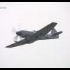
Before XM607 became famous by bombing the runway at Port Stanley on the Black Buck missions she was flown to the US on the Red Flag 77, were she had a middle stone/dark earth underside paint scheme. Unfortunately this was unsuccessful as the pilots reported they couldn't really hide the Vulcan massive shadow when flying over the Arizona dessert at 500 feet above ground level so they were authorized to fly as low as 300 feet agl. Due to waiting for a new nozzle for my airbrush (coming from Germany) and after speaking with Tom Probert at the last club meet I decide I would finally start the Vulcan that been sat in the stash for nearly 2 and 1/2 years, I'd already goth old of the Kits World decals which has the right sqn and serial number marking (I think you can model any B2 variant) to do the Red Flag 77 scheme when I received the kit. Must say I'm impressed how quickly such a large amount of plastic can go together My intent is to position the nose up 20-30 degrees as if on climb after take off so I built a plastic block and drilled through a 10mm hole for the acrylic rod and then used another block to prevent the rod from rotating. Its a bit rough but I made it oversize so I can file to fit inside the bomb bay. Next thing to do is find a lump of real wood for the base, don't want MDF this time.
-
Expected in Spring (May ?) 2024 - ref. A06023 - Boeing Chinook HC.1 Source: https://uk.airfix.com/products/boeing-chinook-hc1-a06023 V.P.
- 156 replies
-
- 24
-
-
-
New airfix kit in progres is a 1/72nd Fokker E.II/E.III Eindecker Source: http://www.airfix.com/uk-en/news/workbench/workbench-behind-the-scenes-at-airfix/ V.P.
-
 I originally had the idea of doing a Whatif Lightning FGR.7 with ALL the weapons mounted to it with some trumped up idea of Jaguar and MRCA being delayed or cancelled or whatever other politically expedient excuse would pass muster. Then I decided I had enough on the go without spending ages umming and ahhing over whether something should be an FGx, or an FRSx, or a BRx etc etc. So, because I want to model a Lightning in Beast Mode, I've decided to do an F.53 diorama based on the numerous photos from 1967-1969 of the BAC display at various Airshows (exhibit A & B below courtesy of the internet). I'll be starting with the Airfix Lightning F.6 kit (for obvious reasons), and generally 3d printing the various bits that can't be bought or found for love nor money. As I've only recently bought a 3d printer this promises to be a doddle painful learning experience that I'm sure I'll regret ever embarking upon. So, onto the obligatory box shot... Fabulous artwork, note the inspired use of colour palette and copious amounts of alcohol leading to forgetting to finish the image.... (or whatever the excuse was)... For the F.53 specific weaponry I managed to obtain the Odds & Ordnance underwing stores kit from rossm on here. The CBLS is available though Air-Graphics, but the rest I can't find anywhere, so the list of bits to 3d print (as seen in photos above) is as follows: - JL100 double stack with overwing pylons - Matra 155 double mount (OAO kit is single mount only) - Matra 155 open cones (i.e. without frangible cover. These will be to modify the resin ones I already have which are too fiddly to paint!) - Ventral rocket pack (how has this never been available?) - 540lb bombs - Drop tanks (from a Strikemaster but I'm not buying a whole kit just for 2 of these) - RAE Universal Twin 7.62mm Gun Pod - Firestreak ventral pack - Red Top ventral pack - Reconnaissance ventral pack - 1000lb retarded bomb with semi-deployed parachute (still scratching my head over how to do justice with this one) - Aden cannons in a naked state - A multitude of 2" and 3" rockets..... painting 188 of these promises to be (insert expletive here) delightful The vast majority of the above don't have easily accessible drawings (and I'm not willing to join a billion sites and get spammed for the rest of my life just for some blueprints), so I'll mostly be working from a handful of reference books, photos and whatever Google shows me. I intend for things to be detailed enough that an armourer would recognise what they are supposed to be, but I'm not going to model every rivet and safety catch, mainly because my printer won't do that level of detail, but also because I want to finish this before the apocalypse. As far as the airframe goes, unless someone can direct me to some 1/72 Queen's Award roundels I'll likely be doing the G-AXEE Kuwaiti scheme from the Paris Airshow rather than the G-AWON scheme seen in most other photos from the period. Either that or I need to get creative with Microsoft Paint and some waterslide paper. I've already made some reasonable headway with design & print loops to refine some of the parts, but its late, I've been gardening ALL weekend and I really need a shower, so a progress-so-far-post will have to wait until tomorrow. Stuart
 -
This will be my contribution to this particular party. Yes it’ll be another Airfix Mosquito, along with a selection of after-market bits to slow me down even further. The Xtradecal sheet has one particularly intriguing option, shown below. It’s KC-L allocated to 617 squadron - a Dambusters Mosquito. This looks to be unusual as although 617 squadron used a number of Mosquitos in the pathfinder role in the latter stages of WW2, I gather that these were loaned from other squadrons and usually didn’t spend long enough with 617 to get their codes repainted. I’m guessing that 617 would have been using the borrowed Mosquitos very much in the ‘master bomber’ role, which I need to read up more about during the build. For inspiration I have these ‘Mosquito Pathfinder’ I am finding virtually un-putdownable, a first hand account of flying pathfinder missions. A definately recommended read. For now I’ll shuffle nervously towards the start line and wait for the starting gun.
- 83 replies
-
- 17
-
-
When Airfix released their "new" kit back in 2021 I put it on my list of things to buy when I had the cash available and this GB has finally given me an excuse I guess.😄 I have previously built 9 Mossies, starting with the original Airfix release way back in 1957, which I remember well as it had a part missing so I sent off the complaint slip and promptly received a complete replacement kit - no messing about with just sending the missing part in those days! That was followed by the Frog B.IV about 10 years later, and then 3 of the second Airfix multi-version release from 1972 onwards. After that came the Matchbox B.IX/NF 30 which I built as the night fighter version but attempted a "conversion" on a second old moulding Airfix one using the spare bomber parts. More recently I built the Tamiya B.IV to replace the inaccurate Frog one, and also the 2005 reboxing of the Airfix second moulding as an NFXIX. Over the years I have scrapped 3 models but I still have the NFII, B.IV,FBVI, FBXVIII, NFXIX and NF30 though the latter has been stripped ready for a complete refurbishment which I will do in parallel with this new build, though it won't be eligible for the GB as it is over the 25% limit. I was tempted to build a recce version for a change but then saw the bomber at a reasonable price so here it is. I won't bother with sprue shots as they are pretty well known by now. I was intending to build OOB but it seems the initial reports of how accurate the kit was were not entirely correct. Together with a few inaccuracies in the undercarriage assembly, the main problem seems to be with the bomb bay doors where Airfix have I gather inadvertently scanned those of a target towing plane pretending to represent a bomber, due perhaps to a lack of research. As the Freightdog replacement doors are not currently available I will have to modify the kit ones it seems. At least I will have the example of several other modellers builds to study as I go! Pete
-
 Hello All Here is my take on the well known Airfix Folland Gnat T.1 in the Yellowjacks Aerobatics Team colours, c1964. Overall, it's a lovely little kit except for the panel lines which, like a lot of the newer 1/72 Airfix kits, are far too wide and deep. I decided to try a new method (to me)and filled them with 3D, UV cured resin, then, instead of re-scribing, I drew them on with a 0.3mm pencil after painting. The access panels (of which there are many !), were created as svgs and printed onto clear decal paper. The only add ons used were Wolfpack Resin seats and SBS resin wheels, although to be honest, the kit's wheels aren't too bad and could have been used. I decided not to use gloss yellow as I felt that I wouldn't get a realistic finish. Instead I opted for a matt yellow finish, then built up the gloss gradually with multiple coats of Johnson's Pledge. Being all yellow, I thought that the end result may end up looking a bit bland and toyish in the small scale, so to give it a bit of character, and after looking at some online photos, I decided to spray the upper wings and rear fuselage a slightly different shade of yellow. Paints used were predominately Vallejo Model Air with some Tamiya and Mig Ammo. Decals were OOB. The more observant will notice a lack of rear seat windshield. This is not a kit part and something that I did try to scratch-build. However, the actual item is made up of multiple compound curves and I just couldn't get it to sit properly, so gave up ! Thanks for reading and taking the time to look. Comments and critiques will be most welcome. Gary
- 19 replies
-
- 71
-
-
-
 The workbench has recently looked like a hand grenade was dropped on it, 3 builds on the go with similar parts, the perfect recipe for a cock-up! Really enjoyed doing them though, Airfix really hit the mark with my aviation interests, although the Blenheim's fought a little at times. There is some speculation over colours on the Beaufort and Blenheim Mk.I, and I've mixed some of my own shades on the light Mediterranean blue and light earth, but not too bothered as long as they look about right. All paintwork is MRP lacquers. The builds are here: With 3 builds, I've not included all the pics, but there are a few more in the link below: Bristol Builds I haven't fitted the ASV aerials yet, but need to either get some or make some. Thanks for looking
- 22 replies
-
- 72
-
-
-
-
-
Well, I've been dithering about WHAT Mosquito I'd like to settle on as a subject- and also which kit. In the process of tidying up my "stash of doom", I rediscovered a bagged 48th Mossie, which I thought was a Tamiya B.IV. Well, I just pulled it out, and it turns out to be an Airfix FB.VI. (I wasn't completely wrong- there was a painted-up Tamiya cockpit/interior assembly in the bag, complete with spars that have nowhere to go on the Airfix fuselage.) I'd been thinking a post-war FB.VI might be interesting, but I also had another (even) less conventional idea, which also requires a "fighter nose" airframe. I've got a bit more investigation to do, so I'll leave you all hanging on the edge of your seats for the moment. (cough DD723?) (As I commented in the chat thread, I was also trying to talk myself into a 72nd Airfix PR.XVI, but now that I've caught up with the state of play in this build group, I see there are more than enough of that kit represented, so I'm just as happy to stick with this one.) bob p.s. I'm off to a meet today, as a voyeur and with a few kits to put on the club sales table. Even with a too-large stash, however, I won't rule out an "opportunity buy". For some reason I think I'll be especially aware of Mosquitos while I'm browsing...
-
 On 16th June 1945, Squadron Leader Clifford Grainger Andrews DFC with 684 Sqn. made the first of two flights over Mt. Everest to help survey a second route to the summit. There’s an excellent article on the website of the New Zealand Airforce Museum. From his logbook, it’s evident that he flew a Mosquito XVI coded ‘O’ for the mission- although the serial is too small to read in photos. The June ORBs aren’t in the archive, but thankfully the May records are, and Mosquito ‘O’ appears as NS704. NS704 is a PR.XVI from the same contract and delivery dates (Between 24-3-1944 and 31-12-1944) as NS787, the aircraft illustrated in the photo below. Source: IWM Source: IWM This means an overall High Speed Silver finish, with SEAC roundels and ID bands in the same dark blue. The PRU Blue slipper tanks are noteworthy too. I plan to cut masks for all markings, although may use some of the kit stencils where necessary. As always, a little inventory to start with.
- 48 replies
-
- 10
-
-
-
Airfix is to release in Spring 2025 a 1/48th Supermarine Spitfire Tr.9 kit - ref. A05143 Sources: https://uk.airfix.com/products/supermarine-spitfire-tr9-a05143 https://www.facebook.com/officialairfix/posts/pfbid025p67UbcHsaGw31NDoe757dbq3zNoCCjaBeD3xiQDTzuaV8uEVZgyzCLcr7R7SJg5l Introducing the NEW MOULD 1:48 scale Supermarine Spitfire Tr.9! Arguably the most famous fighting aeroplane in history, with over 20,000 aircraft eventually produced, the Spitfire Tr.9 is a two-seater trainer aircraft. This highly detailed kit includes: • 128 parts • Two scheme options • Unique subject not previously available in injection moulded kit form • Fine rivet detail and slide moulded engine cowling • Specific post-war wing parts • Both canopies can be posed closed or open to reveal the detail in both cockpits • Decal options for an Irish Air Corps Spitfire Tr.9 and a famous post-war camouflage scheme Test build Schemes V.P.
-
I did promise @Johnson to do another Mosquito and I did promise to treat myself to a new tool kit this time - so I'm in with the Airfix B.XVI. I chose this kit as it has the fuel tanks provided, which you can see from the bomb bay (the newer PR.XVI kit does not!) I like bombers in black so I'm going to do the 109 Squadron option. I'm looking forward to this and everyone else's builds.
-
Hello, Here's my next project, a dual build which will carry me through most of the year. I'm continuing the trend of building my oldest kits first, in case I can still use the decals 🙂. One of the kits is a newer repop I purchased in 2019 in Airfix's soft light grey plastic. The other was purchased in 2004, and it's the harder dark grey plastic. They will be a Seafire FR.47 and a Seafire F.46 respectively. I've seen build reports outlining fit issues with the FR.47 and I know the soft plastic works well with TET and may make the build easier. I'll also use a bunch of goodies, like the Barracuda propeller blades and the requisite Rob Taurus canopies. I also got miscellaneous bits (flying surfaces, exhausts, wheels, cockpit bits) from Hi-Tech which I'll put to use on one of them, likely the F.46. I'll have to check my "Spitfire Goodies" box as well to see if there is anything else there worth using. Here is the start. The newer decal sheet is much crisper in printing though I'm not sure if there will be a difference in behaviour. And the first challenge has raised its head: the instrument panel. It's molded in three levels, and I doubt any decal sheet would conform to all of them. The panel in the older sheet is also useless. IMG_5089 by Wlad Franco-Valias, on Flickr Unfortunately Airfix moulded all but one instrument face as flat discs, so my usual method of painting white first, then flat black and scratching the instrument details won't work here. I thought of punching out the individual instruments from the decal sheet, yet with only one usable sheet that's not a good plan. I've painted the panels with Tamiya LP-2 White for now while I figure something out. The other challenge is the control column with a solid spade grip. What was Airfix thinking? I'll scratch build the grips as the Mk 47 has a differently shaped grip. IMG_5090 by Wlad Franco-Valias, on Flickr While the kit is good, there are many things to correct and enhance which can make the build interesting. I've just completed a shake and bake kit, now it's time to get creative again. This may be it for a while. Cheers, Wlad PS - I recognize beauty is in the eye of the beholder, so please don't be offended if you prefer the Mk.47 over the Mk.46. 🙂
- 32 replies
-
- 17
-
-
-
Hi All, After a very difficult and stressful few weeks (which has included 3 unscheduled weeks in the UK), I am back on home soil jet-lagged and in need of some plastic relief. I must praise the modelling (and sleep) gods that tomorrow is a public holiday here due to the Monarch's Birthday (although it is not, but who am I to complain?!). Although I have built a couple of boxings of Auntie's Wimpy over the past few years, I feel like I have never quite 'nailed' it. This then is the perfect opportunity to rectify this situation. This time around I shall be building a Mk.Ic from this boxing: From memory, previous boxings were in Airfix' light grey, soft styrene, whereas this newer boxing uses the 'new' harder mid-grey plastic. Here's the sprues: The transfer to the newer plastic certainly does not appear to have done any harm, with the mouldings beautifully crisp. Here's the decals along with the only after-market addition: Although the boxing allows for an attractive early war scheme (a 9 Sqn aircraft based at Honington in December 1939), a bit of research turned up this rather attractive scheme: I have chosen to model R1378, the middle of this trio. 311 (Czechoslovak) Sqn were based at Honington when first formed, but by the time of this photograph in March 1941 they had moved to RAF East Wretham. There is a little information regarding the aircraft on this website: https://fcafa.com/2012/01/19/wellington-aircraft-of-311-sqn/ According to this R1378 crash landed at East Wretham after a starboard engine fire on 18th May 1941 following a raid on Bremen - the aircraft was piloted by Sgt Leo Anderle. Of note with the scheme are the high wavy camouflage demarcation, the non-standard roundel with the white overpainted with black, and the lack of beam gun positions - squadron, aircraft and serial codes are all in MSG. All make for a most pleasing scheme, so I shall look forward to some plastic butchery occurring soon! Thanks for looking, Roger
- 52 replies
-
- 22
-
-