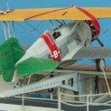
patmaquette Posted January 3, 2023 Share Posted January 3, 2023 Hi everyone. I intended to build this model last year, but never got round to it. This group build gives me the stimulus (kuta) to get it under way! I've had a couple of Revell/Monogram 1/48 Catalinas maturing in the cellar for some years. One is a PBY-5 and another a PBY-5A amphibian. The idea to build a "MAD Cat" came after I visited the very interesting air museum at Dunkeswell airfield, just east of Exeter, where four of these aircraft operated during 1945. The museum chairman, Brian Lane-Smith, sent me further information and my hope after completing this group build will be to give the model to the museum for them to hang from the ceiling to display the weaponry on the underside. "Mad Cats" was a nickname given to USN Patrol Bombing Squadron VPB-63 after they were equipped with Catalina's installed with a Magnetic Anomaly Detector (MAD) and retro-firing rockets for searching out and destroying submerged U-boats. The subject chosen for the model is PBY-5A Bur No 48318 that was flown by Lt F G Lake which sunk U-326 using retro-rockets whilst based at Dunkeswell. <USN photo> The snort spray of the submerged craft was sighted near Brest from an altitude of 2000 feet and Lt Lake flew up the wake and delivered a retro rocket pattern using the MAD contact. This was the last time (April 1945) the retro rockets were used in combat, although of course MAD continues to be used. The idea for MAD came about due to heavy losses in merchant shipping from U-boats along the USA eastern seaboard early in the USA's involvement in the war. The USN were exploring solutions to overcome these losses. Initially greeted as a promising solution, it was only with later experience that it was found limiting when searching open waters. The method looks for localised variations against background magnetic fields caused by the steel hull of the submarine, but the insensitivity was such that it was necessary to fly at low altitudes (at least below 400 ft, typically 50 to 150 ft). A group of four aircraft flying line abreast was used to get a wider sweep, but even so, the likelihood of finding a submarine in open water still remained remote. There was a greater chance of success where the area needing to be searched was smaller. The entrance to the Mediterranean proved to be a successful hunting ground. VPB-63 aircraft based at Gibraltar patrolled along a search path (known as "the fence") crossing the Straits. When first detected, the position of the submarine was marked on the surface by dropping a smoke or light float. Further would be dropped over a number of passes so the course and speed of the submarine could be seen. This was followed by the attack pass. <US Navy photo of MAD boom & float> (Edit: I now think this is not a float, but another type of MAD. See my later posting for details) The MAD contact signal was produced when the aircraft flew over the target submarine, so any ordnance released at this point would overshoot the target owing to the aircraft's forward speed. Caltech were assigned the task of solving this problem. They built upon some earlier work on a shipboard anti-submarine rocket called "Mousetrap", a 7.2" rocket developed from the Hedgehog spigot bomb, to have it launch rearwards to counteract the forward motion of the aircraft. The rocket motor had to be increased in size from 2.25" to 3.25".to produce the thrust to counteract the aircraft speed; indeed three motors were developed to correspond with different aircraft speeds. The explosive in the warhead remained at 60 lb, but was uprated from TNT to Torpex by the time the weapon was put into service. <US Navy photo of Hedgehog bomb> The Catalina was fitted with launch rails beneath the wing, just outboard of the struts. A heat and blast shield was positioned above the rails to protect the wing from the rocket exhaust. There were 12 rockets beneath each wing, later increased to 15. The rockets were launched in three salvoes from an intervalometer to produce a box pattern over the target. <US Navy photo of retrorockets under wing> Thanks for looking, and I'm looking forward to getting this build under way next week, Pat 24 Link to comment Share on other sites More sharing options...
TonyOD Posted January 3, 2023 Share Posted January 3, 2023 This is going to be a great. At 1/48 it'll be a beast! 1 1 Link to comment Share on other sites More sharing options...
Wings unlevel Posted January 4, 2023 Share Posted January 4, 2023 Fascinating subject, yet another SSD GB thread intro post where I’ve learnt something new! How will you replicate the rockets? 1 Link to comment Share on other sites More sharing options...
patmaquette Posted January 4, 2023 Author Share Posted January 4, 2023 9 hours ago, Wings unlevel said: Fascinating subject, yet another SSD GB thread intro post where I’ve learnt something new! How will you replicate the rockets? That's a good question! For the warhead, I'll probably make a master and then cast what I need. The rocket motor could be tube, glued into a hole in the rear of the warhead. The guide fins/rings are probably the most challenging: the ring could be rolled from metal, but the fins will be very fiddly. I have a 3d filament type printer that I will try for the launch rails, but I doubt it will be adequate for doing the rockets - I'll be doing some experiments to see. Pat 3 Link to comment Share on other sites More sharing options...
2996 Victor Posted January 4, 2023 Share Posted January 4, 2023 Fascinating intro, Pat, I've also learned something that I had no idea about! Launching the rockets rearward in salvoes is an ingenious principle. I'm from Taunton and I used to know Dunkeswell aerodrome - I remember there being Air Days with displays and fly-ins back in the 70s and 80s. A B-24 flew in on one occasion. I also had a Tiger Moth flight from there for my 40th! Had no idea that there was a museum there now, though. Great stuff! Cheers, Mark 1 1 Link to comment Share on other sites More sharing options...
patmaquette Posted January 13, 2023 Author Share Posted January 13, 2023 Hi everyone, I'm now sure there is an error in my first posting regarding the photo captioned "Photo of MAD boom and float". Charles Stafrace in his book on the Catalina (Warpaint Series No.79) mentions the development of a "MAD bird" that was hung from the tunnel gun position and lowered into the sea to search for mines, and that I think is what is shown in the photo. I haven't seen any photos of Catalina's in active service having it, so I guess it was not used much or didn't make it past the experimental stage. I also read the Pilot & Flight Engineer's Notes where it mentions that sea-marking equipment (flame floats and smoke markers) are launched through the blisters. They are stowed on the other side of the aft bulkhead which is also where there are a pair of flare launchers (so why not use them?) and also the stinger gun position. As the attack procedure calls for numerous markers to be thrown out, could/would they have lobbed them out through the stinger position? I like the idea of showing a crewman throwing out a sea marker, so I wonder if it would be correct to open the stinger position and pose him there? Mr Stafrace also mentions that sonobuoys and "retro-smoke marker" canisters were also being experimented on. I've not seen photos of the latter in any operational aircraft. As to the former, I didn't realise sonobuoys were in use as early as WW2, but I've just learnt there was the ANCRT-1 passive omnidirectional broadband sonobuoy. If nothing else, at least they would tell you whether your MAD response was from a wreck or powered submarine. I would be interested to see pictures of the MAD equipment installed in the aircraft and to include it in my model, even though I shall not be going to town on detailing the insides as the viewer will not be able to see any of it. Regarding the bombardier's position in the nose of the aircraft. I've not seen a single photo showing the bomb aimer's window visible. It is covered by a roller shutter type cover on the outside and a removable pressed metal bulkhead panel on the inside. I'd like to have the bombardier visible behind the window on the model - but was it actually used? In case you think I'm spending my time day-dreaming rather than actually building something, I have actually made a start. The Monogram kit seems to have captured the detail nicely (so long as you can put that awful tail fin out of your mind (I have a Belcher Bits correction set for that, which includes a MAD boom)). I have assembled some of the crew. I really like the blister gunners - they look square-jawed action-hero types. However, they are in shirts with rolled up sleeves, which I doubt would have been appropriate attire for the Bay of Biscay in April, even for superheroes. So I'll add something over their arms. Also, I shall need to change their posture if I am having them lob sea markers or sonobuoys out of the aircraft. Here are one or two photos of the current state. I started with the cockpit. Dry fitting to check the fit against the fuselage sides wasn't easy. Also, the fit between the floor and rear bulkhead looked a bit strange so I was reluctant to commit to joining these two pieces at this early stage.... Monogram provides a moulded insert for the closed undercarriage doors that slots into the well beneath the floor. I decided to glue this directly to one fuselage half to make sure it looked neat from the underside. That means the floor will be glued in next (when it is ready) and the forward & aft bulkheads following that. I can build the floor as a sub-assembly to include the control column, pilots and seatbelts and then pop this onto the insert. Looking at photos, the floor moulding lacks a couple of riveted strips. I used a Rosie-the-riveter tool on aluminium ventilation tape before trimming to size, removing the peel-off backing and sticking in place. The riveter was also used to add detail to the raised box at the front, using Dymo tape as a guide. These should show after a dark wash is applied. Seat belt detail was removed from the seats and these and the pilots were fettled to get a good fit. The rudder pedals prevented the pilots from sitting in place..... .... so the rudder bars were snipped off and the openings carefully trimmed until the pilot's boots would fit in. The pilots then fitted nicely but will not be glued into place until they are painted. The next step is to work on the control column, instrument panel and forward + rear cockpit bulkheads. If you have any thoughts on the bomb aimer's window, stinger position or anything else - then please let me know, Pat 9 Link to comment Share on other sites More sharing options...
Bertie McBoatface Posted January 13, 2023 Share Posted January 13, 2023 Backward-firing rocket-propelled depth-charges. Someone in the small back room loved to hyphenate. What an amazing idea. Thanks for bringing this to my attention. 😲 1 2 Link to comment Share on other sites More sharing options...
TonyOD Posted January 13, 2023 Share Posted January 13, 2023 Excellent to see this one up and running, and great work on the little guy. 1 1 Link to comment Share on other sites More sharing options...
Col. Posted January 14, 2023 Share Posted January 14, 2023 Nice start there Pat 1 Link to comment Share on other sites More sharing options...
patmaquette Posted January 25, 2023 Author Share Posted January 25, 2023 Hi everyone. I've recruited further crew members for the aeroplane - a bomb aimer / nose gunner, radio & radar operators, navigator and another to man the stinger gun position. They were either re-deployed pilots (including two Japanese and one German!) or came from an Eduard set of US Navy personnel. A couple underwent surgery or had their limbs swapped around to get them looking natural in their cramped compartments... Further detailing continues on the interior. The most useful reference source was from a YouTube video PBY Catalina for sale . This seems to be of a largely unrestored aircraft and is an interesting watch. Armed with notes from the video plus photos I have collected, I decided to 3d print the various tables & instruments in the radio compartment. These are fairly crude but should be sufficient for the limited viewing they will get. I luckily found some images of the MAD gear (Fluxgate Airborne Magnetometer) and added this into the design where I could see space for it. I printed off a set for this build plus another (without the MAD) to put in the box of the second kit I have in the stash. Here is the radio & radar stuff on the starboard side being tried in place..... For having the main undercarriage raised, R-M provide mouldings that you attach from the inside. That makes painting a bit tricky, so I modified the parts so I could add them once painting was completed. This was done by adding a couple of rails from plastic rod to the wheel wells and gluing to the inside of the fuselage. The wheels were then trimmed so they would fit correctly and then set aside for painting later on. That's where we stand at present. Hopefully I'll get some primer/undercoat on the figures and 3d pieces shortly. The fuselage needs a little more work before its ready for paint. Thanks for reading! Pat 9 Link to comment Share on other sites More sharing options...
Bertie McBoatface Posted January 25, 2023 Share Posted January 25, 2023 1 minute ago, patmaquette said: I modified the parts so I could add them once painting was completed. That's a clever move. Do you have a way to make all of the electronics visible once the fuselage closes? I ask because I once made rest beds and all manner of internal fittings in a Cat, just about where you have the black boxes, never to see them again. 1 Link to comment Share on other sites More sharing options...
patmaquette Posted January 25, 2023 Author Share Posted January 25, 2023 4 minutes ago, Bertie McBoatface said: That's a clever move. Do you have a way to make all of the electronics visible once the fuselage closes? I ask because I once made rest beds and all manner of internal fittings in a Cat, just about where you have the black boxes, never to see them again. Hi Bertie, I think very little will be visible. I was surprised by just how many "wizard" black boxes there were in the aircraft, so I hope the viewer will at least be able to see that, even if not in detail. Also I'll have three crew members in the radio compartment as well, adding to the busyness of it all. The model is also going to be displayed suspended from the ceiling, so detail is only of interest when it is being looked at in your hands. It will be useful in chatting to the museum volunteers about the subject, crew and anti-submarine operations. I am toying with the idea of adding some lighting so that the crew figures are more visible to the viewer. Pat 4 Link to comment Share on other sites More sharing options...
Bertie McBoatface Posted January 25, 2023 Share Posted January 25, 2023 11 minutes ago, patmaquette said: I am toying with the idea of adding some lighting so that the crew figures are more visible to the viewer. That would be handsome. 3 Link to comment Share on other sites More sharing options...
2996 Victor Posted January 26, 2023 Share Posted January 26, 2023 Excellent work and the 3D parts are incredible, as is the idea of internal lighting. Really enjoying watching your progress on this big bird! All the best, Mark 1 1 Link to comment Share on other sites More sharing options...
patmaquette Posted January 27, 2023 Author Share Posted January 27, 2023 Thanks for your interest & comments, folks. I completed assembling the crew... Those on the left came with the kit and, as you can see, I have already started painting them. The others have been primed with Grey "Ultimate" Primer and given a highlight by airbrushing in white from the direction of light.... The same thing was done with those assemblies that are ready for paint.... Thanks for looking, everyone, Pat 11 Link to comment Share on other sites More sharing options...
Bertie McBoatface Posted January 30, 2023 Share Posted January 30, 2023 Excellent work on the figures! 😀 1 Link to comment Share on other sites More sharing options...
patmaquette Posted February 25, 2023 Author Share Posted February 25, 2023 Hi everyone. The Catalina aircrew has been painted (all by brush). Flesh areas were given a couple of coats of Vallejo 70.955 Flat Flesh with Thinner Medium, followed by 2 coats of Citadel Reikland Fleshshade with Lahmian Medium. This was allowed to gather in the nooks and crannies to bring out the detail, but was wiped from highlights using a clean brush. Deep shadow was painted in with oil paint (Abteilung 502 ABT215 Flesh Shadow). The exhibits at the Dunkeswell museum were used as references for the clothing. The green coveralls were blocked in with olive drab (I used a couple of coats of Mission Models MMP-020 US Olive Drab Faded) followed by 2 coats of Vallejo 76.519 Verde Olive Wash mixed with Vallejo Glaze Medium. Deep shadows were a dark green oil paint mix. The pilot's "Shearling" flight jackets were painted with Citadel "Snakebite Leather" contrast paint over Vallejo 70.880 Khaki Grey. My next task is to add some further detail to the fuselage and install some small LEDs for lighting. Thanks for reading, Pat 7 Link to comment Share on other sites More sharing options...
Col. Posted February 26, 2023 Share Posted February 26, 2023 Excellent paintwork on the crew Pat. It's brought the various different figures together as a crew 1 Link to comment Share on other sites More sharing options...
patmaquette Posted February 26, 2023 Author Share Posted February 26, 2023 12 hours ago, Col. said: Excellent paintwork on the crew Pat. It's brought the various different figures together as a crew Thank you, Col. Hopefully the figures will bring the model to life as we go on. Today was spent cleaning up the transparencies and applying masks. The clear parts are not as clear as they could be and have some flash to remove. The fuselage windows were distorted by a shrinkage dimple in their middles, so these were sanded out with progressively finer grades of abrasive before polishing. The polished one is the nearest in this photo, the raw kit one is behind.... The Montex mask set is really good, fits well in general, covers both inside and out and well worth having. I bought some miniature LEDs for lighting the inside of the model. These illuminate to one side and look perfect for attaching to a surface. I'm now pondering about how best to route the wiring (it needs to be kept twisted as there is a resistor beneath the sleeving). As the model is to be displayed suspended from the ceiling, I have decided to route the supply (3000 mV - so not too lethal!) through the suspension wires. This means the lights can be switched on and off from floor level and so no provision is needed in the model itself for a switch (or for batteries and having to change them). So I'll marshal the LED wires together mid way along the fuselage and take the supply wires up through the pylon to the wing. That's all for now, Thanks for reading 🙂 Pat 7 Link to comment Share on other sites More sharing options...
patmaquette Posted April 10, 2023 Author Share Posted April 10, 2023 Hi everyone. It's been a long time since I last posted an update as my progress has been slow. But I have at long last got to the point of putting the two fuselage halves together so here are a few photos of the interior before it gets largely lost to view...... I have included a gunner in the stinger position. The gun itself is held in place with magnets so can be removed whilst the model is being handled.... The 3d printed cubicles and tables painted up okay and I added some detail using punched discs of plasticard. Here are the radar and radio operators.... Here is the cockpit and forward compartment ..... The LED lighting has been wired up..... and were given a test before gluing the fuselage halves together..... I'm still aiming to get this build completed in time, but it will be a challenge at my rate of progress! The wings are to have some strengthening added as well as wiring routed to the suspension points for hanging from the ceiling. That is my next step, along with adding the MAD sensor to the tail. Thanks for looking! Cheers, Pat 8 Link to comment Share on other sites More sharing options...
Toryu Posted April 11, 2023 Share Posted April 11, 2023 Wow, incredible work! The interior is very nice by itself but the lighting makes it super-special. Hope some of the effort will be visible from the outside. 1 Link to comment Share on other sites More sharing options...
patmaquette Posted April 28, 2023 Author Share Posted April 28, 2023 Dear reader 🙂. Some progress has been made on the Catalina and the point is now in sight for slapping some paint onto the model, but no way will it be completed by the deadline, unfortunately 😒. Although I have the Belcher Bits tail correction set for the Catalina, I have decided to save it for another build. The set includes an MAD boom, but it will not integrate easily into the much wider kit fuselage... However, it was relatively easy to make an alternative from 1/4" Perspex rod, using the Belcher Bits item and photographs of the actual aircraft for sizing.... The photo above shows a strip of label backing paper to stop glue (and later Milliput) from going into the gap at the foot of the rudder. The paper was slid out afrer the job was done). Some MAD booms had strakes on the underside and some did not, so it is worth checking for this on your selected subject. Mine was made from plasticard and fitted after the boom had been faired into the fuselage with Milliput. Attention now turned to the wing. This comes in five pieces: two lower halves and, on top, a central section and two outers. The instructions give a sensible sequence for assembling these, which I did not follow as it would not permit me to route the wiring for the lighting to the brass suspension points that are fitted into the wing outers..... I also decided to add some structural support into the wings to keep everything aligned even after prolonged periods of the model hanging from the museum's ceiling. A pair of 6mm diameter carbon fibre tubes were used for this and fed through holes drilled into the ends of the upper pieces and epoxied to the underside of the centre section..... After much dry fitting and trimming (plus the addition of some shims)..... , the lower halves were glued to the fuselage pylon, applying pressure across the joint to achieve a strong bond. I did one side first and let that set before doing the other side, checking everything was aligned by means of the upper centre section....... The centre section was then added and I glued the leading edge first and then the trailing edge once this had set. A rigid rule was also clamped in to keep the trailing edge nice and straight. The brass suspension plates were slotted into position and soldered to the wires, heat sinks being clamped on to avoid the heat from conducting down the brass and melting the plastic. The outer pieces were slid into position over the ends of the carbon fibre rods. Dollops of Milliput were placed under the ends of the rods and then the outer pieces were glued and clamped into place. This provided support out towards the wing floats once the Milliput had hardened off. (The wooden pegs are not clothes pegs! - they are little ones for hanging christmas cards 😀 and are really useful for modelling) With thoughts now turning to painting the model, I designed and 3d printed a couple of supports to slot into my Tamiya paint turntable to hold the model. Well done to anyone reading through all this! And also well done to those who have actually completed their builds within the deadline! Pat 7 Link to comment Share on other sites More sharing options...
JTninja Posted April 29, 2023 Share Posted April 29, 2023 Well done! Love that idea for paint support 1 Link to comment Share on other sites More sharing options...
Col. Posted May 6, 2023 Share Posted May 6, 2023 That was well worth reading and also easy to follow Hopefully the new extended deadline helps your cause but even if not please keep the updates coming. 1 Link to comment Share on other sites More sharing options...
patmaquette Posted May 8, 2023 Author Share Posted May 8, 2023 On 06/05/2023 at 22:58, Col. said: Hopefully the new extended deadline helps your cause but even if not please keep the updates coming. That is great news, @Col. - the extra time will help a lot! Cheers, Pat Link to comment Share on other sites More sharing options...

Recommended Posts
Create an account or sign in to comment
You need to be a member in order to leave a comment
Create an account
Sign up for a new account in our community. It's easy!
Register a new accountSign in
Already have an account? Sign in here.
Sign In Now