Search the Community
Showing results for tags 'diorama'.
-
 Hya I’m not usually over this side of the site but I saw @Keeff building this one a few months ago and his beautiful diorama took my fancy and I couldn’t resist picking this up an Tornado models in the city for the princely sum of £5.99. This is the first BIG GUN I have built so you must bear with me as it might go a bit bandy. I really want to make a lovey little scene too so join me if you will for some fun and plastic shenanigans. Here we go!!!! let’s start with the box and sprues. How could anyone resist that box art? Three trees. two for the gun And one for the little dudes. Even the instructions look cool. Even if they do fold out into some kind of crazy sized all in one sheet thing!!! 🤣 Ok so let’s get glueing. I’ll post this up now to get the ball rolling. any comments welcomed. Happy modelling all. Johnny
- 82 replies
-
- 20
-

-

-
- Erm...BIG GUN
- 1/35 Antitank gun pak40
- (and 1 more)
-
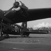 Looking for ideas and suggestions please, as first foray into such a large diorama for me, gulp 😆!! Please see images below - I am going to create a diorama to replicate Short Stirling MG-V W7445 at it's hard stand at RAF Oakington, with the LNER D16 locomotive and carriage in the back ground (I've purchased both) as seen in the B&W image below. My initial plans are to are cut out a "Trapezoid" that's 50cm across the front, 60cm deep and 70 wide at the back out of a solid foam, this gives it depth, width at the back and possibly a good composition too? . I am not going to use the frame that's in the image below with the paper cut out of the Stirling, that was way too heavy and large but it shows the concept. The rail track will sit at the back as the 70cm gives it the width for the D16 locomotive & carriage and the Stirling at the front, with it's front wheels on the hard stand and tail wheels on the grass behind. I'm thinking of using Balsa wood to create the edging of the foam. There will be a tractor and bomb trolley's, may be a vehicle and definitely figures working on the Stirling and loading Bombs too. It's Nov 1941, it'll be wet, even with a light snow here and there. Lots of Youtube info available, perhaps too much, so appreciate any suggestions? The scene below is what I'm thinking I'd like to replicate, though some bombs will be loaded and some being drawn up into the bay too. By Charles E. Brown - This photograph TR 36 comes from the collections of the Imperial War Museums., Public Domain, https://commons.wikimedia.org/w/index.php?curid=2050947
- 1 reply
-
- 8
-
-
- Short Stirling
- 1/72
- (and 1 more)
-
This is part 2 of my Kitty and Sledgehammer diorama. The Tiger got finished today so i made a start with this Russian howitzer. These things were used during the defence of Leningrad so it is pretty likely that the 2 models would have crossed eachothers path during the winter of 1943. This model is from Zvezda. And compared to the RFM tiger this feels quite different. The plasic feels a bit softer and there is a lot more flash and cleaning up to do. However the fit is decent and the details are good. The partcount is pretty low and there is no PE or decals involved. Pretty straight foreward building. And after an hour this is what i got as a start. The gun is dryfitted to check the angles. The lower frame consists of seperate parts so it is important to check the fit and to make shure all the angles are correct. That's it for now. I'll keep you guys posted. Cheers! 🍻🍻🍻
-
Hi 👋 Here’s a little 1/35 diorama featuring AK-Interactives FJ43 SUV with hard top built as a Toyota Land Cruiser. For the vehicle I added resin parts from Maconemodels and various extras from brands like PlusModels, Meng and others to pack the vehicle. The ferry is made from a Royal models bridge. Figures are from AK-Interactive, Bravo6, Industria Mechanica and MAIM. Say hallo to Kenneth 😁 Thanks for looking 😀 Cheers! /Fred
-
This project started out as a simple commission build to get my mojo back. After 2 failed ( imo ) projects i needed something to get the glue in my veins flowing again. It seemed to me that when ever i do a commission build, it brings the best out in me. So i took on this project featuring the T64 Bulat from Trumpeter in 1:35 scale. I really enjoyed their T72 so expectations were high. And i have to say this kit did not dissapoint at all! Trumpeter really produces enjoyable kits with a lot of detail without overengeneering things. And while i was building i got inspired by the Facade video's from uncle nightshift. I wanted to see if i could build a facade from scratch ( xps foam to be precise) And boy did that turned out to be a fun experience! I learned a lot of new tricks and this diorama base really helped me to enjoy this project as a whole. Although the final stages of this project weren't going as fast as i wanted due to RL obligations, i never felt bored out nor did i felt the need to rush this build over the finishline. So now this project is done..... time for me to take a step back and feel proud of how it turned out. Tomorow it's new owner is going to collect his newest addition to his modern armour collection. For now, time to clean up the workplace, enjoy the holidays and then i'm going to start with the German Armour GB on instagram. I recieved an invitation and i'm happy to join up. I want to thank all of you who take the time to read my buildlogs. Thank you for all your comments. I'm gratefull for each and every one of you. That the end of me ramblin' on. Here are the photo's Happy holidays!!!! 🎄🎁🎉
- 14 replies
-
- 34
-
-
-

-
 USN/RN Escort Carrier Deck & PSP Airfield Bases (70060 & 70059) 1:72 Arma Hobby Arma have a widening range of 1:72 kits, many of which would have flown either from carriers or temporary airfield, the latter having Pierced Steel Planking (PSP) laid over it to keep the mud to a minimum, as it is a huge impediment to operations for any aircraft. Both sets arrive in sleek cardboard packages that are folded around the injection-moulded bases, with a tab and slot keeping the wrapping in place, initially held firm by a length of tape. Once open, you can see the exceptional detail that has been moulded into these parts, each one measuring 15.2cm2, or 6” 2 section if you prefer, with a shallow vertical side all around. In addition, there is a QR code on the packaging that will lead you to a page on Arma’s site that provides 3D printer files to create some accessories to go with the base, on the assumption that you own an SLA 3D printer of course. The QR code on the base packaging offers bespoke accessories for the deck/airfield to accompany the bases, the parts appropriate for the type of base. The PSP base 3D files will print out fire extinguisher, toolboxes, fuel barrels, British ‘flimsy’ fuel cans, wheel chocks, and a wooden trestle, while the Carrier base has arrestor cable mounts, British and American versions of wheel chocks, and a bomb cart, all of which will add realism to your base and accompanying model (whatever you may build), with some careful painting. Markings There are no decals included in the boxes, as paint are all that is needed for these delightful bases, choosing suitable painted wooden and metallic shades where appropriate, with wear and a little rust if you choose. If you print the extras, some internet research will soon turn up some examples for paint colours. Conclusion The detail moulded into each of these bases is excellent, and once painted will be an excellent backdrop for your next model, or one that you’ve already built if that’s your intention. The 3D parts will be a boon to anyone with access to a printer, adding extra background interest to the model. Highly recommended. USN/RN Escort Carrier Deck (70060) PSP Airfield (70059) Review sample courtesy of
 -
I am proud to show off my completed Operation Overlord Maintenance Diorama. From start to finish, this entire project was completed in roughly 40 days. This diaroma is a mirror image of the Luftwaffe diorama I finished a little over a month ago. I tried to emphasize a more organized and functional scene with this build when compared to the Luftwaffe one since this would be later in the war. I used the following kits and accessories to build the diorama: MiniArt P-47D-30RA Advanced Kit 1/48 Eduard P-51B 1/48 Eduard Brassin P-51B Gun Bays Eduard Brassin P-51B Engine Additional 3D printed engine parts for P-47 MiniArt Field Workshop MiniArt Tool Set MiniArt Marston Mat Set Tamiya Allied Jerry Can Set Tamiya U.S Army Infantry At Rest Tamiya German Tank Maintenance Crew
-
And that’s a wrap! This 1/48 Luftwaffe maintenance diorama was by far my largest undertaking to date. It has assets from roughly 17 different kits and various components that I made from scratch. The following brands and kits were used: •Eduard Fw 190 A-7 Kit •Eduard Brassin Fw 190A-7 Engine and Guns •Eduard Brassin Fw 190A landing flaps •Eduard Brassin Fw 190A Wingroot Gun Bays •Eduard Look Fw 190 A-7 •Eduard Fw 190 D-9 Kit •Eduard Brassin Fw 190 A-4 engine •Tamiya Kubelwagen Type 82 •Tamiya German aircraft power supply unit & Kettenkraftrad •Tamiya German tank crew & field maintenance set •Tamiya brick wall, sandbag, & barricade set •ICM Luftwaffe ground personnel •ICM Luftwaffe pilots & ground personnel •MiniArt German fuel drums •MiniArt German Jerry cans •MiniArt Field workshop •MiniArt Wooden barrels Thank you to everyone that followed and supported the build along the way! The WIP thread can be found here - Completed thread for Fw 190A-7 - Completed thread for Fw 190D-9 -
- 24 replies
-
- 50
-
-
-
-

-
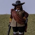 Outside one of the Gates of the Millennium Stadium (formally called something else for sponsorship reasons) in Cardiff is a statue of a bespectacled older gentleman. There are plaques on four sides of the statue's plinth. Each plaque is topped with his name: Sir Tasker Watkins VC GBE PC DL Three of the four plaques provide details on aspects of his life and the fourth his dates of birth and death (November 18 1918 to September 9 2007) and a quote from him. One plaque details his distinguished legal career, ending as Deputy Chief Justice of England and Wales from 1988 to 1993. One details his time as President of the Welsh Rugby Union from 1993 to 2004. The third contains a summarised version of his citation for the award of the Victoria Cross which reads: “On 16 August 1944 at Barfour, Normandy, France, Lieutenant Watkins' company came under murderous machine-gun fire while advancing through corn fields set with booby traps. The only officer left, Lieutenant Watkins led a bayonet charge with his 30 remaining men against 50 enemy Infantry, practically wiping them out. Finally, at dusk, separated from the rest of the battalion, he ordered his men to scatter and after he had personally charged and silenced an enemy machine-gun post, he brought them back to safety. His superb leadership not only saved his men, but decisively influenced the course of the battle.” It is this plaque that has inspired the build planned. I've been considering how best to do this. It turns out that Sir Tasker rarely talked about his VC and apparently refused to allow the Welch Regiment museum to display a painting of the incident that led to its award as he felt it ‘over-glamourised’ his actions. I thought any sort of ‘action’ diorama might be interpreted the same way. I feel therefore that it might align better to his views to depict the moment when he returned to battalion headquarters with the remnants of B Company; 27 men. Tired, weary men who had lived through terrible events; their officer amongst them but barely distinguishable. I therefore intend to use the below kits to try and represent at least a selection of those men and some of the vehicles that might be found at the battalion headquarters. I'll probably need to get more British Infantry. I hope that I can complete this diorama to represent in this GB not just Sir Tasker Watkins VC, not just the men of B company, but all of the ‘Poor Bloody Infantry’ who fought and suffered and died in Normandy. According to the Imperial War Museum “All seven infantry divisions that fought in Normandy had lost three-quarters of their initial strength by the end of August. The rifle companies had been the hardest hit. Though they formed no more than 20% of the whole, they had taken 70% of the casualties. In an echo of the First World War, junior infantry officers had a mere 1 in 10 chance of surviving unscathed.” https://www.iwm.org.uk/history/tactics-and-the-cost-of-victory-in-normandy I’ll leave the last words to Sir Tasker Watkins VC himself, speaking on the events that led to his Victoria Cross award, as quoted on the fourth plinth of his statue. "I did what needed doing to help my colleagues and friends and saw more killing in 24 hours than is right for anybody. From that moment onwards I have tried to take a more caring view of my fellow human beings and that of course always included my opponents, whether it be at war, sport or just ordinary life."
- 26 replies
-
- 14
-
-
-
Scaffoldings (49005) 1:48 MiniArt via Creative Models Ltd If you’ve been watching the procession of the new 1:48 diorama kits from MiniArt, you’ll have noticed that they’ve been applying their magic shrink-ray to the diorama accessories that they have been releasing in 1:35 over the last few years. This scaffolding set is one of those boxes, and while the box didn’t shrink, the contents did, so if you want some scaffolding for a project you have in mind, read on. The kit arrives in an end-opening figure-sized box with five sprues in grey styrene within. Due to the modular nature of the scaffolding, there is only one sprue design, and there are three assemblies to be made up, two that are basically the same but have the N-shaped tubular frames reversed to add strength to the assembly, the other a top platform with U-loop making up a perimeter. The parts are fixed to a bottom frame to create a ‘storey’ and have a ladder section attached to the bottom, and can be stacked as far up as the contents of the box allows, topping them off with a flat section of tread-plate, with inverted U-shaped brackets that give the user a modicum of safety. To facilitate movement of the unit there are four castors attached at the bottom, which have pedals to apply the brake once they are in position. These are moulded integrally as wheel, yoke and pedal, with ten in the box that can be used to complete two mobile bases with up to four additional layers of scaffold to make up, with a stack of three and two (including bases) shown on the box and in the build-up photos below, each with a standing area at the top, and some spare parts for the box. Conclusion A scaffold is a handy thing to have for any 1:48 diorama, whether it is tall or wide with planks or spare sections of tread-plate between them. They can be painted any colour you like, but a few examples are given in the instructions printed on the rear of the box, plus you can have some fun with wear and weathering effects. Highly recommended. Review sample courtesy of
-
I've started a new and very exiting project. Together with a couple of friends i met trough Instagram we decided we are going to do an Insta Group build. We all are making diorama's with the French early war R35 light infantry tank. In October we will present them all at SMC Eindhoven. I chose the version from hobbyboss. It comes with a full interior, PE and link 'n length tracks. My diorama will be set in a French village in the days before the german invasion of France. I ordered a streetcorner with house from RT-Diorama ( some of you may know the brand from the watermill video from uncle nightshift ) It's a plaster molded diorama base. I also order various figures, a tankcrew from Dynamo models and some cats and dogs. This will be a big project, by far my biggest diorama yet. So first things first: the R35. I started building the engine and gearbox. It's a tiny build and i discovered right away that this kit is not the best in terms of small parts. There is a lot of flash to clean up but the biggest issue is with the placement of the ejector pinmarks. Often they are in the most horrible places so they require alot of attention to carefully clean without breaking the part. The detail on the parts is decent and when a subassembly is finished it looks really good. There are some oddities in the kits instructions. For example: This picture shows a cut away in the main part. However: This is the actual part. Smooth as a babies bottom. To fit the tail light i had to alter the angel of the part to make it fit correctly. And that is the story with this kit. Most parts need additional work to fit Part D24 is way too thick so i had to sand it down to fit correctly on part B18. This kit forces you to dryfit, dryfit and dryfit again to avoid making mistakes or breaking parts. In the end it's nothing i cant handle. I enjoy the challenge but for people who are thinking of buying this kit, just don't expect Tamiya click'n fit. The interior is comming together nicely. The instruction want you to fit both sides at once but i decided to leave one side off to make for easier acces while building and painting. Here is the interior so far. And with the engine dryfitted in place. I had a good look at some reference photo's and i will try to recreate as much as possible so i will give adding engine wiring a go. In the end not much will be visible but at least i know it's there. That's it for now. Feel free to tag along, comment or stop by when you feel like it. I will try to make this buildlog a bit more extencive and post more of the process. I'll keep you guys posted. Cheers!!! 👍👍👍
- 56 replies
-
- 14
-
-
Hello! I am taking a leap into a ship and submarine diorama and now that Imgur is working again I can upload some photos of where I am. My idea was to have an upper layer of a flower class corvette sat within a thin but hard seascape that show above water and below water propeller wake including explosions from depth charges. Beneath that is another part of the dio, a submarine diving with air bubble trails and propeller wake with depth charge explosions around it in various shades / types of explosion profile with a North Sea base below……
-
Phu Bai Combat Base 1968 (53056) CH-54A Tarhe Helicopter, B-121 Bomb & M8A1 Landing Mat 1:35 ICM via H G Hannants Ltd With the advent of the helicopter, their ability to rise vertically into the air led them to lifting heavy loads, and by the end of the Korean War, there were already Heavy Lift choppers in service, most using piston-engines as their motive force, which was a limitation both in terms of power and reliability – a very important factor when you aren’t flying, but are instead beating the air into submission with your rotors. The peculiarly ungainly-looking CH-60 Mojave was reaching the end of its service life, and Igor Sikorsky had already identified the need for a very heavy lift helicopter with the S-60 that was powered by WWII era radial engines. The design was the basis for the Tarhe, but updated and given the more powerful and reliable turbo-shaft engines that were just coming into production. The engines for the nascent CH-54 were created in conjunction with Pratt & Whitney, adapting one of their new JT12 jet engines to their requirements. In an effort to keep the weight of the airframe down, the designers gave the Tarhe a cut-down skeletal fuselage, with only the crew compartment boxed in. This compartment also contained a rearward-facing cab that gave the crane operators an excellent view of proceedings, as well as limited control over the height and attitude of the airframe, as the CH-54 had an early form of fly-by-wire that allowed the duplicating of controls in a secondary location, but with the effectiveness of the controls lessened to reduce the likelihood of accidents due to sudden movements caused by the crane-operator. The advanced control system also gave it such luxuries as altitude control, reducing the workload of the pilots during extended hovers. The US Army recognised the potential of the type after a short testing phase, and took over 100 airframes on charge that would see extensive use in Vietnam. A civilian version was created too, called the S-64 Skycrane, while in army service it was often referred to as just ‘The Crane’. Because of its size, The Crane was capable of carrying enormous loads that were hitherto impossible to lift vertically, if at all. It was able to carry a Sheridan Tank, an M101 Howitzer, or up to 90 fully kitted out soldiers in a passenger pod that could be slung under the skeletal bodywork. There’s some fantastic diorama fodder right there. One of the more unusual tasks allotted to the Tarhe was carrying a huge 10,000lb bomb that was nicknamed the ‘Daisy Cutter’, although its proper designation was M-121. It was intended to explode above ground to clear landing areas for helicopters, but could also be used to clear foliage and enemy equipment, booby-traps and other unwanted obstacles away. It was packed with TNT and had an effective blast radius of 60m, but the shockwave could incapacitate or injure NVA troops up to 500m away. The Tarhe was an expensive method of delivery with limited range however, and the C-130 took over the job eventually, unloading the bomb via the rear load ramp. The bomb was superseded with a more powerful BLU-82 once stocks of the M-121 were depleted. The Tarhe was eventually withdrawn from service in the late 80s, as the airframes were ageing and the new Chinook was taking over in military service, the Tarhe finally leaving National Guard service in the early 90s. Due to their usefulness however, many of them were bought by civilian operators, especially Erickson Air-Crane of Oregon, who also took over type approval to ensure their ongoing airworthiness. The Kit This is a rebox of a brand-new tooling from ICM with a new sprue for the bomb, and to create the base from which the Tarhe operated, a sprue of M8A1 US Landing Mat and two sprues of figures have been included to depict the crew and ground personnel, giving you the basics of a diorama. The master tooling is the first of its kind in this scale, and in fact we’ve not been very well served in any scale as far as the Tarhe goes, other than an extremely old kit in 1:72 from another manufacturer. It arrives in a long top-opening box with a wrap-around painting of the type in action, and inside are a deceptive two lower trays with the usual captive lids, all of which is held in by tape. Take care when opening the box, as it could surprise you when the second box drops out. Once the boxes are open, the sprues have been spread evenly across the two trays to reduce the likelihood of damage to some of the lovely detail that’s within. There are twenty-one sprues in grey styrene, one of clear parts, a relatively small decal sheet, and a moderately thick instruction booklet printed on glossy paper with colour profiles in the rear. It’s difficult to get a feel for the scale of the finished model from the sprues, but the length is stated on the box of 774mm or 30.4” long, and 225mm or 8.9” tall. The width isn’t given, but each rotor is 28cm or 11” long, so allowing for the extra width of the centre boss it should be a little more than twice that wide. Detail is excellent, as we’ve come to expect from ICM in recent years, with finely engraved panel lines, raised rivets where appropriate, and crystal-clear canopy parts, which will be very visible on the finished model. Without a shadow of a doubt someone will manage to create a diorama that uses the cables to support the finished model above its load to give the impression of flight, and if they also manage to make the blades rotate, they may just achieve modelling godhood. Construction begins with the stepped cockpit floor, which is kitted out with rudder pedals for both pilots, adding the instrument panel and supporting centre console with decals to the centre, then fixing collective and cyclic sticks in position, followed by the seats that are each made from rear frame, seat pad and back cushion, locating in holes in their adjustment rails moulded into the floor. Another seat is made up from a solid base and two cushions, gluing in position on the lower section of the floor, facing aft and forming the first part of the crane operator’s cab. A partial bulkhead separates the front seats from the rear, adding another to the side of the seat that has a small console with joystick sprouting from the centre. Another L-shaped column is added on the inner side, and a short frame with an instrument panel and decal attached to it at the side of the cut-out, which is fleshed out with a pair of curved bulkheads. At the front of the cockpit, the nose cone is mounted in front of the instrument panel, then the sides and underside of the cockpit structure closes in much of the area. Turning the assembly around, the rear is closed in with a panel that wraps under the edge, and under the crane-operator seat, a foot rest with twin supports is slotted into the edge. The back of the cockpit has a lot of glazing, starting with five radiused panes in the starboard corner, one more on the port by the crane-op’s seat, and a large wrap-around section enclosing the operator’s cab. Much of the fuselage of this behemoth is skeletal, and is built up as a separate assembly, including internal bracing to ensure your Tarhe doesn’t become a Droopy. The process starts with the underside of the fuselage structure, which is made from three overlapping lengths that have location grooves for the bracing that comes later. Firstly, the winch is made from two halves that form a drum, capped off with two nicely detailed parts that turn it into a bobbin, which is supported between two angled trunnions that are each laminated from three parts, and braced at one end by rods and by the bobbin at the rounded end. It is glued between two vertical braces that have two more braces slotted in across the front and rear of the winch bay, fixing two exterior panels to the end of the cross-braces, plus another that is slotted in nearer the front. Take care here, as there are two slots, and the aft-most is the correct choice. At the same time, a cross-brace that supports the main landing gear sponsons is added from underneath, and this slots into all four thicknesses, as does another short brace behind and one more in the front, making the assembly stronger, and once it is glued to the underside of the fuselage it should be very strong. On the tapering tail section two more bulkheads are shown being added, but in the next step a longitudinal brace is shown already fitted, which I suspect is part D11, but test fit to reassure yourself when you build yours. The two tail sides with moulded-in fin hides the tail internals, joining together at the tip of the fin, and secured by adding the rear surface, and cutting a raised area off the underside. The topside of the fuselage is then boxed in with three panels, the largest having a hole in the centre for the rotor head later. The full length of the beast can be seen for the first time now, when you mate the cockpit to the front of the fuselage, gluing the side extensions to the bare section to create one assembly. An overhead console is decaled and detailed with levers, and is fixed to the rear bulkhead of the cockpit alongside another, after which the cockpit roof is laid over the area, followed by the windscreen and side doors that give your Tarhe a face. Two small two-part “ears” are made up and inserted in recesses near the rear of the cockpit, as are a couple of other small humps and bumps, the uses for which will become clear later. On the port fuselage side, a thick trunk of cables is fixed to the side and overlaid by a pair of C-shaped assemblies that are each built from three parts. The CH-54 had long legs that allowed it to pull its loads close to the spine to reduce sway, and these are next to be made, starting with a pair of two-part wheels, and the sponsons that support them, each one made from four surfaces, plus the struts, which have a two-part sleeve around the upper area, separate scissor-links and two tie-down hooks, fitting to the end of the sponson by the flattened rear of the outer sleeve. The nose wheel is also two-part, and fits on a short oleo with a one-part scissor-link under the nose. The winch head is also two parts and is added to the winch mechanism while the main gear sponsons are slipped over the supports and the nose wheel is put in place. The tail rotor head is a complex assembly that should remain mobile after construction, made up from eleven parts and fitted on the back of the tail fin along with a small bracing rod at the front. There are also several external trunks added individually on the starboard side and down the leg sponsons, some of which are overlaid by a protective panel near the front, and yet more small lengths are dotted around all over the place, making for a complex, detailed surface that should look more realistic than moulded-in alternatives. The drive-shaft for the tail rotor is also external, and runs up the back of the fin through some additional brackets, and terminating at the bottom with a four-part universal joint. More scabbed-on panels are fitted to the back of the fuselage, and a pair of optional aerodynamic fairings are supplied for the sides of the main gear sponsons. This isn’t even close to the final layer of detail yet, but we take a break from detailing to build the main rotor head next. The rotor-head starts with a bell-housing that has two input shafts from the twin turbo-shaft engines, the main portion of which is two parts, plus two-part end caps that is then placed on a circular base, and has the shaft cover and ring fitted to the top, adding a number of actuators and rods to the side, plus a housing with pulleys and equipment that mounts on the back of the head. The basic assembly is then mated with the opening in the top of the fuselage, after which there are a host of small wires/actuators/hoses that link the two assemblies together. A scabbed-on box is fixed to the fuselage behind the rotor off to one side to accommodate the drive-shaft for the tail rotor later, and a bulwark slots into a groove just in front of the rotor-head, followed by the drive-shaft, which slots through a support and dives through the tail to emerge behind the fin at the universal joint. A two-layer cover is placed over the drive-shaft around half way back, possibly to protect it from blade strikes, but it’s not the only piece of equipment that is sited on the fuselage top, which includes what appears to be a radiator assembly and some kind of exhaust, both installed behind the rotor-head, an area that is getting busy already. More parts are added further enmeshing the various assemblies, then it’s time to build the two engines. The Pratt & Whitney engines are identical in make-up until they reach the exhaust stage, which is handed. The front section is made from thirty-five parts before the handed exhausts are made, each one a mirror-image of the other, and built from eight more parts. The motors are mounted on the top deck with an M-brace between them, adding a few more small parts around them, then building up two intake filter boxes from sixteen parts each, handed to each side, with a scrap diagram showing how they should look from the front. They mount in front of the engine intakes on the ears we made earlier, and have two Z-braces front and rear between them. There are four auxiliary winches for load stabilising placed around the front and rear sides of the fuselage, with a four-part assembly making each one, and locating on a pair of brackets moulded into the fuselage sides. More detail is applied to the cockpit in the shape of four clear lenses underneath, a towel-rail and blade antenna, two more externally routed wires around the rear, and crew step plus three ladder rungs on each side, with two more around the rear. Grab-handles, door handles and windscreen wipers are next, followed by yet more grab handles on both sides leading up to the cockpit roof. More aerials are fixed at the root of the tail boom, and at the very rear, a three-part bumper is fitted under the fin, then an asymmetrical stabiliser is mounted on the opposite side of the fin to the tail rotor. Most traditional choppers have two rotors, and despite its size the Tarhe conforms to that layout, and the tail-rotor is first to be made, starting with the two-part rotor base that accepts the four individual blades, and a two-part actuator crown in the centre. It fits to the axle and should be able to rotate if you’ve been sparing with the glue. That’s the easy, simple part over with, now you must do it again on a much larger scale and with six blades. Work starts with the axle, the lower end of which slips through a centre boss and is covered by the six-point star assembly, which has another smaller star fixed to the centre, six D-shaped inserts added to the tips, and T-shaped spacers added vertically to separate the top rotor “star” from the bottom. The top portion is made up identically to the lower apart from the spacers, then it is closed over the rotor holders after gluing them in place on the lower. Each blade holder then has its four-part actuator mechanism installed over the top, and the whole assembly is topped by a three-part spinner cap. The final act is to insert each of the six blades into the holders, then drop the completed rotor into the rotor-head. The Bomb The bomb sprue can be found in its own bag, with the instructions buried in the booklet at step 189. It is built from two halves with a rear bulkhead, and when complete, it looks like a large shell. The retarding parachute pack is two parts that attach to the rear bulkhead with straps holding it in position, and the fuse is attached via an extender to ensure it lives up to its ‘Daisy-Cutter’ nickname and doesn’t bury itself in the ground before detonating. A short length of chain is made up from individual links that are put together without glue, using nine to create the connection to the aft shackle on the casing. The front shackle mounts on an eye that passes through the crane hook, and the whole assembly is fitted with bracing frame on each side. M8A1 US Landing Mat (210 x 336mm) During WWII, temporary airfields were quickly created near the battlefront on flat ground by the linking together of stamped steel planking that had the weight reduced by punching out holes in the centres where it wouldn’t weaken the structure. These were known as Perforated Steel Planking (PSP), and were used commonly in all theatres of war, reducing mud and slurry build-ups, and providing a flat and tough surface for aircraft to land, take-off and taxi along, and other vehicles were able to avoid creating ruts in the surface. The holes however led to an element of dust and debris being kicked up, which is known in aviation as Foreign Object Debris or FOD, so the design was changed to reduce the possibility of rocks and soil penetrating the planking. By the time of the Vietnam War, the M8A1 design had been formalised and was used to great effect. It was lightened by the use of corrugations to provide more strength from less material, and was capable of supporting the larger, heavier jet aircraft that were more prevalent. Lighter and more effective methods were developed later using aluminium, and latterly a honeycomb structure within that is incredibly strong, whilst reducing the amount of material needed. The set consists of four sprues, containing a total of forty-eight full planks, and sixteen half planks to accommodate an offset layout, or give it nice tidy ends. The ends of the full planks are joined by four pegs that link them together, and the longer edges have a set of simulated joints that are backed up for practicality by a series of small pegs and recesses hidden away on the lower edge, with the base flat and almost featureless to facilitate a strong bond with the substrate you are using as a baseboard. The instructions tell you to paint the planks in Gun Metal, number 1027 in ICM’s acrylic paint range. There is of course plenty of opportunity to weather them with rust and chipped/worn paint, so check your references to find your options. US Helicopter Pilots (1960-70s) There are four figures in this set, two of whom are wearing traditional crew overalls of the era, while the other two wear standard fatigues, with their sleeves rolled-up to counter the heat of their typical arena of operation, Vietnam. All figures are standing, while one pilot has an arm and leg out as if stepping up to the entry of his aircraft, and both overall clad crew have shoulder holsters with a sidearm that is a separate part attached to the junction of the straps under one arm. All the figures have peaked caps, and some can be holding a crew helmet that is found on the smaller sprues in two halves, joining up down the centre to create the hollow inner, which has ear cups for comms moulded into the lining. There are two subtly different styles of helmets, one that has no visible equipment around the sides of the face, and another that has clasps for oxygen masks or other equipment to the sides, and there are two of each type available. All the crew have flat tops to their heads for the caps, so if you decided to make them wear the helmets, you may have to do a little padding to get the correct ‘sit’ on the pilot’s head, or just add a blob of filler to simulate the rest of his head. The parts for each figure are found in separate areas of the main sprue for ease of identification, and parts breakdown is sensibly placed along clothing seams or natural breaks to minimise clean-up of the figures once they are built up. The sculpting is typically excellent, as we’ve come to expect from ICM’s artists and tool-makers, with natural poses, drape of clothing and textures appropriate to the parts of the model. Helicopter Ground Personnel (Vietnam War) This set holds a single sprue of grey styrene within, an instruction sheet that’s printed on both sides in colour is inside the main booklet, along with a flyer for their acrylic paint range that debuted some time ago. There are four figures supplied on the sprue, two of whom are standing to inspect their charge, one leaning over for a better view. The other two are kneeling or sitting, the kneeling gentleman inspecting something low down, while the other chap is sitting atop a winglet on the box top, screwdriver in hand, contemplating his next move in repairing or maintaining the engine compartment he has open. This last figure is the most kit-specific, but could easily be re-tasked by adding a box or platform of suitable height under his backside to give his stance some support. The parts for each figure are found in separate areas of the sprue for ease of identification, and parts breakdown is sensibly placed along clothing seams or natural breaks to minimise clean-up of the figures once they are built-up. The sculpting is typically excellent, as we’ve come to expect from ICM’s artists and tool-makers, with natural poses, drape of clothing and textures appropriate to the parts of the model. Seamlines and stitching have been engraved into the surfaces, making detail painting easier, and more rewarding to the eye. There are no decals provided for the figures, but over the page from the sprue diagram and paint chart are four drawings of the figures in colour, with part numbers supplied in black, and paint codes in red boxes that correspond with the chart and give codes for ICM’s own paint system, plus the generic name of the colour in question. It also lets us know that ICM’s acrylic boxed set #3023 can be used to paint the figures, which you can find in our mega review, scrolling down to the appropriately numbered set. Markings There is just one decal option on the sheet included on the sheet, and unsurprisingly, it’s green. Many of the decals are for the blades, but there are also national and airframe markings, plus the instrument panel decals and some stencils. From the box you can build the following: 67-18416 with M-121 bomb, 478 HHC (1st Cavalry Division), Phu Bai Air base, Autumn 1968 Decals are by ICM’s usual partners, which is a guarantee of good registration, sharpness and colour density, with a thin gloss carrier film cut close to the printed areas. Conclusion This will make a superbly detailed model, and its size will draw some admiring or envious glances if you take it to a show. Detail is excellent, construction is sensible, and it is a new tool of this monstrous machine. Did I mention it also has a massive bomb? Add the planked base and two sets of figures, and it should make for a lively diorama with a few extra sundries dotted around it. Very highly recommended. Available in the UK from importers H G Hannants Ltd. Review sample courtesy of
-
Hi, It's the last submarine I built:, HMS Astute (Hobby Boss): . . . . . . The sea made of resin... Chris
-

My first Sea Diorama - Revell - Type VII C/41
Bill1974 posted a topic in Work in Progress - Maritime
Hiya all This is my first water Dio and I'm hoping to learn alot and prepare myself for a couple of high detail ship / sub dioramas that I have planned. I have already built and painted the sub, it was soooo tiny that I feel a bit silly posting photos of what was a few pieces and a little glue, not really taxing (apart from being small!) So this build will focus on the water..... A starter for 10. (A big fan of old school university challenge) Comments and suggestions welcome 🤓👍- 53 replies
-
- 12
-
-
-
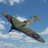 This project was made as part of the D-Day Group Build. This is my first ever diorama and it's made up with a lot of other firsts. First Typhoon, Panther and Tiger kits, first tank(s) for many, many years, first plane kit in flight, first use of a Prop Blur, first use of aftermarket decals (for the Typhoon) and first 1/72 figures. Nearly everyone who contributed to the WIP thread helped with ideas for the building of various elements of the project so a big thank you to them all - it wouldn't have been possible without the help of the BM team. Also it was seeing Kallisti's Typhoon base that got me thinking about doing a diorama - so thank you to Kallisti for the idea. Typhoon: Airfix 1/72 Mk.IB Typhoon (new tool version) - MN526/TP-V - No.198 Sqn., 123 Wing, 84 Group, 2 TAF B10/Plumetot, France - July 1944. Panther: Dragon 1/72 Ausf G with Zimmerit, no. 135 of 12 SS Pz, Tiger I: Dragon 1/72 Ausf E with Zimmerit, no. 131 of sSSPzAbt 101 German and British troops from Ceasar Miniatures Baseboard: Softwood, Sundela, MDF, filler and various leftover scenic materials from model railway projects made a long time ago. The WIP can be found here The RFI for the Typhoon can be found here The RFI for the two tanks can be found here Time: early evening, July 1944 - Location: somewhere northwest of Normandy This last photo shows the actual diorama and the background I used to give it depth. The background is actually the display shelf I made for my Spitfire builds but it seemed to work well as a backdrop - I thought it would look better than just a plain wall. Although this project is finished as far as the D-Day Group Build is concerned I've still got some ideas for developing this diorama further but I'm going to make a couple of Spitfires first! Thank you for looking. Comments and suggestions welcome. Kind regards, Stix
- 50 replies
-
- 32
-
-
- D-Day Group Build
- Diorama
- (and 3 more)
-
Clear Box (100-Box01) Special Hobby Storing your models can be just a case of putting the finished work on shelves in a cabinet or on an open shelf, but that leaves them open to damage by incautious hands/paws, and of course, the dreaded dust. Dust has a habit of resolving itself over time into a self-adhesive layer that’s best not thought too deeply about, in case we realise what it consists of. Display cases are usually some combination of quite expensive, heavy or not of the required size, so it’s hard to find one to fit your modelling output. This new clear-topped display box is about to change that, particularly for 1:72 or smaller armour builders, or anyone that needs a display box with 5cm of headroom, measuring 13.4cm x 7.7cm at the base, internally, tapering to 12.8cm x 7.6cm at the top of the box interior. It has a clear upper of course, or you wouldn’t see much, and a black plastic base onto which the top fits neatly, although not tightly. If you grip the clear upper, it will come away without effort from the base, so to keep the atmosphere out, you’d need to glue/seal the two halves together with an adhesive that won’t mar either component. The black base has a lip at the bottom on which the top rests, and a bevelled edge around it that extends diagonally 8mm into the base. This gives 12.1cm x 6.5cm of useable flat space on the base, which is ideal for 1:72 armour, 1:43 vehicles and other such reasonably-sized models. The box arrives in a clear shrink-wrap film, with a sticker on top telling you what it is, and in the process it protects the case from scratch damage in transit. There is nothing stopping you from adding ground works to the base, the diagonal section adding a separation between your diorama/vignette and the clear sides. You must ensure that you don’t use any solvent-based adhesives or putties to create your masterpiece however, for fear of melting the base, and you should also ensure that all paints, glues and potions have fully cured before you drop the lid on your model for eternity, as it’s possible that off-gassing could result in partial melting, or frosting of the clear top, ruining your case. That’s for you to look out for however, as most cases are plastic, and the same rules apply unless you can afford glass cases. Conclusion A simple, effective and cost-conscious way to protect your creations from dust and ill-advised touching from fingers or paws. Fingers crossed that some larger boxes will arrive in due course. Highly recommended. Review sample courtesy of
-
 Hello to all. I know I’m going to be really late for this one but really want to finish my entrophy build before I begin properly (this build it’s a bit ambitious and not sure if I’ll finish but have been looking forwards this for a long time). Anyhow… here’s what I’m approaching: Similar to John masters diorama in that it has several figures and vehicles. Hoping it’s ok to have all three in one thread as they will be appearing all in the one very small simple dessert base. Shot with instructions and still unopened sprues: the tomahawk 2b from academy: the open box to the right is the aml resin/pe set I got from a fellow Brit modeller; Im really really not a plane guy. As I’ve said before I know next to nothing about them just like the way other modellers make them. So I’ll probably lean on the knowledge bank within this gb quite heavily. I’ve only done a couple 1/72 planes before… but will give it a try. This will be a shark mouth, box art colours from 112 sqn. Then it’s something I’m a bit more familiar with: Tamiya damiler dingo mk2: Should be a bit of a quick one. Going to do this in the Mike Starmer guided light stone and dark brown wave pattern. I’ll post up refs a little later. This one comes with two figures but on top of this I’ve gone and got two absolutely stunningly crafted white metal figures from David Parkins: It’s really hard to track down British desert figures in 1/48 but they are beyond beautiful for their scale. Lastly the Tamiya crusader. I’ll be doing the light stone and black pattern in a mk1: I like the mk1 with its funky little mg mini turret, you don’t tend to see to many: I have a wardrawings camo plan which I’ll follow. I’m actually away at a show and brought this kit with me as theirs no tv In the hotel room 😱 so I made a start below: The wheel made up and tidied. The lower cast metal hull screwed to the the part sone upper hull. And that’s it so far. I like the weight the metal base gives and this time will make it hard for me to screw up the running gear alignment… something I’m magnetically drawn to do… I just love it, I mean I can’t actually build something without a wonky wheel or track hanging loose somewhere…. Maybe I should trade mark that? 😉 Anyway it’s called wondering into the blue as that’s what the raf used to call the desert, the blue. The idea is of a pilot who has had some sort of mechanical issues which has caused him to land in the desert. The dingo and crusader were out looking for the pilot (crusader their for extra protection and to possibly tow the plane back to base?). They come across the plane but no pilot. He has left a note, which I have mocked up on the pc and will stick to the side of the base. The note will give very British cryptic clues as to his journey back to base, figuring if he stays with the plane he’ll die without trying to get home. Thanks all, Paul
- 54 replies
-
- 16
-
-
- Brush painted
- Desert scheme
- (and 1 more)
-
Hi, I've decided to start Trumpeter HMS Eskimo in 1/350 scale.: . . I use WEM photoetching... and Black Cat models set. Chris
-
 So this is my Tamiya halftrack diorama. It depicts a german infantry unit taking a bit of a break during the battle in France. You can find the buildlog here: https://www.britmodeller.com/forums/index.php?/topic/235132104-tamiya-hanomag-in-france-without-the-krupp/ It was a joy to build this model. In typical tamiya style all the parts went together really nice. The model lacks a bit of detail and i think i will build a second halftrack in the future using a kit with a bit more detail. I used figures from Alpine and Miniart. There is a difference in molding ( details are a bit crude on the miniart figures ) and also in size. The Alpine figures are much more refined and a joy to paint. The miniart figures are ok but need much more work to make them look half decent. The diorama base is a complete scratchbuild using styrofoam and various AK diorama products. My first attempt to make water flowing down looks a bit rough..... Overall i'm happy with the look of the whole scene. I kept the weathering light, a bit of dust and some streaking but nothing over the top. Thank you all for stopping by and taking the time to look at the photo's. All comments and or tips to improve are welcome. Still struggeling a bit with the photo settings. There is something to learn too. On to the next build. Something german named 'Moritz'
- 17 replies
-
- 33
-
-
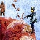
 Well...it's not often I post here. There is so much going on in this diorama I constructed for the ongoing 'I Feel Deserted' GB that I don't have enough space in the GB gallery thread for all the photos I would like to post. So I will post more here. Here is the WiP, by the way, if you care to look at it. It explains everything. Lots of pictures... I like my rocky outcropping... That's it! --John
- 22 replies
-
- 38
-
-
-
I found this in the internet and just loved the scene. As you can see two fairly bored looking Germans guarding the wreckage of a MK V ( no it is a Mk Ia and thankfully my plans are too ) Spitfire. I’ve chosen 1/35 because I have quite a few Tamiya figures in the spares box in that scale, and it rather scratches the spitfire than attempt to scratch figures. First off some plans, scaled to 1/35 and printed. Next up some woodwork. After some time with my detail sander a coat of polyurethane ain’t to see where we’re going. I’ve cut out the engine bay and cockpit area and skinned the whole thing in 20 thou plastic sheet. Next some more spitfire work and a bit more carpentry
- 38 replies
-
- 16
-
-
So had this idea for a while, this is my third build for the group build, this is only loosley based on the images below, but the idea is a sunken fighter wreck from WW2 long abandoned and now an attractive place for kayakers and free divers in the shallow waters of Nikko Bay Paulau. Its a 1/72 Airfix A6M Zero, converted to a Rufe Floatplane Fighter thats been sunken when it was hidden in the quiet secluded inlets of Nikko Bay in 1944 and forgotten, time hasnt been kind to the wreck and although lightly damage when sunken, scuttled perhaps, time and salt water has started to eat the structure away.
-
Hi, This is my last diorama, The USS PAUL (KNOX class) on the French Riviera. It's the Orange Hobby kit (USS Robert E. Peary), the water's made with resin: . . . . . . . . . . . .Chris
-
Folks , Next entropy project is Golan Guard, a 1:72 diorama that will show the last resting place of the last of a long line of Stug III assault guns. TBF from my research its not very clear if they even got a shot off during the 6 day war in 1967. Im going to use the video below as the basis of the project, I have a Revell Stug III G, be aware am using this as a basis similar to the Mig Dio, its not meant to be an exact reflection. I will need to try and figure out how to 3D print an interior and stuff. Let the fun begin 😆