

Stickframe
-
Posts
630 -
Joined
-
Last visited
Content Type
Events
Profiles
Forums
Media Demo
Everything posted by Stickframe
-
Beemax Lancia S4 1/24 "Henri Toivonen"
Stickframe replied to Vesa Jussila's topic in Work In Progress - Vehicles
Hi Vesa, Some nice and clean building going on here! I understand your concern that the pattern on the decal might look a bit out of scale, but you managed to get it to follow the contours nicely, and it looks really good! Looking forward to your next post Cheers Nick -
Vincent Motorcycle Gunga Din scratch build
Stickframe replied to albergman's topic in Work In Progress - Vehicles
Thank you for posting so much of your process - this is very interesting to see, and it is certainly coming together nicely. Cheers Nick -
Mercedes-Benz 1628s Tractor and Low Loader
Stickframe replied to JeroenS's topic in Ready For Inspection - Vehicles
Hi Joroen, This is certainly a sharp looking rig and trailer - great finish on all! and against your backdrop it really looks the part! Beautiful job on the scratchwork on the trailer. The little bit of color on the ratchet straps, reflecting tape and lights looks nice against the black. Looking forward to seeing your "shorty" tanker truck! Cheers Nick -
Well guys, sort of a funny day - did some zoom calls, emails, and so on for "real" work, and had more time than I guessed for the big Pete - Speaking of "big Pete" - man, that breakfast sounds pretty good! I might just walk on down to my neighborhood cafe in the morning and go for some pancakes and coffee!! 😄 It could be a treat - supposed to rain all night - a good reason to break out the umbrella and go for a stroll! And back to serious business, I kept going on the rear end. During this phase of work, the tasks ranged from getting it to work ,to getting it to look right - both important, but as it's only a model, both required some head scratching. As you all know, there are limitations that come from scale - you can't "just" do anything as the parts are small and there are not scale welders, grinders, cutoff tools, ratchet straps, or ratchet wrenches - instead, giant fingers, huge knives, lots of Tamiya tape, sanding sticks, glue, optimism and enthusiasm 😄 In the spirit of this, on we went with that sassy Hendrickson rear end: Sheesh - there is plenty going on here - I finally figured out the right geometry between the walking beams, drive shafts, brackets, and control/pivot arms from each diff to the chassis cross member. I wish I could report that I came across some clear and logical answer or keen insight, but - no, just an instinct to declare that it was done. This "inspired" conclusion was driven by the reality that this is indeed a model being built with no instructions, dimensions, or "replacement" parts - time to hope for the best. With that declaration made, it was time to figure out how to make it look right - the relatively easy part was adding nuts and bolts - a bit tense, but not too hard to do. The bigger challenge, as noted by @stevehnz, was getting the required rubber blocks in place. To clarify this, as you can see above, in the area circled in red, this suspension (should) include rubber blocks between two steel parts - but, a guy doesn't have those handy.....what to do?? After a fair amount of pondering, we came up with the idea that rather than installing a solid piece of material between the two plates, two opposing parts would be installed. That is, two thin pieces of styrene, on the top and bottom, that don't align with one another would be glued in place. This would allow the appearance of a solid surface, but as the two parts are offset from each other, the walking beam could tilt, and suspension could move! Well, I was pretty happy with this idea! Next step will be to add some really thin styrene rods to the plates to make them look more convincing. Another minty treat was adding the "Transverse Torque Rods"....yeah - the two rods that extend from the axle to the chassis. Happily, the KFS kit had some rods - not intended for this exactly, but I can adapt. As you can see above, a guy installed some alu square tube to the axle, then attached said "Rods" to the axle brackets, and eventually connected them to the chassis. And installed: I wish I could report that installing this was easy and went smoothly - it wasn't and it didn't 😄 The common model builder's lament - if I had another hand or two, but like each of you, on we went. Once the basic assembly was in place, went ahead and built some receiving brackets for the torque rods, attached them to the rods from the axles/diffs, and glued them in place. The biggest surprise was that it still flexes - not quite as much as before, but pretty fine with me. In the morning I'll add (fake) torque rods, front and back (in the area with the red circle. Ok, time to go to bed - those pancakes are on my mind - lol - thanks for having a look cheers Nick
-
Hi Jeroen, This will be fun to watch. Building the tank should be interesting to see. Will you extend the chassis or keep it really short? Every now and then, I see short chassis trucks running around - short dump and flatbeds - and think they look pretty cool - though I have wondered why put such a small load area onto such as big truck? They look good anyway! Cheers Nick
-
Hello guys, @stevehnz, hi Steve, you could well be right! I am hardly a big truck expert, but do enjoy building models of them. As I was getting going on this, I did some homework, but hardly scientific or through - and along the way, I found this image from Hendrickson that caught my eye. It's unclear to me how they achieve this much flex with the rubber blocks - adding to this, I have since seen several concrete mixers with this in use, which don't suggest something with too much flex 🤨 This is the prototype I'm going for. Now that I have been working on this for a while, It seems the rubber blocks themselves don't "give" too much, but because the bracket and axles have pivot points, some flex may be achievable. I really don't know! I appreciate you taking some time to join the discussion - as it seems you know about trucks, please keep sharing some thoughts on this! I don't want to make any giant blunders as we go! @JeroenS, Hi Jeroen, the u-joints are some no-name variety I found on Ebay. They are intended for use on RC vehicles, and while a bit out of scale, heck, they are fun to use and were not expensive! They use tiny allen studs, and it turns out the wrench for these is more expensive than the u-joints. I didn't buy the wrench, and instead used a fine point, magnetic phillips head screw driver, then sealed with some CA, a bit like locktite! Cheers Nick
-
Hello model builders, @JeroenS and @keefr22 - how about those ti/yres!! yes, they are pretty hefty! As always I really like KFS products. These were a bit uncharacteristically chunky, so they received some attention from the sanding block, to round off the edges and level out the tread. @Vesa Jussila, yes, there is plenty of scratch work here, and I must say that includes lots of head scratching! While the KFS axles are in use, I wound up adding new tabs for the walking beams and cutting off the others, which is fair enough, as this rear end was supposed to be used for another kit - 🤨 😄 Well, my beloved SF 49ers didn't play today, so I kept after this truck. I spent all day working on two brackets! How hard could that be? well, maybe not all that hard, but certainly slow going. Nonetheless, after building and tearing apart a few times, some progress was made: While new to me, this suspension has apparently been in use for quite a while, so with some effort I was able to find photos and even some diagrams. But, as none of these are dimensioned, I took a different approach to getting the dimensions that would result in a flat chassis. Basically, propping the rear end up to match the front with tires and wheels in place, then measuring the gap between the top of the walking beam and the bottom of the chassis rail, then adding the thickness of the chassis and walking beam. You can see the layout in the lower left above. Next, I measured the length of the clevis' I'm using to allow this to pivot (the square space you see on the two images to the right. It turns out the bracket is mounted on the outside, then filled to match the thickness of the walking beam. Sorry if that was to windy an explanation - hopefully the pic in the upper left clarifies this. Oh - you'll also note those fancy pants U-joints. Well...they're in - but they put up quite a fight - both in terms of adapting them to driveshaft and pinions, and in getting the length to work and not fall out! There is a slip joint to allow flex, but it turns out, the geometry of the two trailing/control arms affects the geometry of the driveshaft, and alignment of the entire rear end - how do I know that? see below: Ahh, more model building good times....as you can maybe see in the photo on the right, the walking beams are not parallel to the chassis rails! And the driveshaft fell out each time I tried to make this work. Why???!! well, I measures all of it for square - check - so why??? The front trailing arm was about a millimeter longer than the rear. Obviously 😄 So, out it came, and I cut it down and made a sleeve, like a slip joint yoke and that seemed to do the trick: As you can see, it now sits level. I still have to add lots of detail to those brackets, like the diagram, but at least the overall system seems to work. Sort of funny, took a few minutes to type this up, and all afternoon to make it work 😄 And below, it still flexes. I came very close to giving up on this - as the driveshaft dropped repeatedly, and only the rear end would only tilt upward on the forward side - annoying: And above, you can see, it still tilts and flexes. So, a productive weekend, thanks for having a look Cheers Nick
-
Hi Jeroen, ha! yes, we are speaking the same language - I simply could not pretend not to see -- 😄 So, this is how they turned out: "a guy" simply couldn't abide the other version! 😄 these still need some sanding, but they are better! Now, back to Billy big rig - and the rear suspension. My plan was to convert a KFS rear end that seemed close - and well in concept, it is close, but in application, and with big tires, not good: Well, not ideal - the tandem tires are too close, so, I extended the KFS control arms, and experimented with length until it looked right: Hmm - as you can see in the red circle, the kit control arms are too short, so I lengthened them - first too much, then cut them back - the photo on the right is not correct. I cut 2mm off each and they worked ok. Then on to the walking beams: As I didn't have walking beams, a guy went ahead and made them. I have a nice diagram of what these are supposed to look like, so laminated several sheets of cut .040" styrene together to make them. It's 62 mm from centerline of bushing to centerline of bushing for this model. A bit slow going but more or less correct. I might beef them up as we go, as they just look thin. That said, they work. And as to why I chose this suspension: You can see plenty of flex. But, next up will be making the bracket to hang this from the chassis. Which brings to light two problems - I think I can keep the dramatic pivot using some extra brass clevis connections I have - but, as both of these are drive axles, I'll need to make some flex on the driveline too. A while ago I purchased several small scale u-joints, intended for RC kits - which might work here - don't know just yet! OK, thanks for having a look - Cheers Nick
-
Hi Dan, Beautiful and inspiring work - really a pleasure to see! Cheers Nick
-
AMT '65 lowrider Grand Prix
Stickframe replied to Pete in Lincs's topic in Work In Progress - Vehicles
Ha - "Who's gonna drive you home?" the Cars of course, in a sassy low rider! Took me a few looks to understand your nerf bumpers - got it! and looking good! Cheers Nick -
Hello model builders, Billy big rig here again - I simply could not abide those fenders. So, a guy went ahead and changed them: So the first step was to figure out what was wrong - the outer curve was thin, and the inner, sitting too low on the hood side. So, as you can see above, went about fixing these. Next, adding a new outer shell: And now, slightly more credible fenders! The "skin" is very thin, at .010" - so, touching it up with some Tamiya white putty - which unhappily is a bit dried out, so not all that user friendly. However, in the end - better than where we were. OK, I feel better now- Cheers Nick
-
So, back at the shop I'm still playing Billy big rig! 😄 "Real" work was slow for the last few days, so deeper into this I went. Hi Jeroen, I appreciate your optimism! They are coming together. I find I have to be really careful with restraint, that is, to know when to stop sanding, if it is "exactly" right or not - lol Hi Vesa, appreciate it! It's also turning into some serious head scratching - - 🤨 😄 Hi Houston, well, thanks very much! I also appreciate your optimism, will be useful as we keep after it! Hi Andy, appreciate that comment, but - you know - you think it's just right - and alas, well, it's not - lol - I can live with it! First up, I walked out for lunch about an hour ago, and this happened: A nice comparison of two different Peterbilt tractors! the key differences being the hood and fenders - I am trying to do something like the red version - Looking at this, and thinking about the comments above, I don't think my fenders have enough swoop/big curve high on the side of hood sides - again, I'll live with it! - or not, maybe keep adding to the fenders? not sure just yet. But, other areas are coming along - first up, the front spring pack and attachment to the axle: As you can see - lots of different materials going into this - the springs look tiny compared to the tires and axle, but are about 50" (scale) inches long! and that's 7 leafs! if will ride like an ox-cart! And - what to do about the chassis? The chassis is the laser cut kit from KFS - and you can see the black kit chassis in the foreground. This is turning into a big model!! I went with the shorter version - only because it's shorter and I might be able to get it to sit nicely on a shelf somewhere when it's done. So - this suspension, is a challenge. The axle leaf pads are just wider than the chassis rails, so the brackets are mounted projecting from the chassis - but, hidden within is a cross member to mount the engine near the oil pan, and the engine mounts toward the bell housing, need to be slightly lifted inside the frame rail to work. Getting this more or less correct will allow the cab to fit, and the hood to tilt. The kit includes a giant CAT engine, and huge radiator. The truck I'm building uses a smaller Paccar engine...and different radiator. So - nothing fits as is. Also, the hood hinges are mounted on the outermost part of the horns, above the front leaf spring hangers.....good times. As you can see the engine is only taped in, and I'll need to modify the kit fan, make a new shroud, and save what I can of the radiator. But, it works! happily for me, the front axle is indeed centered on the fender well opening! I shot these two for scale - this is a big model - long and tall. With the front end installed - less steering etc, I decided it was time to start thinking about the rear end - challenge 1, axle width.....: And above, the lower axle is the front with leaf springs attached, and the upper, the rear axle on the left you can see the tires I'm using - and the hubs required, but, they don't fit and are too narrow on the axle. In the upper right, well, the axle and hubs that fit - but, of course, don't fit the wheel. So, these will be spliced together, and the obvious goal, to get the front and rear axle/wheels to be about the same width. Then to get after the walking beam suspension. Ok, that's all for today - thanks for having a look and happy model building, Cheers Nick
-
HI Jeroen, this looks great! I spent last week in remote parts of Pennsylvania and New York, and could easily image seeing this car racing along those wet country roads, or parked along side an old shed! I like the light dusting of road grime, like driven right after the first light rains of the season. And, the engine and bay looks great! Nice build! Cheers Nick
-
Hi Model builders, Jeroen, I thought you might like this one, as you too like making the big rigs! Not too much to share, but I have made some progress on the hood. First up, some framing: Unhappily, there is not much contrast in these photos, but hoping you can make out that I added some styrene to get the basis for the bigger fenders found on these tractors - And yes, I eliminated the flat spot on the arc in the image on the upper left. What you can also see is a .025" segment of rod which curves along the side of the hood side. This is used to mount the thin sheet used to make the fender inner arc. It turns out the overall form of the top of the fender is concentric, so the kit parts are modified to achieve the right look: Again, unhappily, there is not much contrast evident, but you can see the fenders taking shape. There is a sheet of .010" sheet laid over the previously shown frame work. I've added putty and will sand to get a uniform surface. As the hood and cab don't have a uniform base height (ie I've tried to "test" tilt, but can't really achieve the alignment/movement), I am not sure of exactly how the hood will tilt without hitting the cab? But, I did angle outward the edges of the fender framing, to allow for some clearance - we'll see.... Next up, the frame and suspension. I'm using an old set of KFS laser cut styrene channel to make this. I'm not sure of how long to make it but, will figure something out. Then, will start with the front leaf spring packs and axle. With that built, I'll be able to set the rear suspension height. Thanks for having a look - Cheers Nick
-
Peugeot 405T 16GR Dakar - 1/24 Tamiya
Stickframe replied to bradeq's topic in Work In Progress - Vehicles
I really like this build! nice attention to detail -adding the right things in the right places! Cheers Nick -
HI Keith, Thanks, and I hope so! Check back in a week or two, hopefully will have an update - Cheers Nick
-
Hi Jeroen, your engine bay looks great - you really nailed it! You mentioned the orange peel, from the photos it doesn't look too bad. I saw your note on the previous page that you didn't wet sand etc. Aside from being a bit brighter, I wouldn't be surprised if the paint might look like what you'd see on a 1:1 after so many years? a daily driver? Slotted wheels look nice too! I'm looking forward to seeing this when you're done! Cheers Nick
-
AMT '65 lowrider Grand Prix
Stickframe replied to Pete in Lincs's topic in Work In Progress - Vehicles
Hi Pete, this is coming right along! I like the stance too! It looks like you're getting the T-bird rear lights to fit in cleanly too I was interested in seeing what you might do back there. Cheers Nick -
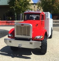
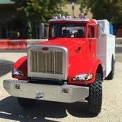
Hello model builders, Well, as things would have it, I started this project. I wasn't planning on getting going for a while, but as I sat and watched my beloved San Francisco 49ers choke through and eventually lose today, I started building. A week or so ago I began seriously looking at info and doing some research on this project, which is to make a Peterbilt six wheel drive heavy or medium truck, It will have a bed of some sort, rather than a 5th wheel, but I don't know what will be in that bed. I prepared some images of what I'm planning to do. First, please see some reference images of the prototype(s): So, a guy decided to make something like one of these - and while not as mighty and majestic (😄) as a Kenworth 6x6 oil field truck, I think these examples are just fine, and I like the looks of Peterbilts. But, as no such kit exists, I'll need to scratch and kitbash my way through. Note the height difference between the Peterbilt 365 in the upper left, compared to the conventional tractors next to it! I have an 1/24 scale Peterbilt 378, which is a a long-haul highway tractor - not an off-road rig - at all. But, it is what I have, so I prepare this little study: And short of reciting all of those points, what you will find is that the current Peterbilt truck (the 367) would be really hard for me to achieve - I really pondered giving it a go, but just don't think I can (as noted above, there are several BIG differences with my donor kit), which is a bummer because I really like the looks of that truck. This leads me to the older 3 series tractors, which share the same (basically the same or similar to) the 378. The 365 is a heavy duty brute - but, for a build, it might not be all that challenging (for the bodywork) so, I'm opting for a 382 or 348 - which have the same hood, but different engine. Key to the build is the front axle: As shown above, the truck I'm modeling will have a solid front drive axle - the lower two images are of a 348, while the upper two from a 365. For this, I'm starting with a KFS axle, but I'll scratch the leaf springs and suspension. Also, note the single tires on the rear axles on the 348 in the lower left corner - I'll use singles too. For the rear end, well, something completely new to me. Below you'll see a Hendrickson walking beam tandem rear suspension - but, note no air bags or leaf springs - just rubber pads at a pivot point. While new to me, this has evidently been around a while - and is well suited for rough terrain and a good candidate for some scratch work!: Hopefully these images are understandable - the "walking beams" are a pair of solid arms, on each side of the chassis, that are connected to the axles. There are bushings where they tie to the axles, so there is rotation and the beams pivot from a central point where they mount to the chassis of the truck. So, I'm going to try and build them. I have two KFS axles, which, aside from being for a heavy duty tandem, are almost exactly unlike the setup! a good challenge! As noted above, I was not planning to do anything on this for a while. But, as the game was depressing, I did - and started the hood: I built a Pete 348 once before, but from a different donor kit. In this kit, as you can see in image 1, you get a one piece hood with fenders. So, while trying to ignore the demise of my 49ers, I got to thinking about how to convert this hood. Step one, I left it and it's chunky connecting points on the sprue, to assure some degree of alignment stability for what I was about to do. Last time I bult the whole thing from scratch - a lot of complicated work. This time, a conversion. The Tamiya tape (figure 1) is my cut line - as the 348/382 hood slopes and as you can see, the 378 doesn't. But, before cutting it apart, I built front and rear frames, to support what I planned to be a scratch built cover (figure 2) . Turns out though, that I could modify the part I cut off and reset it (figure 3) what a surprise! And below, you can see how it turned out: It now has a slope! While not easy, this relied on visual comparisons to photos, and not a rigorous analysis, primarily because I wasn't planning to start this as soon as I did. Turns out, it was a LOT easier than scratch building all of it. That said, it worked out pretty well: Above, you can see a cutout of the hood comparing it to a 382. Note: I didn't forget the concentric design on the fenders! just haven't start them yet, and below: The hood is superimposed on the truck on the left - the base images is of a 348. So, we're off. No building this week tho. Work will have me tied up, so maybe back at it next weekend. Thanks for having a look - Cheers Nick
-
Toyota FJ45 Rock Crawler
Stickframe replied to Stickframe's topic in Ready For Inspection - Vehicles
@Toryu, thanks very much - glad you like both! @Anteater, thanks, and I agree with you - after spending time building a project, I have fun getting ready for the RFI 😀 I prefer outdoor photos of my projects - the colors really pop. Earlier this year I began experimenting with backdrops for use with a diorama - and now, well, I feel pretty good about the presentation technique, but still haven't finished the dio!! there you go....and of course, I'm pondering a new project, and still not that excited about the dio! 😄 Cheers Nick -
HI Andy, Sorry to hear the news of your real car - seems you were lucky with only the blown gasket - not an overheat and ruined engine parts! The model is coming along nicely. I don't think you're alone with the temporary stoppage of work on a project - it's taken me a few months to get reengaged too. Looking forward to seeing this wrapped up - oh - i like the reuse of the exhaust collector on your exhaust manifold/header! great idea! Cheers Nick
-
Caterpillar D7 3t crawler tractor 1/76
Stickframe replied to Bbdave's topic in Ready For Inspection - Vehicles
Very nice CAT! looks like someone is still crawling it through the fields! or with that big winch, the forest! Only thing it's missing is the bailing wire used to hold loose parts in place! Cheers Nick -
Hi Keith, wow! What a finish! looks great. Every now and then I'll see one of these running around the SF Bay Area - and as mentioned above, they are sure small! Folks bravely drive them through city streets between buses, trucks, bikes and all! Cheers Nick
-
Beautiful build! great finishes and photography! actually, a remarkable finish! Cheers Nick
-
1/24 Terrible Transit Camper RFI
Stickframe replied to Anteater's topic in Ready For Inspection - Vehicles
This looks great! some years of good fun showing through! Cheers Nick


