Witold Jaworski Posted August 5, 2019 Author Posted August 5, 2019 I use my models in visualizations. However, they are released on a CC license, so you can use them as a 3D reference when you prepare a game model, paper model, 3D printing model, or a new moulding form.
Putty Animal Posted August 6, 2019 Posted August 6, 2019 Very interested to see how you get on. This sort of research fascinates me. I tried to import the linked file on the Fokker D.V to blender in the hope of getting a 3-view drawing that I could slip into my windsock datafile on the aircraft. Unfortunately I'm a duffer with that sort of thing. Does anybody know how to manage it?
Witold Jaworski Posted August 6, 2019 Author Posted August 6, 2019 Thank you! About creating 2D drawings from Blender: this is not so easy, because Blender is a program for creating animations, still images, and similar artistic stuff. To produce ("render") a result image you have to prepare the scene, set up the lights and assign appropriate material to each object. Of course, you can generate an orthogonal image with all edges outlined using special orthogonal camera and render settings. For example - below you can see the SBD model, rendered in this way: (This is the earlier version of my model, without the engine and exhaust stacks) Of course, such a setup is more natural for composing a painting scheme (below you can see the same model, but covered with realistic textures): (this is an aircraft from VB-16, as it was in the beginning of April, 1944) However, maybe for your purposes it will be easier just to make a screenshot of the side, front and top view from the Blender screen? Here you can find an introduction to Blender 2.7, which describes the basics, in particular - how to navigate in the 3D space of this program. Important: it describes the previous Blender version (2.7). At this moment the current version is 2.8, which uses an easier, but different interface. If you have installed Blender 2.8, you can download the Blender 2.7 which was used for the Fokker V and described in this introduction, use one of these links: Blender 2.7, 32-bit (a *.msi installation program) Blender 2.7, 64-bit (a *.msi installation program) (You can have different Blender versions on the same computer without any problems).
warhawk Posted August 22, 2019 Posted August 22, 2019 Your 2D representation in the first image looks great. Given the amount of work You have put into getting everything right, would it be possible (and, of course, relatively easy) for You to make orthographic 3-views of Your SBD model just like that? This would make a great reference for us to scale and check our kits against.
Witold Jaworski Posted August 22, 2019 Author Posted August 22, 2019 Indeed, some time ago made these orthographic views + tricolor painting scheme of the SBD-5. They are still missing the engine, exhaut stacks, cockpit interior, and many external details, especially on the bottom of the wing. Nevertheless, they still can be usable as the aircraft geometry reference. Here are links to the high-resolution SBD-5 images: Side view Top view (left wing set without the dihedral, allowing for precise measurements) Bottom view (right wing set without the dihedral, allowing for precise measurements) Front view (missing engine) Rear view Painting scheme (the same as in the previous post, but in the higher resolution) If you find them useful, I will be grateful for a mentioning my site (http://airpanes3d.net) Below some comments to these drawings: Of course, some of these details may change when I got the original Douglas documentation from NASM. However, I estimate that the maximum error of drawings from this post should no exceed 1 inch.
Witold Jaworski Posted November 11, 2019 Author Posted November 11, 2019 Finally (after 5 months) I received the Douglas SBD microfilms from NSAM (7 rolls). I have already contacted a local service provider, who scans microfilms for museums. They promised me to scan them in the beginning of December. (I have no any microfilm viewer, and do not want to spoil these films in a slide projector. At this moment I just checked that the title page of these microfilms says that this is the Douglas SBD/ A-24, and that it contains blueprint pictures). I will keep you informed on the progress. 3
Kushan_Farsight Posted December 2, 2019 Posted December 2, 2019 @Witold Jaworski - some amazing, and incredibly detailed work going on here. I am sure there would be quite the interest in the hobby field for a digitized copy of your Douglas Microfilms! Realizing youve got this far with Blender just doubles how impressed i am with this project. Looking forwards to the next update!
Witold Jaworski Posted March 27, 2020 Author Posted March 27, 2020 (edited) In June 2019 I followed C. West suggestion and ordered a set of Douglas SBD original technical documentation from U.S. National Air and Space Museum. Technically these blueprints are stored on several microfilm rolls. In that time all what I knew about this package (NASM id: “Mcfilm-000000408”) was the information printed on the order form: As you can see, this set has no index, which I could order earlier to examine its contents. When I finally received these microfilms in November 2019, I also discovered the meaning of enigmatic “(roll C” in the item description: it was truncated phrase “(roll C missing)”! Well, this set was incomplete, but anyway I ordered its high-resolution scans from a local company that provides professional microfilm scanning services to museums. In January I received these data (4700 high-res, grayscale images in LZW-packed TIFF format – in total, about 300 GB). Finally I was able to scroll these blueprints. Frankly speaking, I was afraid that the most important drawings were lost with the missing roll C. Fortunately, during the initial review I noticed many detailed assembly blueprints among the scanned images. I even found a complete inboard profile of the SBD-5: Here you can download the high-resolution version of this inboard profile (about 70MB). The scanning company (Digital-Center, located near Poznan) did its job well, adapting the scanner resolution to the size of the depicted drawings. Scans of frames that contain large assemblies are usually 11 296 px wide and 7 874px high, which ensures that even the smallest references are readable. For example – see these four subsequent frames of the fuselage assembly drawing: 1, 2, 3, 4 (beware: size of each of these linked images is about 70MB). There are even larger images in this result set: the biggest one is about 20 000px wide. The smaller drawings of various details are scanned at 7 672x5 682px. Conclusions from the first review of this microfilm set are as follows: Roll A: blueprints of various small elements. Many of them (various angles, straps, bolts, pins, etc.) are standard Douglas parts, shared between many aircraft types. (As the angle from Figure 107‑5 – it was traced in 1936, before the SBD appeared on the designer desks); Roll B: blueprints of various SBD details - special bolts, pins, screws, various brackets, supports, forged parts, some minor assemblies (for example – arresting hook); Roll C : missing Roll D : assembly drawings Roll E: more detailed assemblies, some larger details Roll F: remaining elements (this is the shortest roll) Roll XA, XB: updated drawings, published a few months later. Most of the drawings are duplicates of those depicted in rolls A-F, but can differ in minor details. However, some of these drawings are new – most probably they are updates of the drawings from the missing roll C; These blueprints describe SBD-4 and SBD-5 (which is OK – the SBD-4 is similar to SBD-3, and SBD-2, while SBD-5 is nearly identical to SBD-6). It seems that rolls A-F were made from September to October 1943, while their updates – rolls XA, XB – in January 1944. Because of the missing roll C, this documentation is not complete. In general I could not find the fuselage ordinates (I only found the wing ordinates). My first impression is that the missing roll C contains most drawings of wing ribs and at least half of the fuselage bulkheads. Fortunately, there are drawings of the tail bulkheads and the firewall on the other rolls. For my project I need to organize these blueprints into a tree-like structure, with the largest assemblies in the root (as described in this post). However, after this initial review I could not determine the rules of the drawing numbering system used by Douglas. (I wanted to use them for quick grouping all parts belonging to the same subassembly). It could happen that in this Douglas factory the drawing numbers were assigned sequentially, just as the subsequent blueprints were ordered! It also seems that some of these drawings use original Northrop numbers, dating from the SBD predecessor: the BT-1 dive bomber. To organize this documentation I have to start from the general assembly drawing and then step down to its subassemblies. For this purpose I need an index of these blueprints. Recreating such a thing is a monotonous task that will take some time, but I cannot see better option to fully explore contents of these microfilms. What’s more, I think that once such a list is created, it can be also useful for the others. While NASM forbids publishing technical drawings from their microfilms by any means (except so-called “fair use”, which I am stretching a little in this article), I still can publish such an index. Of course, I will also donate its copy to NASM. I hope that in this way the eventual future buyers of these SBD/A-24 microfilms will benefit from my work. First obstacle in creating such a drawing list is quite unusual: while most manufactures traced the digits of drawing numbers in ink, as the all remaining drawing lines, Douglas stamped them in the title block. The ink often spilled over the edges of the stamped digits, and now it is hard to read them from the microfilms photos. For example – look at the title block of this sample drawing: When I altered the gray shades of this drawing, I was able to identify the first four digits (5063): Fortunately, after this adjustment I discovered that they also stamped (most probably) the same number on the right margin. So here it is: 5063493. (You can also find a mirror image of this number on the right below: most probably it was stamped on the other side of this drawing). Of course, sometimes even these additional stamps on the margins are hardly readable: I frequently wondered whether a particular “splash” in place of a digit represents “4” or “1”. In other cases it was difficult to tell if there is a “3” or “8”, or “5”, or even “0”. Some help came from the observation that the numbers of these microfilm drawings are always in ascending sequence. Thus, if the unreadable digit in the drawing number “519456x” can be “3”, “5”, or “8”, but the previous drawing is “5194560”, and the next drawing is “5194565”, then this last digit must be “3” (giving drawing no: “5194563”). Still there are cases in which I was unable to decipher the drawing number even after adjusting the grayscale, and there was a wide gap between the previous and the next drawing number: The standard parts, like the one depicted in figure above, often occur in several variants (you could cut the depicted standard angle in a variety of lengths). In such a cases Douglas placed in the drawing an example of the full part number: The prefix of this part number is the drawing number! In case of unreadable dedicated part/assembly drawing numbers, Ester A. from AirCorps Library suggested the “last resort”, indirect method. Usually the blueprint of a non-standard part contains a table named “NEXT ASSEMBLY” on the side of the main title block. It provides drawing numbers of the assemblies that use this part: In the case from figure above this is a single assembly drawing: 3063922, which was used in the SBD-1, -2, and -3 models. Using this drawing number I found the corresponding blueprint: Examining this assembly drawing, I found the sought detail and read its number. Of course, this method requires searchable list of the available drawing numbers, from which I would read that drawing 3063922 is in roll B, frame 1014. That’s why in the first step I needed to create the drawing index. It took me about 100 hours of work, but here it is: Click here to download the index (*.xlsx file, 303kB). Frankly speaking, for my purposes I do not need the details from roll A, which took about 25% of the total work time. But I decided to index all the rolls, just to provide a complete list for eventual other users. Below you can see how this list looks like: For each microfilm frame I note in this table not only the drawing number, but also the name copied interim from the drawing title block. (I preserved in these texts original caps and the grammar errors – for example: “PILOTS CHAIR”). Eventual unreadable digits in drawing numbers are marked as “?”, and unreadable text fragments as “<…>”. It seems that in Douglas numbering system drawing numbers of standard parts should have “S-“ prefixes. However, I found that these prefixes were often missing, or even manually written in drawings of certain parts that do not seem to be standard. Thus I decided to skip “S-“ prefixes in the numbers placed in this index, because they could be misleading and make the eventual searches more difficult. Instead I marked each drawing of a standard part in the Comments column, basing on the presence of the “STANDARD PART” statement in its title block. When a single drawing spans over two or more subsequent microfilm frames, I described it in the index table in following way: Each line in the table represents single microfilm frame, thus drawing 5196835 is described by two subsequent lines, which differ by the drawing frame number in the Partial frame column (1, 2). In the first of these lines I placed the roll id of this drawing (“E128”). I did this just in case, because I do not think that I will use these ids. I placed drawing description (title) in the line that corresponds to the frame containing its title block. In this way the table contents is more readable. (You can instantly recognize for each drawing where it starts and ends). In this list you can use Excel filtering feature, searching for drawings that contain certain phrase. When you click the auto-filter button in the right corner of Description column, and search for “BONDING” phrase, you will get following result: If you did this search because you wanted to find the drawing of the fuselage bonding, in the result set you will see the last line of drawing 5196835 (the one that contains the description from its title block). You can read the roll symbol and the frame number from Roll and Frame # columns (roll: E, frame: 193). From the Dwg frm column you will learn that this is frame 2/2, thus you will also know that previous frame (192) from roll E contains the first part of this drawing. Finally, figure below shows one of the most complex examples of a multi-part assembly drawing: A very long drawing 5094762 (E138) was originally traced in two parts (1/2, 2/2). Each of these parts spans over 3 frames and has its own title block, thus I placed their labels in the corresponding index lines. What’s more, this assembly is accompanied by additional BOM tables, depicted in the subsequent microfilm frames (6, 7, 8). Edited March 27, 2020 by Witold Jaworski 4
Witold Jaworski Posted April 20, 2020 Author Posted April 20, 2020 In general, the set of 7 SBD/A-24 reels from NASM contains 3308 unique microfilm frames, belonging to 3022 drawings. On reels “XA” and “XB” you can usually find updated copies of the previous reels (“A”, “B”,.. “F”). However, 350 frames from “XA” and “XB” are unique – most probably this is a part of the missing roll “C”. Duplicates from these “X*” reels are also useful, when a drawing from one of the previous reels is unreadable. I chose about 1000 frames (mostly assembly drawings) from this microfilm set, and organized them into a tree-like structure as in figure below: To preserve disk space, I placed in these folders shortcuts to files located in the original directories (These original directories correspond to microfilm reels: “A”, “B”, …, “XB”). I practiced that when I click such a link, it opens the image in Photo Viewer, as if it was the original file. I think that Douglas did not use any sophistical drawing numeration (at least in this project). The SBD/A-24 drawing numbers seem to be assigned as they were ordered: for example, drawing numbers of subsequent wing bulkheads belong to number series that begins with: 206*, 209*, 212*, 406*, 409*, without any visible order. Maybe this is due the fact that part of these drawings came directly from the Northrop Co, without any renumbering? (You can still find “Northrop Aviation Division” name in the title blocks of some standard parts from this microfilm set). The documentation from NASM microfilm is missing many important details – I suppose that they were on the lost reel “C”. For example, figure below shows the identified and missing wing bulkheads: Fortunately, reel “E” contains also wing geometry master diagram (ordinals), so I can use it for recreating shapes of these missing elements. Fuselage structure also misses many bulkheads: However, there is no master diagram for the fuselage. I will have to recreate its shape basing on the few reference dimensions placed in the identified assembly drawings. I have also found some contours of these missing bulkheads, drawn as additional information in various installation drawings. However, these blueprints are not as precise as you think – due to barrel distortions of the photo lens and draughtsman mistakes, I estimate their tolerance to 2-3% of the overall size. Unfortunately, there are no data about the wing fillet shape, especially its outer edge. Several years ago I analyzed the SBD photos and concluded that SBD-5 (and -6) engines were mounted a few inches forward than in the previous Dauntless versions (SBD-1..-4). In this post I estimated this difference in length as 4 inches. Now I found the proof of this observation in the SBD-4 and SBD-5 engine mount dimensions (drawings 5055954 and 5159336): The explicit dimension of SBD-4 engine mount (dwg no 5055954) specifies its length (distance from the firewall to the back faces of the engine mounting lugs) as 34.1875 (I switched original fractional dimensions to decimals). Similar dimension of the SBD-5 engine mount (dwg no 5159336) declares its length as 38.1875. Thus we have the 4” difference! However, to determine the ultimate difference in the fuselage length (marked in the figure above with the question mark) I also have to determine the overall lengths of the elements in the front of the engine mount. Both versions (SBD-4 and SBD-5) used the same propeller (length: 21.75”). From the drawing of the SBD-5 NACA ring I can read the overall length of the entire engine cowling: 60.8125” (see figure above). Unfortunately, there is no such information in the SBD-4 drawings. I have to determine this dimension in an indirect way. Let’s try it. The blueprints show that the length of the NACA cowling was identical in all versions (31.5”), as well as the distance from the R-1820 cylinders plane to the front of the NACA ring (14.3125”). (The NACA ring was attached to the mounting points on the R-1820 cylinder heads. These points were placed on the engine cylinders plane). Thus the potential source of the eventual further fuselage length differences is the distance from the back faces of the engine mounting lugs to the cylinders plane. From the SBD-5 blueprint I can calculate that it was 8.3125”. This result is close to the dimension specified in the R-1820 installation drawing (8.24”): However, this installation drawing describes the R-1820 G200 (also known as C9GC), which was used in the SBD-5 under military designation R-1820-60. (For more information on the Wright “Cyclone” engine variants see this post). The R-1820-52, used in the SBD-4 and earlier Dauntless versions, belonged to the earlier R-1820 G100 series (also known as C9GB). Crankcase of the G100 family significantly differs from the crankcase used in G200. This could also mean differences in the coaxial location of the engine mounting lugs. The B dimension marked in this drawing is the piston bore. This is well-known parameter of this engine, specified in the manufacturer documentation as 6.125”. I can estimate the sought distance A by comparing it to known B. The A/B ratio that I measured in a high-resolution copy of this drawing is 1.286 (+/- 0.8%). This means that A = 7.875” (+/- 0.063”) – i.e. the same distance as in the R-1820 F. I assume this value for the R-1820-52as as the most probable distance from the mounting lugs to the cylinders plane. Thus the overall difference in the SBD-5 and SBD-4 horizontal lengths comes from the difference in their engine mount lengths (4”) and the difference in the distance from the mounting lugs to the cylinders plane between the R-1820-60 and -52 engines (8.3125– 7.875) = 0.4375”. This result can be rounded to 4.44” (or expressed precisely as 4 and 7/16”). According Douglas general arrangement drawing, the overall length of the SBD-5 was 33’ 1/4” (396.25”). Thus the overall length of the SBD-4 could be 32’ 7 13/16” (391.81”). What about the earlier Dauntless variants: SBD-1, -2 and -3s? The eventual difference in their lengths and the SBD-4 length comes from the different propellers. (They used “Hamilton Standard Constant Speed”, while the SBD-4 used newer “Hamilton Standard Hydromatic” propeller). In the NASM documentation I found a powerplant diagram (dwg no 5094793), which shows this older propeller variant and the contour of its spinner. Although the spinner shape a little bit different than in the archival photos, all other drawing elements seem quite precise. Using this picture I could make a more precise estimation of the few key dimensions: In this blueprint (above) I identified vertical lines that mark the firewall and the engine mounting lugs planes, as well as the cylinders plane. I scaled the distance between firewall and engine mounting plane to the corresponding dimension (34.19”), then I read the B, C distances, and – just as additional check – the A distance. I received: B = 37.66”, C = 42.38”, A = 7.88” (which confirms the previous estimation: 7.875”). Thus the overall length of the SBD-1,-2, and -3 can be estimated as: when the spinner was mounted: 32’ 6.3” (+/- 0.3”); without the spinner (the case often observed in the archival photos): 32’ 1.5” (+/- 0.3”); It is interesting that p. 2 agrees quite well with the SBD-1 and SBD-2 length (32’ 2”) listed in the BuAer performance data sheets from 30th November 1942 (an repeated in many other later publications). Quote The aircraft dimensions listed in these BuAer data sheets are rounded (up?) to full inches. For example: the wing span is listed as 41’ 7”, while the exact value in Douglas arrangement drawing is 41’ 6.25” (41’ 6 1/8”). Similar (single) BuAer sheet from 6th August 1942 examined the SBD-3 and SBD-4. The horizontal length specified in this document (32’ 8”) agrees quite well with the length of the SBD-4. We can assume that in the sheet which examined both: the SBD-3 and SBD-4, BuAer engineers simply put the length of the latter (evidently they treated these two aircraft as a single variant). Quote Many publications cites SBD-3 length as 32’ 8”. This is wrong value, coming from overinterpretation of the BuAer data sheet from August 1942.
Witold Jaworski Posted May 16, 2020 Author Posted May 16, 2020 (edited) Actually I am preparing data from the original Douglas blueprints to verify my model. For the beginning I chosen the wing. This is a well-documented assembly, because I found a master diagram in the NASM microfilm that describes SBD wing geometry (ordinals). Below you can see the first sheet of this diagram (dwg no 5090185): Here you can download its high-resolution version (5MB). As you can see, it contains the ordinal tables of the wing bulkheads (ribs) and webs (spars). In the sketch on its right side Douglas engineers depicted various other dimensions of the wing center section. In the picture above I marked in red its key wing stations. Their names correspond to spanwise distance in inches from the aircraft centerline: “STA 10” is 10” from the centerline, while “STA 66” is 66” from the centerline. Another part of this diagram contains a sketch of the larger, outboard wing section: Here you can download its high-resolution version (7MB). Wing station names of the outboard section starts with “STA 66” and continue to the tip, which is named “STA 251.06”. This distance – 251.06” – is measured spanwise, along the reference planes of the outboard and center wing sections. The first thing that I noticed comparing these blueprints to my model, are the different reference planes: For my model I chosen the airfoil chord as the reference plane, with the origin point at the tip of the airfoil nose. (Airfoil coordinates are specified in such a reference system). The SBD wing was inclined at 2.5°, thus I rotated my wing object by the corresponding angle. However, from the photos I learned that SBD webs (spar) planes were vertical, so I adjusted their directions in my model. (If they were also inclined at 2.5°, connecting webs to the fuselage bulkheads would be much more complex, i.e. heavyweight). In the original Douglas diagram shown above you can see that its engineers took different approach: they used re-calculated airfoil ordinals for given inclination angle. In this way their reference plane crosses the wing trailing edge and remains parallel to the fuselage centerline and perpendicular to the web planes. It seems that it was a standard approach in that era: I have found similar solution in the original Curtiss P-40 blueprints. Building my model, I used simplified stations diagram from the SBD Maintenance Manual. From that diagram I knew that the wing tip station was at 251.06”. I also correctly assumed that the station distances are measured along the corresponding reference planes of the center and outboard wing sections. In principle I was right, but I assumed wrong reference plane for the outboard wing! Below you can see the plane that I assumed for my model, and the real reference plane from the Douglas master diagram: Usually designers choose reference planes along an easily distinguishable element, which you can use as the base for physical measurements. Their choice is extremely important for the technology used in the manufacturing (i.e. ultimate product cost), because these reference bases are reflected in the tooling geometry. In the case of the aircraft wing the most obvious candidate for such a base is the trailing edge. However, in this wing Douglas engineers chose a strange reference plane, which fits to nothing! Look at the fragment of Douglas master diagram above: every spanwise line of the wing is oblique: trailing edge, leading edge, upper wing contour (1° downward), lower wing contour… It does not even fit any spanwise contours of its webs (all of them are trapezoids). There was no chance to discover such a thing without this master diagram blueprint! Quote However, I knew that there is something wrong with the geometry of my wing. To obtain the dihedral angle specified in the SBD Maintenance Manual (in the front view: 7.5° along the wing upper contour) in my model I had to raise the outer wing section by 10.2°. For such an angle, I obtained wing span of 496.4”, which is 1.73” short of the documented value. I checked again station locations, to make sure that I did not made an error. I found nothing wrong, thus all what I could do was just to compensate this difference by additional 0.86” offset to each wing. (In picture above I marked it at station 66). Now it is clear, that this difference was caused by the wrong choice of the reference plane. In the master diagram this wing is already “pre-rotated”, and you have to raise it by only 8.5° to obtain the proper dihedral angle. I also made another error. Building the wing model I assumed that declared, 15% thick airfoil NACA2415 at station 66 (joint of the center and outboard wing section) was perpendicular to the reference plane of the outboard wing (i.e. to the wing airfoils chords plane – see figure above). In the effect, I obtained the oblique rib (10.2°), adjacent to the wing center section, as 15.24% thick. Now from the STA 66 ordinals of I learned that they used the 15% NACA2415 for the oblique rib, thus the real wing was somewhat thinner than in my model. I recreated the ordinals from the master diagram as polygons in 3D space of my model. These are all five webs and some key ribs. You can see their arrangement in figure below: In the picture above the ribs seem to be smooth, but look at the enlarged nose of STA 138: their vertices (ordinals) are connected with straight edges. Note also see fragments of the master diagram image placed on the reference plane. To easily place rib polygons at their stations, I used single reference plane for both wing sections (i.e. the outer wing has no 8.5° dihedral). Thus at this moment the outer section is minimally raised above the reference plane, as it was according the ordinals. You can see this arrangement better in the picture below, taken from another viewpoint: For the outer wing section I also recreated the ordinals of theoretical (i.e. in this arrangement - vertical) STA 66 contour. However, this is just a wire (a “theoretical entity”) – because the real rib at outer STA 66 was oblique. Figure below shows the wing tip contour geometry specified in the master diagram: The rear part of this contour (from point A to B) is shaped by an arc, which radius is 33.62”. The forward part (from B to C) is a free-form curve, described by a few key points, dimensioned in this drawing. Quote In this drawing you can see an auxiliary reference base, placed at 38.705” from the basic reference plane (located at STA 66 nose tip). This additional reference was introduced to facilitate dimensioning various wing tip details. The master diagram describes this line as “common percent line”, perpendicular to aircraft centerline. In trapezoidal part of the wing it connects points located at 33% of their airfoil chord lengths. For initial verification of wing tip contour, I also placed over this fragment the assembly drawing of the wing tip. You can see the result below (lines from the master diagram are blue, from the assembly drawing – black): In general, both contours match each other, within the tolerance of the manual sketching and eventual later deformations caused by microfilm camera lenses. However, the shape of aileron cutout significantly differs between these two drawings. What is interesting, photos of the restored SBDs confirm the variant depicted in the assembly drawing. Quote The width and height of the basic grid “square”, visible in this and further pictures in this post, correspond to 1 in. In this assembly drawing I also identified additional rib (bulkhead) at STA 229.45. It did not occur on the stations diagram. However, the SBD wing tips were demountable, so its presence just at the joint seam is quite obvious. (The rib at STA 228 was its counterpart from the other side of this seam). I placed on this drawing the free-form curve key points, following the explicit dimensions specified in the master diagram, and connected them with a curve. I was surprised, discovering that the central part of this contour does not fit both drawings: The difference between these contours is quite significant and reaches about 0.4” near the auxiliary reference plane. All what I could do in such a case was checking this detail in the available photos (especially the archival photos). Unfortunately, it is impossible to precisely compare this shape with the perspective images of real wings. That’s why I focused on the contour of the running light base. In the assembly drawing its forward part elevates a little above the win tip contour, while according the master diagram curve there would be no such elevation. I can say that you can observe such an elevation in most of the restored aircraft and in all of the archival photos. They confirm the wing tip shape depicted in the assembly blueprint. The same applies to the small deviation from the master diagram contour at the aileron tip. It would be difficult to bend the end of the tip edge ring precisely around the master diagram “mathematical” arc contour, because of the sudden change in the curve radius at point B. (In that era aircraft designers cared only about the tangent continuity of their theoretical contours). What’s more, the master diagram does not specify many other wing tip geometry details, for example – it misses the cross-section radius of the wing tip edge ring. To determine it, I had to use the detailed drawings of the wing tip webs. Ultimately I verified the wing tip shape using all available images of its parts: I have found some further differences between the wing tip webs and ordinals of STA 246. (This is the last wing station, specified in the master diagram. Most of its shape is purely theoretical, because only its central part corresponds to a real partial rib). I also found some other, less significant differences in the center wing section (for example – in the middle of STA 10). Finally I concluded that the master diagram describes an initial concept of the wing shape, which was later (in the prototype workshop?) slightly modified, especially at the wing tip. Thus in all these cases I decided to rely on the assembly drawings. Below you can see the complete “reference structure” which I prepared for the SBD wing: Around the leading edge I placed a long, bent cone, which reflects its varying radius. Similarly, I signalized the radius of the trailing edge by marking it with two thin “tubes”. According the flap assembly drawing (dwg. no. 5066078) the outer radius of the flaps trailing edge cross-section was 5/32” (which means that they were about 0.3” thick). Aileron trailing edge was somewhat thinner: according the master diagram and assembly drawing the radius of its inner wedge was 0.09”. Because the SBD ordinals do not include the eventual skin thickness, I had to assume that sheet metal used as the overlay in the aileron structure was 0.05” thick. In the result I obtained the ultimate thickness of aileron trailing edge as 0.28” (2*0.09 + 2*0.05). I also added other details, as the landing gear wheel bay and aileron hinges axis (both dimensioned in the master diagram). Before matching my model to this “3D reference frame”, I decided to check at least one of its overall dimensions – just in case. The most obvious candidate was the wing span, which I could read from the general arrangement drawing: 41’ 6⅛”: Note that it was measured precisely between the tips of the curved wing contour: the widths of the running lights (1.5” for each side) were not included. (The width of these running lights was specified in the front view of this drawing). I also noted that the SBD maintenance manual specifies slightly different wing span: 41’ 6.3”. More precisely: according dwg 5120284 the distance from the center plane to the wing tip was 498.125”/2 = 249.063”, while the maintenance manual shows it as 249.187”. The difference: 0.124” on each side of the aircraft was minimal, but this wing was identical in all Dauntless versions. Which of these dimensions is wrong? I made a quick calculation using the stations diagram: if the distance to the wing tip measured along the reference planes was 251.06”, then the half of the wing span is: 66 + (251.06-66)*cos(8.5°): The result is 249.03”. However, the SBD ordinals describe “skeleton geometry” and did not take into account the skin thickness. Thus I have to add to this result the typical thickness of the wing skin: 0.03”. Finally it gives distance of 249.06”, which perfectly agrees with arrangement drawing 5120284. Reassured by these calculations, I raised the object representing the outboard wing in my 3D “reference frame” by 8.5°, and measured the distance from its tip to the center plane. I was really surprised by the result: Well, the reason for obtained dimension – 247.60”, instead of 249.03” – is simple: in my calculations I did not take into account the initial elevation of the wing tip over its reference plane: In the result of the rotation by 8.5°, the wing tip is 1.43” closer to the aircraft center than STA 251.06, placed on the reference plane. Quote As you can see, the location of the of the SBD outboard wing reference plane is so unusual that even Douglas engineer, who provided dimensions for the arrangement drawing, made the same error as mine. Thus the true wing span of the Douglas SBD was: 41’ 3.2” between the wing tips (i.e. between bases of the running lights); 41’ 6.2” between tips of the running lights; Note that without the arrangement drawings you can easily make another error, and compare the wing span provided in the most of publications (41’ 7”) with the distance between the tips of the running lights. The result you will obtain in such a case will be quite close to the real value, because these two errors compensate each other. Quote Wing span from the SBD maintenance manual (41’ 6.37”) is also wrong. Was this slightly higher value (249.187” instead of 249.063” from dwg 5120284) obtained by adding the sheet metal thickness of the tip lights bases? On the other hand, in the practice the precise overall wing span was seldom or never used. During production, the most important thing was the proper fitting of the wing segments at STA 66, and compliance of the basic assemblies to their own overall dimensions. To fit an aircraft in a hangar, you always have to provide an additional space of at least few inches on each side. During the operational use of these SBDs, board crews probably did not even notice that they occupied minimally less space than specified. For the long-term stowage or the transport the outboard wing sections were detached, and in this case the overall aircraft dimensions precisely matched the documentation. It seems that the aircraft length and span are most useful for the modelers, who use them for checking their scale plans or model kits. However, this is one of the most unexpected errors that I encountered so far. Previously I have identified significant wing span mistake in the case of the Fokker D.V drawings from 1916, but I thought that such a thing could only happen in the era of the sketches made with chalk on the workshop floor. I would never expect such a mistake in a dimension from the original blueprints made in 1940! Edited May 16, 2020 by Witold Jaworski 7
TheBaron Posted May 16, 2020 Posted May 16, 2020 Engrossing levels of precison in your observations Witold. Fantastic work! 1
Gene K Posted May 18, 2020 Posted May 18, 2020 (edited) The word "unprecedented" has gotten a lot of press recently, so ... I think your research and detail work here is unprecedented. What a joy! Gene K Edited May 18, 2020 by Gene K 2
bangle Posted May 31, 2020 Posted May 31, 2020 I've just come across your build and I wanted to say that's some good work there! I thought i'd have a bit of a browse to see how many people are doing their own 3D designs on here. We're embarking on our own 3D printing journey, having just bought a resin printer (and subsequently a new PC though it's not here yet). It's interesting to see someone doing scale work on blender. I'll certainly be having a good read through for some tips as i'll be moving on from CAD to blender for my loco. I will be most interested to see how your work progresses, especially as you explain what you're actually doing so well. 1
Witold Jaworski Posted June 2, 2020 Author Posted June 2, 2020 On 5/31/2020 at 2:44 PM, bangle said: (..) We're embarking on our own 3D printing journey, having just bought a resin printer (and subsequently a new PC though it's not here yet). It's interesting to see someone doing scale work on blender. I'll certainly be having a good read through for some tips as i'll be moving on from CAD to blender for my loco. (...) I noted some thoughts of other users, who recently switched from a CAD system to "artistic modelling program" like Blender, Modo, Maya, or 3DS Max (let's name this family "3DM" programs). In modern, parametric-based CAD programs you are creating objects by setting their dimensions, while in the 3DM you are directly shaping the contour, then the extruded solid object. In both cases you can create model of any machine, but the 3DM model will be smaller (in the terms of the file size) and less precise. (For example - in the 3DM systems circle is always approximated by a n-gon, where you can control the "n", to obtain results within desired tolerance). Using Catmull-Clark subdivision surfaces it is easier to create smooth, varying shapes in Blender than in a CAD system, like complete aircraft or ship hull. However, CAD programs are still better in solid modelling, especially in complex, overlapped fillets which occur in real die-casted elements (for example: a real engine crankcase, with all its details and flanges). Both - CAD systems and 3DM programs - allow you to create the input files for a 3D printer. I had occasion to examine Blender files for a 3D printing of a P-51 or P-47 RC model. However, I do not know if you will find it good enough for your purposes. In case of troubles - I observed that there are also programs "in between" the CAD and 3DM systems, for example - Rhino (a NURBS modeler).
Witold Jaworski Posted June 2, 2020 Author Posted June 2, 2020 In this posts I will analyze differences between my 3D model (built from 2015 to 2019, as reported in this thread) and the SBD geometry data obtained from the original documentation. Actually, I can perform such a ultimate comparison for the wing, because I found its original geometry diagram in the NASM microfilm. In my previous post I used it for preparing a “reference frame” for such a verification. Results of this comparison will allow me to determine the real error range of my previous methods described in this blog, in particular – the photo-matching method. Quote Unfortunately, the incomplete microfilm set from NASM does not contain any other geometry diagram, so I will not be able to prepare such a precise reference frame for the SBD fuselage or empennage. At the beginning, I identified an error in the wing location. It was determined by the position of leading edge tip of STA 66, marked as point A in the picture below: In this post from 2015 I determined this location using the general arrangement diagram that I found in the SBD maintenance manual. As you can see above, there were issues in deciphering some of its dimensions. One of them was the distance from the thrust line to point A. I identified it as 20.38”, which means that in my model this distance from the fuselage ref line is 26.38” (6” + 20.38”). A high-resolution scan of another arrangement diagram from Douglas microfilm (dwg no. 5120284) shows that this distance was 26.52”. (You can see this dimension in the picture above). Thus – this is the first identified error in my model, caused by a mistake in reading available drawings: 0.12”. After re-adjusting wing position in my model, let’s examine the center wing section: In previous post I already mentioned my wrong assumption about the 15% thickness of the outer wing section at STA 66 (i.e. the station at the wing sections joint). Now I can see the effects of this error: upper wing surface of my model is located about 0.35” above the red reference rib (i.e. above the rib created according the master diagram ordinals). As you can see, I also made minor mistakes in the leading edge shape. There is an offset of 0.15” in the top view contour, and a difference in the shape of the forward part of the wing root profile. The latter does not exceed 0.3”. Because of these differences, you can see that the original wheel bay protrudes a little from the wing leading edge of my model. In general, wing webs (spars) locations are quite precise – just the Web #2 is shifted by 0.3”. Let’s look now at the bottom side of this wing section. Surprisingly, the Web #5 location and the radius of the trailing edge precisely match the master diagram data. However, the lower wing surface is placed 0.05” above the wing ordinates (this is a minimal difference, but still visible in this model): I also properly identified location of the Web #1. In my model I placed the most forward (“nose”) web in a slightly different location – about 0.15” to the rear. I made the biggest error in the shape of the lower, forward part of the wing root profile: it reaches about 0.5” near the leading edge. (As I remember, I assumed this airfoil shape basing partially on fitting the main wheel, and partially on the photos). The wheel bay location and size are surprisingly close to the master diagram data: the overall error does not exceed 0.15”. In general, the center wing section of my model matches quite well the master diagram ordinals. Of course, I will fix all these differences, but I will do it later (I describe it in another post). Now - what about the shape of the outer wing section? I found there much greater differences: While the aileron and flap seem to match the master diagram pretty well, there is a significant difference at the wing tip. Also, the fixed slats are shifted outward by about 1”. However, we are comparing here my original wing model (dihedral angle along trailing edge: 10.2°) with the master diagram drawing placed on the original reference plane (dihedral angle: 8.5°). In Figure 109-15 from this post I demonstrated that the real wing tip was 1.43” closer to the aircraft center plane than the tip depicted in this reference image. (This is because of the strange location of the reference plane in the outward wing). To fully assess these differences, I switched the current view to the projection aligned to the original, oblique reference plane of the outward wing: Here we can see that the wingtip of my model exceeds the master diagram shape by 2”! On the other side, this is the result of two coupled errors. As you can see in this post and this post, I used the arrangement diagram from SBD maintenance manual as the primary source of the basic geometry. In this diagram the basic trapezoid of the outer wing is described by five dimensions. I could not know that three of them are wrong! In the picture below I placed these dimensions in blue and red boxes (the wrong values are in red boxes): In practice, this means that I unconsciously “stretched” the outer wing in my model, matching the wrong wing span. (For example – I shifted entire outboard wing section outside STA 66 by 0.8”. Such a modification did not agree with the stations diagram from the maintenance manual, but it was the only way to place the wing tip according the dimension from this arrangement drawing). Quote By the way: now I can see another error in the drawing above. Note the partial span dimensions, which I marked as L1 (66) and L2 (183.05). As you can see, their sum should give the L dimension (249.187). Does it? Certainly not! (66+183.05 = 249.05). While L1 is the location of STA 66, confirmed by many reference dimensions on various blueprints, L2 value fits to nothing. This could be the span of the outboard wing measured along the reference plane (185.05 – the third digit in the picture above can be both: 3 or 5). If this assumption is true, such a dimension should never appear in this top view, in particular in this closed dimension chain. As I mentioned in at the beginning of this post, in this comparison I would like to determine the error range of my photo-matching method. It bases on the relative comparison: to determine absolute dimensions of the analyzed object, you previously must know at least one or two of its original dimensions. As you can suppose, I treated the wrong basic trapezoid of the outer wing from the arrangement diagram as the confirmed contour, and appropriately arranged the reference photos. You can see the results in this post about verification of the wing shape. To estimate the error range related to the photo-matching method alone, I compensated the effect of the assumption errors (improper wing span) by adjusting my model dimensions. I scaled spanwise the outboard wing, decreasing its size by about 1%. After this update, the basic wing trapezoid of my model fits the real “reference frame”. Below you can see the result of a new comparison: There is still difference in the wingtip contour, but now it does not exceed 1”. What’s more – now the wing slats match the blueprint quite well (the error does not exceed 0.12”). There is still a difference of 0.8” in the location of the gap between the flap and the aileron. However, I placed this gap in my model according the stations diagram from the maintenance manual, so it is shifted now. (I remember that I always noticed small difference in location of this gap when I matched my model to the photos). You can see the originally matched photos in this post about wing shape verification. In particular, look there at Figure 31-8 and my description below that picture – it looks that initially I made a proper assumption about the contour arc, just its radius was somewhat different! A few months later I made another verification, described in this post (in see there Figure 42-8). Now I think that some problems with matching the wing tips of my model and the photo (as in Figure 42-9 in this post) were caused not by the dynamic wing deformation, but by assuming wrong basic dimensions. Quote CONCLUSION: it seems that despite the few available photos of the wing the errors of my photo-matching method did not exceed 1” (0.4%) in this SBD model. I think that this is an acceptable result, especially in the cases of aircraft which original blueprints are not available. (Last year I wrote a detailed two-part tutorial on the photo-matching method: here you will find its part 1/2 and part 2/2). However, in my SBD model these photo-matching errors coupled with other errors, caused by assuming wrong overall wing dimensions. I read them from the only available documentation, which I had in that time: the general arrangement drawing from the SBD maintenance manual. I think that such a situation is a special case. I will still trust the dimensions from manufacturer’s blueprints. This is the ultimate source, and – despite issues like the one described in this post – they build the real aircraft using these drawings! Of course, if you find two different blueprints of the same assembly, it is a good idea to compare a couple of their key dimensions. Just in case. 2
F-4Guy Posted June 2, 2020 Posted June 2, 2020 This is absolutely phenomenal !! "Great work" I 'd say, but it doesn't even begin to cover it. Absolutely fantastic and full of "knowledge and ability" I will follow with utmost interest. 1
bangle Posted June 3, 2020 Posted June 3, 2020 19 hours ago, Witold Jaworski said: I noted some thoughts of other users, who recently switched from a CAD system to "artistic modelling program" like Blender, Modo, Maya, or 3DS Max (let's name this family "3DM" programs). In modern, parametric-based CAD programs you are creating objects by setting their dimensions, while in the 3DM you are directly shaping the contour, then the extruded solid object. In both cases you can create model of any machine, but the 3DM model will be smaller (in the terms of the file size) and less precise. (For example - in the 3DM systems circle is always approximated by a n-gon, where you can control the "n", to obtain results within desired tolerance). Using Catmull-Clark subdivision surfaces it is easier to create smooth, varying shapes in Blender than in a CAD system, like complete aircraft or ship hull. However, CAD programs are still better in solid modelling, especially in complex, overlapped fillets which occur in real die-casted elements (for example: a real engine crankcase, with all its details and flanges). Both - CAD systems and 3DM programs - allow you to create the input files for a 3D printer. I had occasion to examine Blender files for a 3D printing of a P-51 or P-47 RC model. However, I do not know if you will find it good enough for your purposes. In case of troubles - I observed that there are also programs "in between" the CAD and 3DM systems, for example - Rhino (a NURBS modeler). I'd certainly agree with you on that front. Personally I find blender frustrating for its lack of precision. I don't think i'll be switching away from CAD but I find blender would much more suitable for the final touches and tweaking to add a bit of life. I may not be quite as well versed in the technical terminology, (which has never been my strong point at the best of times!) but I am rapidly learning the limitations of both and your well worded explanation certainly accords with my experience so far. The question is, is it actually possible to send an item from a program like blender back into CAD? I'm presuming not as i'd assume that programs like blender can interpret CAD based data (actually I haven't managed to do this directly- I end up working it through cithubox) but not the other way around. It seems from what you say it would be best to model a hull shape in blender, which is actually quite useful as we have currently 2D CAD plans of Cutty Sark that my husband spent 6 months ratifying from several sets of plans and other information, including going to see the real thing. Since we entered into the world of three dimensional computing we wanted to make parts in resin but we were both at a bit of a quandry as to how to make the hull shape. It might well be I make frames in CAD then he does the hull shape in blender (neither of us wants to learn yet another program!).
Witold Jaworski Posted June 3, 2020 Author Posted June 3, 2020 The import from Blender to a CAD is restricted to basic polygons (a complex, smooth shape is represented by many thousands of such small, automatically generated mesh faces). They can be usable in CAD as a 3D reference object. The popular import/export format for this purpose is OBJ. If you think about a sailing ship - this is absolutely possible in Blender. I have found some examples in Blender forum: example 1, example 2, example 3. However, building a detailed model will means many hours of work, you also have to test its subassemblies on the 3D printer to learn the various technological details of this process. (What your printer "likes" and what you should avoid). All those wooden pieces, as well as the metal parts like anchors, bells, gun barrels, etc. are relatively easy to model in Blender. The sail canvas are especially good case for Blender, because you can recreate all their semi-random folds and wrinkles using displacement textures. For the all smooth surfaces (or even beams) use Subdivision Surface modifier (Catmull-Clark surfaces). You can dynamically control their smoothness by altering their number of their subdivisons. I suppose that you will be able to obtain an absolutely smooth hull on your printer for a 3 or 4 subdivisions. (3D printers have natural tendency to smooth small wrinkles). You can use other modifiers to round edges (Bevel) and cut out eventual holes (Boolean). Although I am building aircraft, the basic methods are identical - you can find them in Vol. 2 of my book. It teaches how to use the previous Blender version (2.7, which is still available), but also explains details of the suggested workflow. In the appendix to this book you will find description of key properties of the subdivision surfaces, which will allow you to control their shapes with ease. (When you accept their "approximate" nature, subdivision surfaces are more flexible than NURBS for such shapes like complex hulls). Of course, there are also other options - for example, I have found two examples of ship models build in Rhino 3D (example 1, example 2). I do not know details of this program, I just suppose that its workflow is somewhere between the Blender and a CAD. However, Rhino is a paid license, while Blender is for free. Of course, there is even a full-blown CAD - Autodesk Fusion 360 - available for free for the hobbyists. However, I suppose that Fusion 360 will put much heavier loads on your computer (slower work, software problems) than the two previous programs which are much smaller and faster.
bangle Posted June 12, 2020 Posted June 12, 2020 On 6/3/2020 at 4:51 PM, Witold Jaworski said: The import from Blender to a CAD is restricted to basic polygons (a complex, smooth shape is represented by many thousands of such small, automatically generated mesh faces). They can be usable in CAD as a 3D reference object. The popular import/export format for this purpose is OBJ. Firstly thank you for taking the time to reply. I've been a little quiet recently as i've been PC building. That answers my question very nicely, my workflow will most certainly go from CAD to Blender in future. If I can find the means to be more precise, I can see the CAD being less useful over time. I had noticed .obj seems to be the only common file type, that and .stl, which has a certain application, though on first impression is a little tricky to work with. I will certainly look through the resources you linked, then I can most likely get a good idea of what to do in CAD to transfer over to Blender. If I have a decent solid framework to work off then the less precise nature of Blender won't be as much of an issue. I don't mind a project taking many hours, most of my projects seem to take years to complete somehow. The ship in question has already had 6 months of solid 2D CAD development (this was before we bought into 3D), involving ratifying about 4 different sets of plans, all of which disagreed with each other in some way, shape or form. The work is still not done. I started converting it into 3D with CAD but the hull shape proved somewhat of a sticking point.
Witold Jaworski Posted June 15, 2020 Author Posted June 15, 2020 In some aircraft it is difficult to provide the precise value of overall length. One of them is the SBD Dauntless, because of its easily demountable spinner used in the first three variants (SBD-1…-3). Also the length of the Hamilton Standard Hydromatic spinner hub, used in the later SBD variants, can vary – especially in the restored aircraft. Thus, for verification of model kits or similar purposes I would suggest checking the distance between two easily distinguishable points: from the firewall to the tip of the tail cone. This dimension remains the same in all SBD variants. Preparing the fuselage blueprints for my model, I could determine this distance using the tail cone assembly drawing: The key information is provided by the stations marked in this drawing: their names describe distances from the firewall. (You can read them yourself from the high-resolution version of this drawing). I could read that the fuselage tip cone starts at station 271.6875 (11/16) and ends after station 308. However, this drawing does not provide the closing dimension (from station 308 to the tip), thus I had to measure this distance. Assuming a quite wide tolerance (1%), I estimated it as 6.7”. This means that the distance from the firewall to this fuselage tip was about 114.7” (+/- 0.05”). The light bulb protruding from the tip is not documented in this drawing. From the photos I could estimate its length as 1”. However, the information provided in this blueprint forced me to follow the “Douglas convention” of skipping the light bulbs dimensions. I already noticed this convention in the case of the SBD wing span: it was distance between the bases of the running lights, located on the opposite wing tips. Later I discovered that I could verify this estimated distance using certain dimensions from the general arrangement drawing (dwg no 5120284): I marked these three partial dimensions in the figure above. I subtracted from the total length (399.25”) the distance from the spinner tip to the wing leading edge (at STA 66: 91.56”), then added the distance from this point to the firewall (9”). I was surprised when I obtained a quite different result: 316.69”. This is 2” more than I measured in the previous blueprint – I could not explain such a significant difference! However, looking at this arrangement drawing, I found another dimensioning chain: First two dimensions (9” + 274.812”) describe position of the rudder hinge axis, while the third dimension describes distance from this axis to the rudder tip (29.875”). (This rudder chord length is confirmed by corresponding dimension in its assembly drawing no 5156459). Obtained result: 313.688” is 1” short of my measurement, but it does not include the small part of the fuselage tip behind the rudder: Fortunately, another source confirmed this result: the arrangement diagram from the SBD-6 maintenance manual: Although the aircraft total length here is slightly different from dwg 5120284 (33’ 0.1” vs 33’ 0.25”), all three dimensions related to the rudder size and location are identical. (Just their fractional parts are expressed using decimals). This arrangement drawing is more detailed: at the tail tip you can see 1” dimension related to the remaining distance from the rudder tip to the running light base. Thus, the distance from the firewall to the running light base at the tail tip (314.687”) agrees with my initial measurement (314.7”). Comparing these two versions of the arrangement diagram I found some other simplifications in dwg 5120284. It seems that it was drawn by a draftsman who skipped many detailed dimensions, and truncated the less important fractional parts from the remaining ones: Fortunately, the main dimensions like the overall span of the stabilizer are identical in both drawings. Quote Frankly speaking, after finding these errors I decided that I cannot trust dimensions from drawing 5120284, if they are not confirmed in other blueprints. This conclusion seems to be quite paranoid, but it looks that somebody in Douglas accepted this blueprint without proper verification. Ultimately, for the SBD scale plans and model kits I propose following length checks: Both distances are identical in all Dauntless versions. I do not suggest checking the overall wing span, because the value used in all general drawings (including the manufacturer arrangement diagram): 41’ 6.37” is wrong due to conceptual mistake. (I described this error at the end of in this post). The real SBD wing span was 41’ 3.2”, but I doubt that any drawing/model kit fits this dimension. Thus I suggest measurement of two other spans, which are confirmed in all assembly blueprints: I suppose that you can trust more the model kit/scale plan that fits these four dimensions. The other distances can vary, due to wrong wing span, provided by Douglas itself, or the wrong fuselage length specified in the BuAer SBD-1, SBD-2 and SBD-3/-4 performance reports. (These lengths were repeated in all publications about his aircraft. In the result – for the SBD-3 both: the length and the span were wrong in all sources that I saw. See this and this post for more details). 2
Witold Jaworski Posted July 16, 2020 Author Posted July 16, 2020 Fuselage Geometry (1/2) ____________________________________ As I already mentioned in this post, my microfilm set does not contain the fuselage geometry diagram. (I suppose that it was included in the missing roll C). Thus, this part of my work will be much more difficult, because I even do not have complete set of the bulkhead drawings! Just found a structure assembly drawing (i.e. side and vertical views), skin panels assembly drawing, mid-fuselage bulkheads, and some bulkheads of the tail. In the picture below I marked these undocumented areas of the fuselage in transparent red: Douglas blueprints refer to the fuselage bulkheads as “frames”. They are numbered from 1 (the firewall) to 17 (the mounting base for the tail wheel and horizontal stabilizer). Of course, the fuselage assembly drawings provide their positions, measured from the firewall. (You can find them in this assembly drawing of the skin panels). In this post I will refer to fuselage bulkheads using their ordinal numbers, shown in the picture above (for example: “frame #05”). However, even the identified blueprints of the fuselage frames are usually assembly drawings, which means that they do not contain any useful dimensions (as the frame #05 in figure "a", below): All you can do witch such a drawing is to use it as a reference image. This is not the best option, because these microfilm pictures are always slightly deformed, due to paper folds and distortion of the camera lens. In the case of detail drawings you can find some useful dimensions, like the overall fuselage width (measured from the center plane), or the height. (As in drawings of frame #07 in figures "b", "c", above). Note that these frames are split along the fuselage reference plane into the upper and lower part. While the upper part (figure "b", above) at least resembles a bulkhead, in the case of the lower part (figure "c", above) I had to think for a while before determining its inner and outer side. Because I have only a few vertical photos of the fuselage, one of the most important information are bulkhead widths. I have collected them just for the 7 frames: Except frame #03, these fuselage width are measured at the reference plane (longeron #06). In the case of the firewall, this is not the point of the maximum width. (Firewall has an elliptic shape, which origin lies 6” lower, on the propeller thrust line – see figure below). Note that I also found two widths of the cockpit frame. These two points, combined with the height from figure "b", above, allowed me to determine precise location of this very important longeron. (It forms a base for many other dimensions). Unfortunately, I did not find explicit width dimension for the last frame (#17). I also verified the top view of the fuselage (the third illustration in this post), checking its symmetry. Unfortunately, I found that this contour is asymmetric (i.e. the drawing is deformed) in the area without dimensions (between frames #8 and #11). This deformation could occur during microfilm production. (This blueprint was originally split between four film frames, and frame 3 and 4 overlap in this area). However, these drawings were manually traced in ink, and this can also be a human (draftsman) error. If you wonder about the error range of the lines traced on the original blueprints, look at the picture below. It shows two drawings of the firewall. One of them is in red, while the other in black: As you can see, contours of these two firewall “instances” can vary even by 0.3” (0.4% of the overall size). Which one is closer to the real contour? I decided that I will use the red drawing, because it is symmetric, and its contour mostly agrees with the left side of the black blueprint. I suppose that at least part of these differences are non-critical draughtsman errors. Quote The most important elements of the technical drawings are their explicit dimensions. Depicted object has just to resemble the real thing, making the drawing readable. All curves are described by datapoints (ordinals), grouped in the geometry diagrams. That’s why for a manufacturer/workshop both of the compared firewall assembly drawings are valid, in spite of these differences. Unfortunately, without the fuselage geometry diagram I have to rely on these “not-so-precise” object contours. This means that in my “3D reference frame” that I am building in Blender the possible error range will be much wider in the fuselage than in the wing. (Because the wing reference objects were mostly based on the original geometry diagram). In the second part of this post I will try to improve this situation a little, checking some doubtful/undocumented areas with the reference photos. I placed the identified drawings of the fuselage frames in the 3D space, using some of their largest horizontal and vertical dimensions for determining the proper scaling. However, in the effect there were so many overlapping half-transparent pictures (as in figure "a", below) that in the practice the whole thing could not be used as a reference. It forced me to recreate each frame as a 3D planar contour, and hide their source drawings: For the beginning, I focused on the better documented mid-fuselage. Once the bulkheads were created, I connected them with the cockpit frame and other longerons: The longest longeron #06 lies on the fuselage reference plane, thus its shape from frame #05 to frame #17 determines the fuselage contour in the top view. For the convenience, these longerons run along the original longeron lines, depicted in the fuselage assembly drawing. These longerons helped me to find and fix minor differences in the shape between subsequent bulkheads: (When you look along the longeron at high angle, as in the picture above, you can quickly find all differences in the local width of the subsequent bulkheads.) That was the easier part. Now I have to recreate the tail bulkheads. As you can see in the first illustration in this post, I found only the upper parts of frames #13..#16, and complete closing frame (#17). They contain just a few usable dimensions. Paraphrasing well-known Goya’s title, “the lack of dimensions produces assumptions”, and assumptions are the main source of eventual errors. However, there is no other way. In this case I have to make several assumptions about the shape of tail bulkheads. Of course, first I reviewed all the blueprints for any hint about their shape. I have found some fragmented contours of tail bulkheads placed as additional information in other drawings. For example – figure below shows all what I found about frame #09: The continuous red line marks the frame #09 contour, identified in two drawings. The left picture comes from cockpit enclosure assembly drawing, while the right picture is a fragment of an internal diaphragm assembly. The drawing of the cockpit enclosure (left) contains upper part of frame #09 contour. It looks as it was formed from an arc and straight segments (this is my first assumption). In the diaphragm assembly (right) you can see a complete frame #09 contour, up to the reference plane. It seems to be formed by a 3 arcs and a straight segment (this is my another assumption). Quote Design of this fuselage tail comes from the historical Northrop Gamma/A-17 aircraft line. First Gamma was built in 1932. In that time aircraft designers seldom incorporated advanced curves in their shapes, because they were much more difficult to recreate in the workshop than ordinary arcs. That’s why I stick to identifying circular sections in these contours. I placed these two images in the 3D space, then created auxiliary circles fitting the assumed arcs. Using their contours, I created the model of frame #09: As you can see, there is still a completely undocumented segment above the fuselage reference line. I based its shape on the corresponding segment in the last documented frame (#07). I could identify similar arcs in the tail bulkheads. They fitted the available drawings of frame #13, #14, and #15. To ensure smooth shape transition between subsequent bulkhead contours, I organized these auxiliary circles into “cones”. Below you can see pictures of the first two cones, which form the main part of the tail: For easier recognition, I marked the first documented tail frame (#13) in blue. Its width and height are determined by explicit dimensions, while the shape of previous frames is based mainly on assumptions. In picture above, left, you can see the upper cone. It starts with the frame #09 contour, which should fit the cockpit enclosure (arc diameter: 22.5”). Then it remains nearly constant up to the frame #13. (In fact, it seems to slightly enlarge its diameter, reaching maximum – 24” – at frame #13, then quickly decreasing in the further frames. For frames #16 and #17 this contour is meaningless, because their upper parts are completely hidden inside the horizontal stabilizer fairing). In the picture above, right, you can see the central cone. Its axis lies on the fuselage reference axis, and its side contour is the side contour of the fuselage. I did not find any drawings of the lower part of frame #13. Basing on the side and top fuselage contours I decided that it was a simple circular segment, precisely matching the central cone. I assumed that the lower contours of all further frames (#14, #15, #16, and #17) were elliptical, because frame #17 seems to fit into an ellipse (as you can see in figure "a", below): This frame had relatively large, tapered side walls (1” wide), thus I placed in this drawing two ellipses: one for the inner, and one for outer contour (both marked in the source blueprint). As you can see, these contours fit them pretty well. Note also that the upper part of this bulkhead is 2° oblique, to fit the attached rear stabilizer spar (web). I also verified this elliptical contour in another drawing, of the first bulkhead in removable tail cone section (you can see it in Figure "b", above, marked in red). The last ellipse fits both blueprints. However, I noted differences between these drawings in the empennage fillet shape. (Compare its black and red contours in the marked areas of Figure "b", above). In the next post I will continue my work over the lower part of the fuselage. I still have to prepare references for the large wing fillet, which spanned along half of the SBD fuselage length. 4
Witold Jaworski Posted August 18, 2020 Author Posted August 18, 2020 In previous post I started creating 3D reference objects for the SBD fuselage. In this post I will complete this work. I will focus here on the difficult part: the wing fillet. It spanned along more than half of the SBD fuselage length. In this post I am going to prepare reference geometry that describe its shape from bulkhead #4 to bulkhead #13. Unfortunately, in drawings from the NASM microfilms I found just a few contours related to this feature: Quote Just in case: the illustration above uses the fuselage bulkhead (frame) ordinal numbers, introduced in the previous post. I am referring them using these ids (for example: “frame #05”). See figure below for their map. Figure "a" above shows horizontal contour of this fillet, which I found in the panels assembly diagram (dwg 5063493 – see its high-resolution version). Figure "b" above shows two contours of the forward wing fillet segment (the part placed over the wing). I found the contour of frame#08 (marked in red) in a carbon dioxide installation assembly drawing. Figure "c" above shows four contours of the rear part of the wing fillet (the part behind the wing trailing edge). In previous post you can find description the source drawing that I used for recreating frame #09 contour. Contours of frame #10 and #11 are copied from battery and tool compartment drawings, while frame #12 (and #11) – from flares assembly drawings. As you can see, all these contours were placed in their original blueprints just as additional information, thus I do not expect that they precisely depict the real lines. It seems that the geometry of this wing fillet can be described as a fragment of two bent cones, shown below: The forward cone is adjacent to the wing and fuselage. Rear cone starts at wing trailing edge, and extends up to frame #13. (At frame #13 it finally joins the central cone of this tail, described in previous post). I identified circular cross sections of wing fillet cones using drawings shown in the previous figures "b" and "c". These two cones must be adjacent. To see better what I mean, look at figure "a", below: I built instances of these fillet cones (shown in Figure "a", above) around circles shown in the previous figure. Note their adjacent area between frame #09 and #10 (ideally it should be just a single adjacent edge). I shaped the horizontal contour of the rear cone (precisely: its topmost segment, between frame #08 and #09) according the fuselage panels diagram (as in figure "b", above). The side contour of this cone simultaneously fits the bottom contour of the fuselage. Then I noticed a serious flaw in this drawing: its wing fillet contour between frame #09 and #10 it does not fit the actual contour of the rear cone (see Figure "b", above). What’s more, this blueprint does not show any wing fillet contour behind frame #10. To better show in the 3D space what this difference means, see Figure "a", below: The contour from fuselage panels diagram suggests that the bottom part of frame #10 was as wide as the upper part. To illustrate this difference, I shifted in Figure "a", above, the circular cross section of the rear fillet (black circle) into corresponding location. Because in this blueprint the contour line “sinks” into the fuselage contour at frame #10, one can only speculate about eventual position of the next cone section, at frame #11. Anyway, the photo of the frame #10 from a restored aircraft (Figure "b", above) confirms the current shape of this bulkhead (highlighted in the picture above). This means that the contour from the fuselage panels diagram is wrong, at least for the part that spans behind frame #10. If so, what about the remaining part, between frames #08 and #09? I decided to check this issue on the reference photos, that I matched using the previous version of my SBD model. Surprisingly, the PAM photo of the original SBD-5 (before restoration) fits ideally the reference frame (Figure "a", below): Figure "b" above shows enlarged fragment of this photo. As you can see, the shape of the real wing fillet contour is completely different from the shape copied from the fuselage panels diagram! The only common point lies at frame #09. The remaining contour of the rear fillet cone (marked by white dashed line) seems to be a perfect continuation of this real curve. Quote How to explain such an error? In technical drawings, the most important thing are the explicit dimensions or references. (In the case of this panels diagram these are references to skin thickness and riveting seam types). Depicted object has just to resemble the real thing, making the drawing readable. All eventual curves are described by data points (ordinals), grouped in the geometry diagrams. That’s why for a manufacturer/workshop this panel assembly is valid, in spite of these wrong lines. I suppose that it would be less readable with the real fillet contour drawn after frame #09. I modified the shape of the rear cone between frame #08 and #09 according this reference photo. To fit it into the fuselage side contour I had to modify shape of the last two sections of the forward cone (Figure "a", below): I marked the modified area of this cone in purple color. (To make this reference object more convenient, I reduced the forward cone to the most important quarter). As you can see, I flattened a little the outer parts of last two circular sections. Of course, I checked this shape with another reference photo (Figure "b", above). Now it differs a little from the ideal circle depicted in the assembly blueprint of the carbon dioxide system (see area "b" in the first figure in this post), but I assumed that it was a simplified contour, used for the illustration purposes. The updated, somewhat shorter outer wing segment fits much better the reference photos (this is another confirmation that I read properly its assembly drawings). Now I used these photos for checking the fuselage side contour: It is interesting that in this way I am comparing the real aircraft with its blueprint (in this case – the side view of the structure assembly). As you can see in the picture above, I found some differences along the upper edge of the tail. Figure below shows their details: First, look at the fin contours: the real shape is quite different from the blueprint contour! Of course, I also checked this difference in reference photos of other aircraft (the PAM SBD-5). They confirmed these findings. In the picture above you can also see a difference in the fuselage height behind gunner’s cockpit enclosure. However, this one was not confirmed by photos of other aircraft. In the cockpit enclosure drawing I also found the explicit dimension of the fuselage height at the edge of gunner’s cockpit: 26.65”. Thus, I suppose that this is an individual shape variation, specific to the restored machine depicted in this photo. (For example – caused by the modified gun doors). However, I used information from the reference photos to make an adjustment of the fuselage height, in the front of the fin: As you can see in the picture above, the upper contour of the fuselage is “anchored” by two explicit height dimensions: at the corner of the gun doors (26.65”) and at frame #13 (18.09”). Except these two heights, I also found among the SBD blueprints a drawing of the flares loading door. Unfortunately, it does not contain any useful height dimensions. However, its side shape fits the reference photos pretty well, while it does not fit the fuselage contour in the basic structure assembly drawing. Ultimately, I decided that the in the reality the top of the fuselage was located somewhat higher in this area than in the structure assembly blueprint. (If the fin contour in this blueprint is wrong, the same could happen to the contour of the upper fuselage). The difference was about 0.3”. I adjusted the fuselage shape according the reference photos and the flares loading door drawing. After shaping this side contour (it corresponds to longeron #01 in the SBD skeleton) I also recreated the 14 remaining longerons. Their locations match the structure of the real aircraft: In fact, it was quite slow process: I had to fix minor differences in the bulkhead shapes along each longeron. Sometimes the line of newly added longeron forced me to correct the previous one. The surfaces of front and rear wing fillet cones were a great help: without them I could not properly form the complex shape of longeron #09 or longeron #12. Finally, I also added a few bulkheads and the root rib of the horizontal stabilizer fairing. Figure below shows this reference frame from another side: Note the three auxiliary circles at the firewall. After comparing three different drawings of this bulkhead, I decided that it was not a regular ellipse, but a similar contour created by three arcs. Quote The differences between this and the elliptic contour are within eventual draughtsman error range. However, I took into account certain “tendencies” in the firewall shape. It could also happen that SBD designers approximated the elliptic shape in this way, because it is easier to recreate such a combination of three arcs in the workshop. Figure below shows the final bulkhead shapes, as well as the longeron diagram (note that they were set in the radial directions): 2
Witold Jaworski Posted February 5, 2021 Author Posted February 5, 2021 I just published a book which discusses details of preparing/using reference drawings. I think that it can be useful for all modelers, including "plastic kit" modelers and the authors of the scale plans. Among other issues, it includes some materials presented in this blog. See here for details.
maybach_man Posted February 11, 2021 Posted February 11, 2021 On 2/5/2021 at 8:08 PM, Witold Jaworski said: I just published a book which discusses details of preparing/using reference drawings. I think that it can be useful for all modelers, including "plastic kit" modelers and the authors of the scale plans. Among other issues, it includes some materials presented in this blog. See here for details. Just followed the link and all in Polish including a dialogue box that wont let me proceed to see the actual book.. is there an English language link please?
Witold Jaworski Posted February 11, 2021 Author Posted February 11, 2021 (edited) Thank you for your interest in this publication! I am surprised by the situation you describe, because I wrote all posts in the linked blog in English (only!), and the links I placed in these posts are sending the reader to the English versions of the pages on my portal (http://airplanes3d.net). Could you send me on the PM a screenshot of this problematic page in Polish? (Make sure that this picture also shows the address bar, so I will be able to see the actual address of the displayed web page.). If you are writing about a dialog box, then it could happen in one of the the web shops I am using for selling this book (Google Play, gumroad.com, or lulu.com), but I am not sure. First I need to diagnose this problem, so for this purpose I need this screenshot. Edited February 11, 2021 by Witold Jaworski
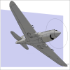
Recommended Posts
Create an account or sign in to comment
You need to be a member in order to leave a comment
Create an account
Sign up for a new account in our community. It's easy!
Register a new accountSign in
Already have an account? Sign in here.
Sign In Now