Search the Community
Showing results for tags 'Scratchbuild'.
-
The Sci fi scratch building machine has been switched on again and It's dialed back to redo an old subject. A year or so ago @Alex Gordon passed on a couple of unwanted Airfix Sailing ships. Victory and Golden Hind. Parts had been painted or put together. It stirred the inkling of an idea. Many thanks again, Alex. Then recently I was given a half built mojo failure 1/144 Revell Flower class model ship by a brother in law. I've always liked the work of artist Ian McQue. I've previously built two anti gravity boats; Misfit 1 & 2 So why not have another go? Links to the previous builds below. https://www.britmodeller.com/forums/index.php?/topic/234963278-misfit-is-done/&do=findComment&comment=1668744 https://www.britmodeller.com/forums/index.php?/topic/235052278-misfit-2-is-finished/&do=findComment&comment=3293519 I've been tinkering with what I've got (Ooer!) for a week or two, trying to configure the superstructure, and I may just have it sorted. The scale will be 1/48th. I've put a figure on board here for clarity. First job was to dissemble the Flower. TET did that. So I made a hole in the bottom and built a card structure to hold the clear plastic pole. The paint is how I got the model. Not my work. I've cobbled together some superstructure. Boxed in a couple of holds and added masts from the Sailing ships. The smokestack is the original. The big black contraption is the thruster unit. It was a large scale motorbike engine part. The yellow parts were ludo counters and the green bits are from a toy. So this lot provides up/down/fore and aft thrust. And the other side. The McQue ships in his drawings don't have thrusters that I can see. but I liked the idea. They also don't have any visible anti gravity generators either. They're probably buried in the hull somewhere. These are just quick shots that I took today. I'll take better ones soon. You can find Ian McQue ship pics on line. What you've seen here may not be the final layout for the deck etc. I'm making this up as I go along! Thanks for looking. Comments and suggestions are always welcome. Cheers, Pete
-
- 4
-

-
- Ian McQue Inspired
- Scratchbuild
- (and 1 more)
-
Stockente. German for Mallard. This is a scratchbuilt mine detector drone for the Maschinen Kreiger universe. Not an official model from Sensei Kow Yokoyama. A couple of years ago the Gas Engineer did the annual service on our hot water boiler in the utility room. We didn't have a Carbon Monoxide detector in there so he stuck one on the wall. Fast forward a couple of years and it started beeping. Low battery? It turns out you can't change the battery, it's hard wired in. Taking it apart did it no good, so the insides got binned. But I kept the case. It could turn into a small scale Spaceship. But that was not to be. In the past @bootneck had sent me a box of unwanted kits. One of which was a drone. The Reaper I think. Hmmm, What to do... Now, does that look like some sort of Duck to you? The floats are ex Airfix Ju52 BTW. Paints by Tamiya. Part of the kreiger universe is set in Australia. North of there are lots of Islands where the water may be mined. I remembered the WW2 Wellington and Ju52 Mine detector Aircraft. Why not use a Drone in the future? I had some 1/48th A-10 Thunderbolt kit parts. Here's the underside of a wing grafted onto a cut down Reaper wing. This happened on both sides and the joint was filled in. The big grey lump is the detector case. So with the A-10 engines stuck on top you get this. With a broad chord wing for good lift. And eventually it ended up as seen here and below. Decals are ex spares box from various sources. I kept the green camouflage fairly subtle. Droptanks fitted. Those engines don't run on fresh air! Lots of yucky algae all over the floats. Super futuristic flexible carbon fibre type supports (bent sprue) between floats and the mine sweeper fairing. A similar shot but with a good view of the engines. The intakes are the caps from kids yoghurt pouches. They were purple. I thought that if the paint was eroded then they could be actual purple printed items. And at the rear I think the tailplanes are ex Gannet. Underneath. The big disc is a mine detector ring. (Probably. This is 800 years in the future) It was a Motorbke brake disc. The other four round things are hover fans. Leftovers salvaged from a real Kreiger kit. They'd use ducted air from the engines. I spliced wheels into the floats for moving this thing around on land. They even rotate. The nozzles are wonky because they swivel to help turn this beastie in flight and on water. And speaking of turning. Helmut uses this Donkey to shift it around on land. Most of it was Lego. And here it is parked up on the Flightline with Helmut checking it over before he cleans off all that slime. I didn't do a WIP this time as i wasn't sure if it would work. You'd only have seen scrap plastic and filler anyway. Many thanks for looking. Your likes and comments are always welcome. Cheers, Pete
- 7 replies
-
- 18
-
-

-
- Ma.k
- Scratchbuild
- (and 1 more)
-
Must be time to start another from the list of Sci fi scratchbuilds that are lined up in my head. Back to the Ma.k universe again for a meld of various plastic bits and pieces. In the foreground is this toy walker, 50p from the car boot sale. The idea was to combine it with a Helicopter fuselage. That would create a thin skin troop carrier. In the end I went in another direction. First I removed the 'shield' on the front and cut down it's supports. Last month @theplasticsurgeon donated an old Revell 1/32nd Lightning for an upcoming Kreiger Falke Scratchbuild. Very many thanks again, Tim. I mostly just need the booms for the Falke, so I had the central pod going spare. Hmmm, what to do? See those guns in the back there? they just might get fitted later. Oh look, a headless chicken (ish) It took a little cutting and shutting to get to this point. Weird, innit? Now the pod is upside down to do this. So, do I make a cockpit in what was the underside? Or go A.I. Robot killer? I think it may well end up A.I. Here I've trimmed the 'wingtips'. They'll be finished off with droptank halves. And I cut a slant in the nose. I do have the original clear nose but want to do something different. That's where it stands (ahem) at the moment. Taped up and balanced on the desk. Further progress depend on chores and the cold in the manshed. We shall see. If anyone can think of a better name than 'headless chicken' I'd be interested. A German word would be best. I want to greebly the legs a bit, make them less toylike. As always, Your comments are very welcome. Cheers for now, Pete
- 42 replies
-
- 16
-

-
-
- Maschinen Kreiger
- 1/35th
- (and 1 more)
-
Hello Peaceniks, In 1952, for reasons we can discuss later, the world driver championships were run to F2 rather than F1 racing standards. The change from F1 to F2 greatly favored the Ferrari team because Ferrari had been concentrating on perfecting lighter-weight cars with smaller engines than were used in F1 races. The result was that the latest Ferrari model, the 500, dominated the competition and allowed Italian driver Alberto Ascari to win the championship. 🏁 To the best of my knowledge the Ferrari 500 has no military application. 🙂 I was one of the early 'sign-ups' to this group build and voted for it in the bunfight, so I feel duty bound to deliver something. 'Delivering' is not something I have excelled at in Britmodeller recently. Currently I have four projects underway on these pages (this is a fifth) and all of them are horribly dormant. The Mirage III and the Xantho are now becoming drawn-out embarrassments of inactivity. Each might be a good candidate for a KUTA group-build. It strikes me that time management is a problem for me with these projects. I always seem to massively underestimate how many hours of work are involved and how many months each of these will take, so I'm going to use this project as a time management exercise. I'm going to: Estimate how long it will take. Record how long it takes by keeping a project diary and itemising the hours spent. Be finished by the end of the group build even if I have to take some embarrassing short-cuts to do it. One of the reasons I have chosen this particular subject is that it is a relatively simple shape, at least for a car, and I have a good set of drawings. The drawings came from the magazine shown below; Scale Models, Nov 1986, Argus Publications. The Vivid Viggen might have to wait for another Scandinavian Group build. Looking at these drawings and assessing the coming project: On the positive side I'm seeing a simple 'fuselage', no wings, no tail, a roomy cockpit with no ejection seat and only a handful of instruments. Blessedly, there is no cockpit canopy! 🙂Compared with many other subjects there are relatively few exterior details. On the negative side I'm seeing spoked wheels and some 'busy' construction around the steering linkages. There are four oddly shaped exhaust pipes leaving the vehicle which then merge into two and then one. There is a large hollow volume between the driver and the firewall and the walls of the cockpit will need to be kept thin to be in scale. Racing cars typically have a near flawless gloss paint finish (which is a potential nightmare) and i think that the numbers will have to be painted on rather than decaled. There is no option to build this with the undercarriage retracted. Overall I'm guessing that about 60 hours work should see this done. Let's see how that estimate works out. I hope some of you will come along for the ride. Bandsaw Steve
- 90 replies
-
- 23
-
-
-
- Scratchbuild
- wood
- (and 1 more)
-
Happy 75 Birthday NATO 🇩🇰 It is probably true to say that there is no organization in the world that I admire more than NATO. I don't want to go into depth why since I might just get a bit 'political' and we cannot have that here, but I am prepared to say that - in my belief- if NATO had not existed for the last 75 years, the world would be a much more dangerous place and many fewer people would enjoy security and freedom.With this in mind I think I have no choice but to take part in this most excellent group build. I really like the idea of the flags! It's unique and intriguing and might just give an incentive to folks to model some of the smaller nations that might sometimes be overlooked. ‘My’ flag is The Netherlands; however, try as I might, I cannot find a Dutch subject that grips me quite as much as a Royal Danish Air Force F-100D! Yes, a Super Sabre complete with grotty, patchy, olive-green, livery! Admit it... you know the kind of filth I mean! Another reason to pick the Danish Air Force is that a friend of mine who collects models lives just 5km outside of Denmark and yet has not a single Danish item in his collection. (In the interests of transparency I should probably point out that I am referring to 'Denmark' the small coastal Western Australian township rather than 'Denmark' the Scandinavian constitutional monarchy - but you get the idea). I really like the F-100! It just looks so damned mean. It has to be the most shark-like looking aircraft ever made and its relatively simple geometry makes it a great subject for scratchbuilding. When I was a teenager I scratchbuilt one in roughly 1/100 scale and it came out OK, but it did not survive the various parental 'junk purges' that punctuated my many years living away from home and now - alas - it's in landfill someplace. Never mind, let's just make another one... a bigger one! Here are my references... some inspiration... and the raw materials! I'm hoping this will be a good chance for me to practice and improve on many of the methods that i used for the first time during my - still ongoing - Mirage IIIO build. This project I'm hoping will be relatively simple. Much of its success or failure will depend on the final painting and weathering as I'm hoping I can make this look like a jet as battered and worn as those in the pictures above. But let's start at the beginning. As usual I have selected Jarrah for the fuselage and have used cheap photographic spray adhesive to stick the relevant plans on the side. Here is the very first cut of the entire project. Shockingly that's not a bandsaw, but don't worry I will be using one very soon. OK - here it is, the first bandsaw cut! Let's call this the moment that the ‘project proper’ begins. To get to this shape does not take long. After some sanding and general tidying up we have this... Which is only the starboard half of the fuselage. I will be cutting out the port side tomorrow night. I have absolutely no hope whatsoever of finishing this project within the allocated four month timespan, especially since this new build must compete with the ongoing Mirage project which must be finished by August 2024. Nevertheless I do think that in the limited time available I can probably bash together sufficient shapes so that it is unmistakably an F-100. Following that I'll just transfer this thread back to the 'main pages' and carry on to the end. In the meantime I hope that this is of interest to you NATO enthusiasts and that you can all get some enjoyment out of watching my humble attempt to turn out a Danish Hun. Go Team NATO! Bandsaw Steve
- 70 replies
-
- 35
-
-
- RDAF
- Scratchbuild
- (and 1 more)
-
Schmetterling - German - Butterfly (Most Kreiger stuff seems to have German names. This seemed to fit) A few months ago I found a toy car in a charity shop. Cost, One Pound. Quite large, with a plastic shell and underneath. the chassis looked like a cheap version of Lego Technic. I think the brand name is Science Museum. The parts join together with small plastic plugs. At the weekend I started to build something I'd had in mind for some time. An Anti gravity lift platform. It would be used for shifting heavy cargo. If you go onto the tube & look up 'Salad Mug' you get a sci fi short film. I think the program they used is Blender? The detail is amazing. One thing in the film was a lifting platform. Light bulb moment! The chassis was something like this. I've altered it somewhat to suit my build. The car had working steering via a rack & pinion set up. More car parts. I've used (sawn up) two examples of the pale grey block with the four plugs on the right here. After picking my parts boxes I ended up with this lot. Some of it will be used. See the white cup shaped items with red interiors? Very old Italeri truck wheel parts. They will be used. A rough mock up of the general idea. The front to the right. The tall bit on the other end is the operators cabin. The load bed is another old toy. You plugged letters into it to learn spelling. It's very fragile clear plastic. Yes, that's Helmut in the 'Cabin'. The balls are from a long abandoned kids game. Side rails are 'almost Lego' parts. I won't be using that 'Cabin'. it's a Motor bike bit I think. I'll make another similar one. At the rear of the load bed we have this lot. Yep, A 1/76th Panther engine deck. Glued to something you'd plug into a TV. The two round ribbed things would be coolant containers. probably. It's mostly just a mock up for now though. Landing gear. Heavy duty. Some kids large toys come in cutaway display boxes. You need to unscrew fixings to remove them. I have three of these fixing things leftover from the Christmas Morning frenzy. The pale yellow stripes are coffee stirrers superglued and filed to shape to fill a slot in the sides I put small pale yellw greeblies on the feet to fancy them up a bit. So, Italeri truck wheel part. A bit of tube and a split pin. WTH? The pale grey blocks with four plugs were cut up. Holes were drilled, Tank wheels glued on and all was glued to the balls. Insert cut down split pins with a bit of white tube on the sharp end for decoration. And then I can just plug them into holes in the chassis frame. And remove them for painting too. And here we have the front end with Helmut showing how close to the ground it is to facilitate (ooh!) easy loading. It has two gear struts at the rear and one here at the front. There seems to be a bit of a tilt here. Tut! The blue bit (a grey one is for the back) is what you use to even up your double glazing window units. A slightly better shot. Helmut looks pleased. And that's the main thing. That's as far as it's going for a few days now as it's midweek Grand Daughter sitting time. Back to the bench later this week. Thanks for looking. Comments, questions and ideas are always welcome. Cheers, Pete
- 38 replies
-
- 14
-
-
-
- Machinen kreiger
- 1/20th
- (and 1 more)
-
Happy Anniversary Skylab 50 years ago today Skylab, America's first space station, was launched. I'm not going to discuss Skylab's history in detail right now, there will time for that later but suffice to say that this programme set numerous records for human occupancy in outer space, gathered an enormous amount of scientific data regarding both planet Earth and the Sun and was involved in a couple of episodes of aerospace drama that sometimes tested NASA’s ingenuity and determination to the limit. It was also - in its own way - rather beautiful. Skylab is well remembered here in Western Australia because on the evening of 11 July 1979 as it disintegrated in the Earth's upper atmosphere it scatteried debris over a large elliptical area to the North-East of the small W.A. town of Esperance. No one was hurt and no damage was caused. For a brief period the eyes of the world were on Western Australia and a flurry of activity followed as numerous folks went out in search of souvenirs. Surprisingly I have only ever seen one model of Skylab in W.A. It was given to the Shire of Esperance by NASA and is on display, along with various pieces of debris, in the Esperance community museum. I'm going to have a crack at building my own model and hopefully - despite this early start - will be able to join into @bianfuxia's upcoming 'Beyond the Karman Line' group build. Here are my main references. And the principal drawings that I will be working from. It turns out that 70mm PVC piping from Bunnings is freakishly - exactly - the correct diameter for the main orbital workshop. and that 25mm electrical conduit is also - exactly - the correct diameter for the multiple docking adaptor module. So, earlier tonight, on the evening of the 50th anniversary of the launch, I made the first cut in this project. Followed by marking up and cutting out two bulkheads from MDF. That sit snugly in the workshop like so... and then have a central hole cut in them so that the central 'axis' of the model (the aforementioned conduit) can slip through the centre of the orbital workshop . Leaving this... Which is a pretty good start I think. Unfortunately I now have four projects on the go, which is not ideal. Top priority stays with finishing the PZH-2000. I'm giving myself plenty of time for this one - about 6 years in fact - as I want it finished in time for the re-entry anniversary! 🙂 Best Regards, Bandsaw Steve
- 52 replies
-
- 24
-
-
- NASA
- Scratchbuild
- (and 1 more)
-
Some time ago I scratchbuilt an Ma,k Falke. I wanted to make it a high altitude version so it got a pale blue colour scheme. I then went further with that and added squadron markings etc so that it resembled a Le Mans Porsche 917 from the seventies. Recently I noticed a slight up cock, I'd made the cabin entry hatch too small. It had to be changed. Brave pills helped me to attack it with a cutting disc in the Dremel. I made a new Cabin from the clear parts of a 1/24th Revell BMW Mini and a new hatch from a plastic spoon. As per Ma.K lore. There's a strip of plastic covered wire around the join. A step and a sensor plate on the side with extra armour on the front. This paint is a homebrew of red oxide Tamiya acrylic. Then today I whipped up some more pale blue and it all finally came together. In the cockpit is Rolf. He's just been adjusting the dwell angle on the Dynasticrator gauge with his favourite red screwdriver. Now he's moaning at Helmut about how long it took. Tsk! Rolf is from a Tamiya1/20th pit crew set. His body needed some alterations to get the right pose. I'm rubbish at figures 😄 On the left side I've fitted the big scoop as per the original kits. The sensor plates are Nato black. Weathering is on the heavy side but that's what I wanted. At the back I've added this vent. It just seemed to be right at home there. The non slip mats are fine mesh glued into place. Close up on Rolf and his screwdriver. The extra armour plate on the front is just card with Meng nuts and bolts. Here's the original cabin that I cut off along with the spoon I've used in the rebuild. The next project is in planning and will start soon. More Ma.k. Many thanks for looking and your comments are always welcome. Here's a link to the WIP
- 4 replies
-
- 18
-
-
- Maschinen Kreiger
- 1/20th
- (and 1 more)
-
Some time ago I scratchbuilt a Maschinen kreiger Falke in Gulf racing colours. One day a few months ago I realised that I'd made the hatch too small. It was more suited to 1/35th. Doh! What to do? Leave it as is, or hack it about and change it. After two bottles of brave pills I revved up the cutting disc... As it was. Helmut in attendance to give it scale. It's obvious (now) that he would struggle to get in there. And, after the attack of the flying discs. The white oval is the new hatch. Cut from a plastic spoon as per the original models. And this is what I'm using for the cockpit. A 1/24th Revell Mini gave up it's clear parts And I cut some card. It can be seen here that the hump alongside the cockpit is separate from it. They should be joined. So lots of filler and sanding joined them up. Also seen here, how to do the cockpit insulation blankets. Seals from canned instant coffee. Nicely textured they cut easily and stick down with superglue. I added more detail in the cockpit. levers and wiring etc, At the front a big black screen would display the outside for the pilot. And from the other side. With the top on, even with the hatch open, you can't see a lot in there but it was fun to do. Not a weird Oyster. It's the inside of the hatch. The green thing is part of the opening system. Et Voila! As they say in foreign parts. Not glued down yet. Still a work in progress. Helmut poses yet again. I've added steps, handrail and non slip patches . This is as it stands this afternoon. Matching the paint is going to be a challenge as I'd just mixed it up back then. Thanks for looking. Comments are always welcome.
- 5 replies
-
- 14
-
-
- M.a. k
- Scratchbuild
- (and 1 more)
-
Here’s my take on a Napoleonic 2nd Hussar veteran, posing for his studio photo. I found a whole series of photographs of grand old French veterans that are full of character, squeezed into their old uniforms. I chose this chap as my first stab at them, and scratchbuilt/sculpted the lot using Fimo, greentuff, milliput and a load of thread, wire and foil. It was a great project to do and I’m looking forward to tackling others in the collection. I took a bit of a liberty and modelled the back of his jacket as having had a last-minute, poorly executed and hurried alteration to enable his middle-age spread to be accommodated. Having finished him and after studying the original (black and white of course) photos, I’m now not entirely convinced this chap is actually a 2nd Hussar – his jacket braiding appears dark in the photo, so it could well be that he should be sporting a different colour scheme, but no matter. and here's the original photo, plus an internet-sourced fantasy colour scheme.....
-
 Hi All, Here we are following on from the 1/32 Malta Gladiator by far my best build so far. With the next build, I've decided to do something more challenging, creating an almost extinct inter-war torpedo bomber in a scale never seen before... I give you the 1/32 Vickers Vildebeest, this aircraft was a design that first flew in the late 20s and managed to cling on until the early parts of WW2. It's a all metal structure bi-plane covered in fabric and from a CAD design point of view a head-scratcher... as very little info remained from that period hardly any drawings survived and only two fuselages both in NZ survived one Vildebeest and one Vincent. so I started designing the fuselage around 2 years ago mucking about with line drawings off Google and managed to get a basic representation of the shape i have now improved this into something I'm happy with, 3d printed resin is great for detail but can warp, it is very fin so that has been something i have had to design around. after already printing my original fuselage and not being happy with the results I redesigned the fuselage and got a 1/72 special hobby kit for reference and to check scales which to my surprize were pretty good!! this image shows the scale of the vildebeest very large for a single-engined aircraft CAD Model of the RH fuselage size prior to being sectioned for printing. Here are the prints of both halfs ready to have supports removed and assembled. first mockup with the engine (Bristol pegasus from Vector resin). First print of the floor. A lot of work is required yet I'm currently trying to get the interior and cockpit complete and fuselage glued before the exterior gets a lot of attention. The fuselage frame is constructed from styrene rod with 3d printed fixings. Some of my hall from Telford included airscale PE and decals which should make it all come together. small prints such as levers and bellcranks are visible from the side windows so I have modelled them this print wasn't perfect but the parts were useable. thanks to a generous member of my local model club (Thanks Simon) for lending me some images and info he had for this aircraft one of the most valuable items was a rare instrument panel drawing which I have modelled will be improved with the airscale goodies, the extra bit at the top is due to the different profile of my fuselage but this should be hidden once the model is complete. If anyone has any questions I'm always willing to try and answer them the best I can. Thanks James
 -
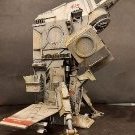
Yet another small scale freighter scratchbuild for my wall display. No WIP but I will post an in progress pic here. If you think about it, How many people are on a Star Destroyer? The logistics of feeding and caring for them all. Plus keeping the ship going with spares, lubricants, replacement people etc would be horrendous. Plus, Just where is it at present in the Galaxy? So you'd need a stream of support vessels. Hence these little jobbies that I keep bashing together. Or am I overthinking this? Goodness knows what the scale is. Probably lots of zeroes. The basic hull was a 1/48th Hawk with 1/72nd Mig 15 fuselage halves each side. Then add drop tank halves etc. As for the colour scheme, I wanted to go a bit Chris Foss. (Hence the name) I used to love his seventies Sci Fi pictures. Last week I added some greeblies to the display. Just random bits from the spares boxes. Hopefully they add interest. \the solar panels are made from 1/48th Huey Cobra rotor blades. Here it is naked! The Hawk fuselage is upside down and pointing to the right. Closeup of the MIG fuselage half. Not sure what the fins are from, but they hint that this ship is atmosphere capable. The belly of the beast. The grotty/very worn paintjob was a bit of an accident. I thinned the Acrylic too much! Now the rotor blade roots become obvious. The build took place over about three weeks, whenever I had time. Thanks for looking. Your comments and questions are always welcome. Cheers, Pete
-
 SS Xantho, Western Australia's First Steamship. St George's Terrace is the main business thoroughfare of Perth and every 20 metres or so along its length, embedded in the footpath is a plaque similar to the one shown below. Each plaque commemorates a year in the history of Western Australia and the most eminent person in the state that year. There are some names you may have heard of; Allan Bond, Dennis Lillee and Bob Hawke for example - I note that Rolf Harris's one has recently disappeared!? But most of the names are those of administrators, academics or business people whose stories are now forgotten by all except their decedents or the most ardent of local history buffs. In the course of my years of work in this city I must have walked past this rather battered looking plaque hundreds - probably thousands - of times without noticing it or giving it a moment's thought. 1870 - Charles Edward Broadhurst - Pearler... About two year's ago, on a lunch break, I dropped into my favourite bookshop and while perusing the local history section found this recently published book. The nautical cover caught my attention. I wondered if there would be schematic drawings inside. I'm always looking for schematic drawings. There were a few sketches in the book, but none of the four-view technical profiles and cross-sections I was hoping for. There was however this artist's impression of a most fetching looking 19th century steamship; The SS Xantho. I started to read and once I started into her story - and that of her owner Mr Broadhurst - I could not stop. It turns out that this vessel - and a rather extraordinary vessel she was in certain regards - was Western Australia's first ever steamship. I'm not going to try to tell her history to you right now, because that would make for a very long introductory post and I am anticipating that this project could last for some time. We can discuss her history in detail later. Suffice to say that this ship sank in November 1872 at Port Gregory, a tiny, tiny settlement 500 km North of the state capital Perth. (See the map below.) Fortunately no lives were lost. Following her loss she was essentially forgotten and sat undisturbed for more than 100 years and was of no apparent significance beyond being a hazard to navigation. The red arrow shows the position of her wreck, right at the entrance to the harbour and the yellow arrow the site of the only jetty for scores of nautical miles in any direction. But in 1983 Xantho was re-discovered by staff of the Western Australian Maritime museum and, due to a number of extraordinary and completely unforeseen factors she was about to be propelled to global fame - at least within the world's maritime archeology community. In the words of Dr 'Mac' MacCarthy, the world's leading expert on Xantho - 'This ship is world famous - in certain circles'. I think it's a shame so few other people have heard of her. Once the Avro 504 is finished I'm going to build a model! Be warned though Britmodeller maritime folks I have great plans for this one, and I'm going to need all the help and expertise that I can get, because this promises to be a research nightmare! Very Best Regards, Bandsaw Steve.
- 396 replies
-
- 20
-
-
Hi, Not quite 3D, but there is some overlap in the principles used. Does anybody know of a good tutorial to design PE? I can find my way around in Fusion and Gimp. Can sheetmetal in Fusion produce files for etching, or does that still require 'hand' drawing? I was thinking that Sheetmetal would help with virtually folding parts to check viability for example.
-
 After completing my scratch SS Servia a few months ago I thought I’d happily return to an aviation subject for my next project but unfortunately the nautical bug seems to have bitten quite hard so it looks like it will be another ship project after all ! Initially I was looking at building an early RN destroyer in 1/72 (HMS Jason caught my eye as did the Acorn and early tribal classes). Being based in SE London the obvious starting point was a trip to the Greenwich archives which I did in May. I could blather on about the visit for ages, suffice to say that unrolling sets of original plans from the late 19th century is a superb experience. Anyway a change in personal circumstances means that for the next year or so I will be based in Exmoor with a reduced workspace so something of that size wasn’t going to be feasible. I then stumbled across the Seaforth title on RN Trawlers and Drifters and finally decided on a Round Table class minesweeper (its on the cover). The book includes many sets of useful plans but they are quite small, Cornwall Models can supply sets of the MMI plans at 1/96th so that settled it. The finished model will be just over 1foot in length so a much better fit in my temporary mini workshop. The plan was to use primarily wood and metal in this project instead of plastic but again because of space and limited tools I opted for plastic. Step #1 was to cut out the hull cross sections and profile from 1.5mm plastic sheet. I don’t own a power fret saw so I opted to create each cross section as 2 halves clamping each pair together so that they can be sanded to be identical in shape. For the prow I made a brass insert to ensure a crisp line and filleted this into the profile. The shear lines in the plans do not extend aft of the propeller so all I had to go on for the shape of the stern section was a plan view and profile. I built the shape up with various addition cross sections that were sanded back until I had a shape that I was happy with. The sections between these were filled with balsa to provide a solid base for the plastic skin. Once this was done I made a simple jig to hold the spine straight whilst the planking is done. My approach on this is to use quite thin plastic sheet (0.5mm) and to then build up the hull from the inside with more plastic and resin. The smoothing process means that the original planking is almost completely sanded away in places. I used some auto filler to get a nice smooth finish and then set about the transom which extends all the way around the sides up to the fore deck. This is quite a fiddly job as it splays out at the stern rather than being vertical. I started by using printer paper taped in place to get a rough shape and then gradually refined this eventually moving to card and ultimately plastic sheet. The shape is too complex to do in a single piece so I made the stern section and then butt jointed the side sections to this. More auto filler, more sanding and this is where it stands currently. The next step will be the hull plating, the plans do not include a shell expansion but there is a set in the book for another class and I’ll use these to create something that is hopefully reasonably credible.
- 209 replies
-
- 18
-
-
- Scratchbuild
- Minesweeper
- (and 1 more)
-
Happy Birthday Royal Australian Air Force Today is the 100th Anniversary of the formation of the Royal Australian Air Force. I am not going to write much about the history the of the RAAF because I am no expert. Suffice to say that on this day 100 years ago this service was formed as an independent air-arm and it has strong claim to be the second such service formed anywhere in the world. It has been a cornerstone of Australia's security and this region's stability ever since. The RAAF played an active and effective role in the Second World War as well as numerous 'smaller' but still very significant conflicts, including Korea, Vietnam, the two Gulf Wars and Afghanistan. It has assisted in many peacekeeping and security operations around the globe and has played an important humanitarian role in innumerable civil defence emergencies. At one stage, immediately after World War Two, the RAAF gave Australia the fourth largest national air arm (by number of operational aircraft) in the world. We Australians, and our various allies should be most grateful for the service that the RAAF has provided over the last century. Three years ago I started my build of an Avro 504 to mark the occasion of the formation of the Royal Air Force. Now, it would seem wrong of me not to do something similar for the Air Force of my adoptive homeland. I've been planning for this for a while and was hoping to have at least one of my three other threads on Britmodeller closed by now, but that has not happened. Time waits for no-one and if I'm going to do this to mark the anniversary then I have to start today; ready or not. If we are going to 'do' the RAAF - let's pick a good subject. Let's look at something fast... perhaps even supersonic. Hmmmm... how about a swing-wing thing...? 🤔 Nice idea! But do you know how big one of those things is in 1/32 scale? My display cabinet is only so large. What about something American with a big droopy nose, two big burner cans tucked in under a single swept back tail and tailplanes set an an outrageous angle of anhedral..... 😀 Again, Nice! But that's a very complex shape and I want to finish this before the next 100 years passes. What about something French and triangular that I once saw when I was a lad at an airshow at RNZAF Wigram... Yes! Now we are talking... Let's do one of these! If you have seen my work before you know what comes next. Get a bunch of drawings together - in this case downloaded as PDF's from the internet - and get them printed to an exact 1/32 scale. In this case there are three 'master' sheets. Get one of each laminated and half a dozen copies of each printed out. Just use everyday copying paper, no need for anything special. Don't worry about the radar under the chin folks - I know that's not an RAAF thing. Here is the compulsory 'sprue shot after opening the box' photo. A fair bit of plywood will be used but most of the parts are jarrah, the same stuff I used on the Avro 504. Jarrah is grown right here in Western Australia, is beautiful to carve and strong as anything. This will be important since there's a good chance this thing will have gear down and once the forward undercarriage bay is cut and the cockpit hollowed out there will be very little remaining intact wood to hold the nose in place. Now we do some dry fitting. Yep - the major fuselage pieces fit together without any gap at all. Note also how there's no ejector pin marks or other blemishes. Tamiya quality fit - although lacking some detail at this point. 🧐 Now I sat down and had a think. How was I actually going to make this thing? Carve the fuselage out of a single block? Or break it into multiple more manageable components. Overall this shape is a bit more complex than, say the Mig-15 that I built in 2016, and requires a bit more thought. Once some decisions are made we can start marking out the cuts. This is the first cut line marked up for the entire project. This is the moment I consider that work actually began - 8.02 PM 31 March 2021 (WA time)...100 years to the day. 👍 Like I say - initially there's a bit of planning and marking up required. Some of the decisions might be a bit counterintuitive, but I've learned a lot over the course of my last few projects and I think there's method in my madness. Who knows though, maybe there's just madness in my method? I've decided that there will be a separate central 'fuselage and cockpit' section cut out that will nestle between the air intakes and the rest of the fuselage assembly. This component is defined at this point by the red ink. Somehow the wing will also need to be accommodated, but for now it's one thing at a time. Now grab two lumps of wood and cut them longer than the section just marked out. One thing I have learned is that surplus wood is not generally a problem - insufficient wood is. Hold the two pieces of wood in a vice and drill a series of holes (four in this case two on either side) clear of the planned cut area. Drill each hole about 3/4 of the way through the entire thickness. I guess it's harmless to go all the way through but this time I chose not to. Now slip a dowel into each of the holes and cut off the surplus. In this case the dowel fitted into the holes perfectly so no glue was required at all! This is a bonus because, although I want these two bits of wood to stick together and stay nicely aligned, fairly soon I'm going to need to pull them apart splitting the fuselage in two again in preparation for hollowing out the cockpit and UC bay. Now cut out the paper plans and spray some cheap photo adhesive onto one side of the prepared wooden block. (No photos this time sorry, I forgot). Cut out the pattern with the bandsaw. It was now getting late at night and this was after Mrs Bandsaw's 'powertool noise curfew' so I left a full 5mm clear from the pattern and just raced through the cut as quickly as possible to get the noisy bit over and done with. This is the birthday of the RAAF, so noise curfew or not, there has to bandsaw action! This is the result so far. There's a long way to go... I hope that some of you come along for the ride. Per ardua ad astra Bandsaw Steve
- 514 replies
-
- 51
-

-
-
- RAAF
- Scratchbuild
- (and 1 more)
-
I love the Renault FT and I have two in 1/72 scale in my collection, however as you can see they are about the size of a postage stamp. So doing the various calculations 1/24 gives me an 8.2 inch long model so a nice size. This is going to be a slow off project build and I’m intending to build it with all the hatches open. So next step scale some plans up and start cutting styrene
-
Once again I'm delving into the depths of the future to suit my weird modelling purposes. During WW2 the RAF had the 'Tilly'. Short for Utility vehicle. Mostly built by Austin, they were a small multi purpose pickup or Ute. Why wouldn't they have a similar vehicle in the kreiger universe? No, Not an Austin. But ideal for my porpoises. From King Kits Salvage yard, part started, for about 7 quid. Painted Humbrol Brass (The tin was in the box) and missing some trivial bits. It was meant to be motorised. I needed a modified floorpan and found this red one. Out with the razor saw. Lots of chopping and changing later I had this bodged up rear axle on airbags (Actually large rubber grommets, Perfick! Much measuring and trepidation later I had this. The brown oblong will be the bed. It's actually a 1/35th truck part. Some 'good enough' 1/35th Truck wheels and chunky tyres added for that Military look. And here's the hole. I've since made a cab rear and now the bed almost fits too. There will be sides and a tailgate. The body has been sanded rather than stripped. (A) I didn't have the chemicals, and (B) A rough Military finish should suit. I'm going for the' unknown possibly electric motor under the Bonnet' idea here. No need for technical bits. It's only going to sit on display in the manshed with the Falkes anyway. But I want it to look half decent at least At the moment (After fixing the shed roof over the past two days) I'm sorting out the truckbed and will need to make internal wheelarches. Any ideas, suggestions, likes, loves and whatever else @Mike may have added recently are always welcome. Bring your own biscuits or Cookies and a tea bag. Her indoors bought us a new kettle. A cup or mug could be a good idea too. Many thanks for looking, Pete
- 36 replies
-
- 19
-
-
-
- Maschinen Kreiger
- 1/20
- (and 1 more)
-
Here's another spares box build. I knocked this one up on the quiet without an in progress thread, The idea is it's Star Wars ship from the Aratti system (It's a big galaxy they have) used to escort commerce ships. I had a 1/48th Cobra and a Mil Hind in 1/72nd. Other parts came from the bits boxes as and when required. It's an odd looking thing I must admit. The Pilot gets a full on frontal view at least. Guns are under the chin. The tail came from a WW2 German whiff. I wanted a slightly alien design look. I think I got there. The underside, obviously. Engines are two 1/48 Mosquito nacelles. And there he is. I sprayed gloss white on it and did lots of weathering and big paint chips. The round object at the front top is the Nav droid. Slotted in behind the cockpit, like on an X wing. One of the in progress pics that I took. And a pre-primer shot. Pre-primer again. The droid was a large yellow light. The round bits at the engine rears were clothes hanger size rings. There are bits of masking tape on the droid here. And the basic airframe so you can see the main parts. Thanks for looking. Your comments are always welcome. Cheers, Pete
- 7 replies
-
- 18
-
-
- Star wars
- Scratchbuild
- (and 1 more)
-
My workshop has temporarily limited operational capabilities: the paint shop is closed due to numerous equipment failures. I wrote a letter to Santa Claus, demonstrating beyond any doubt that I had been good all year long and deserved a brand new, shiny airbrush. My wife promised to deliver the letter to the addressee. Therefore, there is reason to believe that one of the hardware problems will be solved in the last days of December 😉. There is still the issue of compressor repair, which unfortunately is going worse. Anyway, I can't paint old things for now, so I started building new ones. A construction mech has been on my mind for a long time: an excavator or some sort of demolition machine from the near future, with legs instead of tracks. The thing is supposed to be in the mecha style: a robot with an operator inside. I'm not sure that mecha doesn't only apply to armed vehicles, but I don't feel like making another military thing. Make walls, not war 😉. Construction started about two weeks ago. This is the operator's cab "kit": plastic cosmetic jar and acrylic Christmas bauble. I have several such baubles. This is a semi-finished product for making your own decorations. It used to be perfectly transparent, but I dulled it with sandpaper. For now, I only want to use half of the bauble. I glued the HIPS floor inside. This can be seen, although somewhat blurred, in the photo below. Several rings of different shapes will form the control panel around the operator's seat. On the lower right is the front cockpit panel. I glued this to a piece of a photo etched part that used to be the tank's mud guard. The operator's seat is carved from 3mm thick HIPS. First steps to building the leg drive module. And the first steps in building the legs. I decided to connect the operator's cab and the drive module with neodymium magnets. On the one hand, it will facilitate further construction and painting, on the other: the cabin will be able to be rotated around its axis. From my experience, glue is not enough to properly attach the magnet. The most durable method is to attach it using Milliput, preferably in such a way that both magnets are separated by the plastic to which they are attached. This is what the cabin module, connected to the drive module, looks like at this stage. The jar made from polyethylene was sanded and covered with a HIPS strip. I want to avoid a mishap as when building a spaceship for Above Karman Line GB. There, I skipped the step of covering the polyethylene with polystyrene and ended up with peeling paint. Thanks for watching. Wiesiek.
-
Hi folks…! I’ve been distracting myself with a series of kits – interwar stuff, 1/72, and even an hairyplane so it’s now high time for another armour scratchbuild. I’ve decided on something a bit different (although it’s still covered in rivets) and have plumped for a WW2 tankette. I saw Bovington's one recently and was charmed by it. The wealth of funky paint schemes is also a great incentive. It’s tiny, so I’ve made my mind up to jump to 1/16 scale for a fresh set of challenges. Unusually for my projects, there’s quite a lot of reference stuff online, including plenty of drawings, so I loaded one into CAD and modelled up the main panels. I then flattened these into 2D and added some details, ready for printing out and cutting the parts from 0.75mm plastic card. Despite working in CAD for over thirty years, I continue to resist the lure of 3D printing, so it’ll be a build of plastic card and nail caviar as usual. That said, I’ve no real idea how to tackle the tracks as yet – maybe I might dip my toe in the printing world after all…. I’d also like to do a figure for this but I’m not sure that an internet search for “1/16 Italian tankette driver” will pull up many results, so he might end up being another scratchbuilt element of the project. Wish me luck!
-
 I'm back with another adventure, a 1:48th scale model of the first ever destroyer in the Royal Navy, HMS Havock of 1983 Following the trials of HMS Lightning (torpedo boat No 1) navies around the world began constructing torpedo boats to launch the new Whitehead torpedoes. To counter the threat of these torpedo boats torpedo boat destroyers were commissioned, capable of fast speed (for the time) and with guns capable of eliminating the threat. This is nicely summaried in this video for those interested Yarrow and Thornycrofts were the first builders to enter the race to build the first TBD's with Yarrow launching the first of the new A class 27 knotter's, HMS Havock in 1893 The A class vessels were all different, some having bow torpedo tubes, some not, with varying boiler arrangements (that technology was changing very fast in the 1890's) and differing level of equipment and guns. HMS Havock was one of the early smaller vessels being 180 ft between perpendiculars and 185 ft overall length, displacing 275 tons fully loaded. She had 3 torpedo tubes and 1 12pdr 12 cwt QF plus 3 6pdr Hotchkiss QF deck guns Here she is as originally fitted with locomotive boilers And the builders model I've already posted, also @1:48th scale So, its a big model, 46.25 inch long but very narrow and not too tall. It will make a nice comparison to HMS Medea, the black painted M class destroyer I built 20 years ago. After my loft room sort-out, I now have the space to display it, so here goes.... As ever, I will be building the hull in wood plank on frame with aluminium plating and brass fittings. Where ever possible, wood for wood and metal for metal While the dolls house is developing, I will be working on the drawings and have enough information gathered now to start the thread, though it may be slow to begin with. The key decision to start recording the build came on Friday with a copy of the as-fitted drawing from the Maritime Museum archive. I'm not allowed to post it here but Lyon's great book on early destroyers has a copy and this is a scan This scan does not do the plan any justice, here is a sneak of a piece of the full 84mb file For those of you how have not had the opportunity to work from builders drawings, you are missing a great pleasure. Victorian builders drawings (in particular as-fitted ones) are a delight, they took the trouble to draw more or less everything, the drawing even lists the small arms carried in the captains locker... No model plan comes close To supplement this wonderful plan, here are a few other references I have to help me along the way So, the journey begins, more soon Cheers Steve
 -
Time for another scratchbuild. Most de Havilland aficionados would be familiar with the DH104 Dove and DH114 Heron. Quoting Geoff Goodall: "At the end of World War Two, the Australian associate of the parent De Havilland company, De Havilland Aircraft Pty Ltd at Sydney NSW (referred to as DHA) was completing wartime RAAF Mosquito orders and looking for a new design to build for the post-war civil market. The general concept was a single-pilot utility transport for 8 passengers as a replacement for the many DH.84 Dragon biplanes in use in Australia. It was to be of simple rugged construction with fixed undercarriage suitable for Outback operations on rough airstrips, with low-powered 145hp DH Gipsy Major 10 Mk.2 engines, which were in plentiful supply. The new aircraft was the DHA-3 Drover....." (source: https://www.goodall.com.au/australian-aviation/drover/drover.htm for much much more....) Below is a photo (credit: Geoff Goodall) - which bears more than a passing similarity to the Dove, and is of a similar size - but with an extra engine. Actually the Drover had very little in common with the Dove other than stressed skin construction concept. Much more on this at the URL provided above... From a modelling perspective - whilst the Dove has been well served (certainly of late) in 1/72 - the Drover less so. There's a number of modelling articles where people have converted a Dove to a Drover, and older articles converting the Airfix Heron to a Drover (and the Airfix Heron to a Dove) - basically major cut and shut surgery. But I wanted a 1/48 model (my preferred scale) and so we turn to scratchbuilding. First problem was getting decent plans - the best I could find was some 'thumbnail plans' - not sure of source but might well be Jane's or similar. These don't respond well to enlargement (the pen lines scale out at about 6" thick), and there were aspects of these drawings just didn't look 'right'. I know Air Britain has a publication on the Drover with drawings from Juanita Franzi which are sure to be great - but it'll take me a while to source that locally (or pay o/s postage!!), and there's a model to be started! Luckily there's a number of airframes in Australia - including a mostly complete Drover, and a fuselage at Queensland Air Museum in Caloundra. So it was a museum visit, and out with a camera, tape measure, pen and paper. The scribblings below was the result of the visit - the drawing at left the enlarged thumbnail plans I was starting with.. Anyway - after translating all this lot to 1/48 - here's what the fuselage plan looks like - top view, side view and cross sections. This was my main concern with the thumbnail plans and there's certainly some differences... So - let's cut some plastic! The fuselage has compound curves all over the place - which is going to require vacforming. And vacforming means I need a 'buck' of the fuselage. My technique here is to first build up a skeleton of side view, top view and cross sections - which we'll later fill in with 'car bog'. You'll see this happen over subsequent posts. Below is the skeleton being built up. I've cut the side view as a single piece (0.75mm styrene) and am adding the cross-sections out of 0.5mm styrene - half on the port side, the other half on the starboard side - with a 0.75mm sliver removed to allow for thickness of the side view piece.... Little triangles of styrene help provide structure and keep things at right angles. And here's what it looks like with all the pieces of the skeleton in place. It'll need some time to dry before I fill it in. So let's move to the flying surfaces - a few hours work required to get the component parts as you see them below. - wing top surfaces (0.75mm styrene), bottom surfaces (1.0mm styrene) and the empennage pieces (all 0.75mm styrene). - All the trailing edges have had their inner surfaces sanded to a fine taper with wet & dry sandpaper. - I've also built up a tapered spar (basically an I-beam), and a tapered leading edge (laminated 1.5mm styrene) And in about 15 minutes - all the trailing edges are glued and clamped. Main spar is tacked in place, and temporary spars have been used for empennage. This now needs time to properly dry as the process of glueing the leading edge is going to put a bit of stress on this glue joint (done it before - it works fine). That'll do for the first post. Next steps. - start backfilling the vacform buck with car bog. - glue the leading edges of the flying surfaces.
- 123 replies
-
- 29
-
-
- Drover
- Scratchbuild
- (and 1 more)
-
This is a Maschinen Krieger scratchbuild of the Falke Anti gravity fighter, My third in this scale. The 9LM designation is because the basic centre piece is a Jaguar 9LM racing car. The Booms are from a 1/32nd P-38 Lightning. Lots of pictures, so lets get on with it Helmut came a long to help and show some sense of the size of this beastie. I forgot to remove the red masking tape here. Doh! The gun is a converted toy plus add ons. Loads of stickers! Took me nearly all morning. There are lots of ex Phantom warning labels but they don't show up well here. U.S. Marine Corp pilots wear Camouflaged Bone domes, so this guy does too. The rubber seal for the lid is thin black plastic card. The engine is part 1/32nd Me262 and plenty of greeblies with some copper wire. The cockpit lid is part of a plastic spoon BTW. Filler, greeblies and plastic card in abundance on this build. Underneath, three dark sea grey anti gravity units (Table tennis balls!) and a plethora of spares box greeblies. The mucky end. Even bits of motorbike engine and Jaguar cam covers under here. Hellmut again. The footstep next to him is a bit chunky, but it is ex large scale motorbike. Thanks Alex. Not the normal Falke intakes but I think they work here. Another view of the engine. Fuselage paints were Tamiya Acrylic and ancient Humbrol enamel. Weathering by Acrylic pastels. The 'flappy things' on the original Falke were made from 1/32nd Dauntless flaps. Here I used Stealth Bomber Bomb bay doors. A close up of the gun systems. I'd removed the red masking tape by this stage of the photo session! It's big, blue and mean, with it! The black and yellow stripes go with the wasp cartoon on the main body. I'd meant to do them as on Operation Musketeer. Suez 1956. But my memory got the order wrong. They should be yellow, black, yellow. black, yellow. Doh! Looks like I forgot to add the glass in the searchlight underneath too. Tut! That's what you get for hurrying. Here's a link to the WIP Many thanks for looking and your comments are always welcome. Cheers, Pete
- 10 replies
-
- 18
-
-
Here we go again. Are you sitting comfortably? back in October at the Lincoln model show, I was taking a slow march around the tables in the company of @general melchett. Under one of the tables I spied a Revell Rotodyne box, the reissue one, up for a tenner. I'd wanted one for some time, so... Of course this won't be built as intended. But then you knew that didn't you? In one of the Star Wars films a sort of flying bus lands and out steps Ewan Mc Gregor. Hmmm A couple of years ago at the car boot I picked up a display type pod racer for a quid. Hmmm The disassembled pod racer. I've wanted to use the engines on something since I bought it. But, I thought they may not be space going engines, hence the pod racer use. All I needed was a suitable fuselage... How to disguise the fuselage source? Well, I had this 1/32nd P-38 nose piece.. So I sawed off the Rotodyne nose. A bit. The nose cone was slightly too narrow, so I sanded down the fuselage halves at the front to fit. But it was then under strain. So it also got sawn behind the door and card inserted . Much better. You can see here the start of trial fitting fairings, The main rotor fairing had to go, of course. These two black bits are ex SR-71. This will not be a bus, but a fast planet bound freighter. Sort of a much much faster DAF 7 1/2 tonner. Here I'm starting to fill in the windows. There's a 1mm card backing plate glued inside them. Filler has since been used. The card inserts seen here save filler and mean that when sanded I should get a fairly smooth finish. The rivets are going too! The fuselage half locating pins were hopeless. I've added card tabs like on a vacform for strength. And, just to prove that I do like the Aircraft. This hangs in the manshed. Rescued from a Calendar almost 40 years ago! The original is signed Hardy and dated 1984. A lovely picture IMHO. Obviously more is to come. I hope you were able to follow my ramblings and will return sometime soon. If only to try and make more sense of what I'm trying to do here. Given the weather, there could be an outdoor bar by then. Who ordered the cheeseburgers from the barbie? Comments and a more exotic cheese in the burgers are always welcome. Cheers, Pete
- 33 replies
-
- 23
-
-
- Star wars
- Scratchbuild
- (and 1 more)