Search the Community
Showing results for tags 'North American'.
-
 P-51B/C Mustang 3D Printed Upgrade Sets (for Eduard) 1:48 Eduard Brassin We reviewed the new 1:48 P-51B/C Mustang here recently, and as is the way, Eduard have created plenty of after market sets to further improve the detail of your new purchase, and this tranche are all 3D Printed under the Brassin branding. The larger sets arrive in a shallow Brassin cardboard box, with the resin parts safely cocooned in bags, and the instructions folded around acting as padding, while the smaller sets arrive in a flat resealable package similar to their PE sets but with different branding, with a white backing card protecting the contents and the instructions that are sandwiched between. The printed parts are safely ensconced in crystal clear clamshell boxes inside the pack, secured inside by a piece of double-sided tape that prevents them from rattling around during shipping. Wheels - Various Treads (648986-90) These sets include two main wheels with varying treads depending on which you choose below, plus two outer hubs for the main wheels, a tail-wheel with integral hub, and a set of pre-cut kabuki tape masks that allow cutting of the demarcation between tyre and hub with little effort. They have a slight weighting effect at the bottom of the tyres, which is where the parts are connected to their base, which makes removal simple, and if you make a mistake during cutting, your shame will be hidden under the model once completed. We requested just one of the sets as an example, which we have pictured below. If you need to see photos of the others, follow the links to view the Eduard site. Diamond Tread (648986) Oval Tread (648987) Cross Tread (648988) Block Tread (648989) Diamond Tread 2 (648990) Seats – Various Types The P-51 flew with three different styles of seat in the cockpit - one at a time of course (until after the war), and Eduard have created resin sets of each one to add more detail to your model with little additional effort. Each set includes a 3D printed seat that is printed as one monolithic part, and includes a set of pre-painted, nickel-plated Photo-Etch (PE) seatbelts to add more realism. The belts include fold-over chest adjustment buckles, and comfort pads under the clasp, with the release lever folded over perpendicular to the straps. Again, we requested one seat, and you can see the other by following the links below. Seat Type 1 (6481002) Seat Type 2 (6481003) Seat Type 3 (6481009) Hamilton Standard Propeller – Cuffed & Uncuffed (6481006 & 1007 for Eduard) A very obvious difference between Mustangs was their prop, usually a Hamilton Standard unit, and either cuffed or uncuffed, which is a short fairing at the base of the prop that widens the blade toward the spinner. Both types have been released, and we have both to review. They are built in the same manner, and have the same parts breakdown, consisting of four separate blades, a front and back portion of the spinner, central boss and a prop-shaft that is glued into the front of the fuselage. In addition, a resin jig is provided, plus a small fret of PE that includes three tiny circular parts, one of which inserts in the tip of the spinner. Construction begins with drilling out the centre at the rear of the boss with a 2mm bit, to a depth of 5.3mm, which can be achieved by measuring and placing tape on your bit before you begin. If you have a drill press, all the better. The boss is then inserted into the jig without glue, and the first blade is plugged into the hole with a little super glue securing it in place. The next three are done the same way by rotating the boss 90° in the jig, leaving them to cure before closing the two halves of the spinner around the freshly-assembled prop. If you intend to depict the prop in a maintenance situation, there is detail moulded into the interior of the spinner halves, and additional painting instructions in their usual choice of Gunze Sangyo codes. The completed (or dismantled) prop can then be slipped over the newly installed prop shaft, placed on a winch, or workbench, depending on what you have in mind for it. Hamilton Standard Propeller (6481006) Hamilton Standard Propeller (6481007) Bazooka Rocket Launcher (6481008) The Mustang could carry a bundle of three-tube rocket-launchers under each wing for ground-attack missions, which this set replicates in excellent detail. The set contains two packs of rockets, with separate end caps for the rear that give the impression of hollow ends or covered rears, plus two mounting legs with a diagonal brace between them. Two PE straps join the front support with the strapping in front, bending them slightly so the ends sit square, as shown in the diagram. Conclusion A great range of upgrades that will add detail and individuality to your model, with minimal effort and maximum reward. Just beware of inhaling resin dust, as it’s not good for your lungs. Highly recommended. Review sample courtesy of
 -
 In the Czech Modelforum it's mentioned that after the 1/48th MiG-21, Spitfire and Bf.109 families, Eduard has as long term project the North American P-51 Mustang in the same scale. Wait and see. Source: http://www.modelforum.cz/viewtopic.php?f=1&t=68170&start=5865 V.P.
 -
T-2 Buckeye Anniversary Markings (SH48231) 1:48 Special Hobby Following WWII, the US Air Force embraced the jet engine wholeheartedly, with the Navy lagging behind a little due to the slow spool-up of the early jet engines that made wave-offs and go-arounds a cheek-clenching prospect. By the early 50s the T-28 Trojan was showing its age, so those in command began looking for a replacement. North American of P-51 Mustang fame won a contract in the mid-50s, and the T-2A flew by 1958, entering limited service a year later, with only one jet engine installed in the earliest variant, which was also called the T2J-1 at the time, although consolidation of naming in 1962 renamed it as the T-2A. By the time the T-2B entered service, the engine count had increased by one to give it more speed and similarity of operation to the aircraft that the trainees would eventually fly after graduation. Around 600 airframes were built in total, and the type had a long career that spanned around 40 years, with most pilots during that time having spent part of their training flying a Buckeye, the name given to it that relates to the location of the factory in Ohio that made them, which has a state tree by that name. The T-2C was the final variant in US service, with GE engines replacing the Pratt & Whitney units, presumably for efficiency and maintenance reasons, as they brought no extra power to the party. 50+ D and E variants were built for overseas operators in South America and more notably Greece, who took 40 and are still flying them at time of writing. In US service the Buckeye was retired in 2008 when it was replaced by the more modern T-45 Goshawk, which is a substantially re-engineered and Navalised version of the BAe Hawk, as used by the RAF and the famous Red Arrows. The Goshawk is faster and more agile than its predecessor, getting close to the sound barrier and with advanced avionics that mimics those of the current fighters better than the worn-out Buckeyes could manage. A few T-2s are still flying in private hands, and make appearances at air shows, as do the Greek airframes if you’re lucky. The Kit This is a welcome reboxing of the 2009 tooling that initially appeared under another manufacturer’s name, but with Special Hobby doing the tooling, while subsequent boxings were released under Special hobby’s own name, so if you missed out on those, now is the time. The kit arrives in a top-opening box that has a pair of profiles of the decal options laid over a merged US and Greek flag. Inside are five sprues of grey styrene, two small clear sprues, one for the canopy parts, a small bag with thirty-nine resin parts, two decal sheets, a fret of pre-painted Photo-Etch (PE) parts, and finally an instruction booklet printed in colour on glossy white paper, with painting and decaling profiles on the rear pages, followed by some adverts for some of Special Hobby’s other products. Detail is good, and improved further by the resin that’s included, especially a pair of ejection seats and four side consoles that are very well done, as is the rear-seater’s coaming, especially the wiring on the rear. Engraved panel lines, accompanied by raised and recessed features where you’d expect them go to make a good-looking model that has a reputation for being one of those models that you need to keep your wits about you when building, as there are fit issues that will need fettling. It’s certainly not unbuildable as some wavers-of-hands would bemoan, as it has been made by many a modeller in the years since it first appeared, with results varying according to level of skill and patience applied during building and painting, as with most things. Please note that the swirls visible on some of the parts above are from the moulding process and will disappear under paint. Construction begins with the cockpit, diving straight into the instrument panel, which has a lamination of two pre-painted instrument panels layers placed over the flat front under the coaming, with a styrene part with raised and recessed details on the surface for those who don’t like PE wrangling, a job that is repeated to make the rear instrument panel, which is a different shape, with the deeply recessed rear of the panel depicting the backs of the instruments and their wiring. The four resin side consoles are detailed with additional parts, including the rudder pedals from the sides, all of which has colour call outs using letters that correspond with a table of Gunze Sangyo paint codes, which carries on throughout the build. The next step is bringing together the various sub-assemblies on the cockpit floor, adding bulkheads behind each pilot, control columns, two more small parts on the tutor’s coaming and one on the student’s, and a rounded enclosure on a shelf behind him. There is a lamination of two PE parts for the mini-coaming around the instrument box on the top of the tutor’s coaming, which represents the instruments deep within. Finally, a small bulkhead is fitted to the front of the cockpit assembly. The rest of the internals need to be built and painted before closing the fuselage, starting with the long intake trunks, which are each made of two halves, attaching to a bulkhead that has the first compressor faces moulded-in, which should be painted metallic before installation. The same part-count and a similar bulkhead is used to create the exhausts, although the painting will be more of a burnt metallic shade for the whole assembly, thanks to the high temperatures there. The nose gear bay is in two halves, so mating them neatly will reduce any clean-up work before you can apply the paint. Adding 10 grams of nose weight during closure, along with the cockpit, intakes, nose gear bay, and exhausts, after which you can deal with the fuselage seams in your preferred manner. The rest of the flying surfaces are made up for a break from detail work, including the ailerons, elevator panels and separate flying surfaces, flaps and the two rudder panels, each one put together from two halves. The main planes are separated by the fuselage and are provided as top and bottom surfaces, adding two gear bay wall sections before closure, painting them and the detail moulded into the upper wing interior as you go. The wings, elevators and their panels, plus the two rudder halves are all installed, leaving the flaps until after completion of the lower fuselage. The open lower fuselage is filled with an insert with a small resin insert in the insert to be inserted (yikes!) to add detail where it would otherwise have been impossible with a two-part fuselage design, then a quartet of small intakes are fitted on marked locations on the lower sides of the fuselage where the engines are found. The exhaust trunks are finished with their pen-nib fairings, and the intakes are extended with a two-part fairing and fine lip to complete the assembly that is plugged into the fuselage sides under the rear cockpit. Finally, the arrestor hook is glued under the tail with a PE support near the hinge-point, the whole length of it painted in black and white stripes. The flaps can be attached tucked away for flight, or deployed for take-off and landing by adding three brackets per side to the leading edges before installing them in their wells. A clear light is inserted into a socket under the belly, and another flat light with a PE bezel is fixed under the nose, just behind a probe. The main gear legs have a sturdy upper section that needs the pegs cutting from the pivots, and these are joined to the lower on a stepped join for strength, adding PE tie-down lugs, separate scissor-links and a retractor jack that needs a 2mm piece of 1.5mm diameter rod fitting on one side. The leg has a two-part captive bay door applied to the outer surface, while the inner bay door hangs down, and is retracted by a delicate resin H-frame. The wheels are two parts, and slip over the stub axle at the bottom of the yoke, facing inboard. The nose gear is a single strut with an additional cylinder added to the front, and two scissor-links at the rear, installing another two-part wheel that is different from the main gear wheels. The bay doors are simple side-opening parts that hinge along the bay sides. Flipping the model over, the two-part tip-tanks with clear light added to the centre outboard and with a clear tip insert, are fitted to the wings, with three more lights on the tail fin plus a pitot probe, and two strakes on the fuselage sides under the tail fillet. A conformal landing light lens is inserted into a cut-out in the port wing leading edge, fitting the two resin ejection seats into the cockpit, which were painted and decaled while the cockpit was being made, adding a stripey black/yellow actuation handle to the headbox from the resin parts. The windscreen is glued into the front of the cockpit over the forward coaming, fitting the canopy in either open or closed positions. Before it is installed, a bulkhead is fixed under the rear of the canopy, with a resin bracing strut in the centre and a pair of rear-view mirrors in the front frame. To pose the canopy closed, a short ram is fixed under the cross-brace, with a longer one used to lift the canopy up for crew access. Markings There are two decal options on one sheet, with the second sheet containing stencils for around the airframe. From the box you can build one of the following: T-2C Buckeye, Bu.no.155241, No.309, VT-23 ‘The Professionals’, NAS Kingsville, Texas, 1976, marking the US Bicentennial. T-2E Buckeye, Bu.no.160084, No.84, 363 Air Training School (MEA) ‘Danaos’, 120 Air Training Wing (PEA), Kalamata, Hellenic Air Force, celebrating the 40th Anniversary of the 363 MEA. The decals are printed using a digital process and have good registration, sharpness, and colour density, with a thin gloss carrier film cut loosely around the printed areas. This means that the carrier film on their decals can be coaxed away from the printed part of the decal after they have been applied, effectively rendering them carrier film free, making the completed decals much thinner and more realistic, and obviating the need to apply successive coats of clear varnish to hide the edges of the carrier film. It’s a great step further in realism from my point of view, and saves a good quantity of precious modelling time into the bargain. Conclusion It’s good to see this kit back on the shelves in my preferred scale, and with marking for US and Greek aircraft included to widen the appeal. The resin does a good job of increasing the detail of the model, especially those ejection seats and other cockpit details. Incidentally, if you have one of the early boxings and don’t like the vacformed canopies that come with those, Special Hobby have released just the canopy sprue for purchase separately, which you can find here. Highly recommended. Review sample courtesy of
-
P-51B/C Mustang Control Surfaces (7514 for Arma Hobby) 1:72 CMK by Special Hobby Many models arrive from the manufacturer with their flying surfaces moulded into the wings and tail, regardless of scale. For those amongst us that wish to add some individuality to their models by depicting the flying surfaces either deflected as if they have just been left by the pilot, or performing a manoeuvre in-flight, the task of cutting out the kit surfaces and repairing or replacing them so they can be offset one direction or another is a fairly complex task that can put many modellers off. This set is intended to simplify the process, providing replacement surfaces that lets you remove the kit areas without worrying how much you cut away. This set arrives in CMK’s yellow themed blister pack, with a header card and the instructions forming the slot-in rear of the package, and holding the resin in place within the blister, using a sheet of clear acetate to separate the Photo-Etch (PE) parts to the rear when applicable. Consisting of nine grey resin parts in total on six casting blocks, there is a complete replacement for the kit tail in either filleted or unfilleted forms, to which the attach the fin and rudder panel, the former into two pin-holes, the latter down the groove in the fin. The elevators are separate, and attach to the rear of the stablisers, nestling into the rear, and bear in mind that the elevators move as one, so should be at the same angle unless battle damage has severed the linkage. Moving forward, the ailerons are the only parts that require surgery to the wings, cutting the trailing edge of upper and lower halves, being careful to leave the delicate wingtip at the very end. You can probably get away with bevelling the edges of the wing skins to depict the pivot surface, so scrape and test-fit as you go along, setting the two surfaces in opposition, remembering that the authority of the raised aileron is stronger, so less deflection is typically shown than on the lowered aileron. Check your references for evidence particular to the Mustang, just to be sure. Conclusion Detail is excellent on the exterior of the parts, and should blend in with the kit nicely. Helpfully, they are all attached to their casting blocks along hidden edges, so you should be able to score them through with a sharp blade if you don’t have a razor saw, with the possible exception of the stabilisers, which have the tail root moulded-in. Highly recommended. Review sample courtesy of
-
NA Mustang in RAF Service - Wingleader Photo Archive #22 Part One – Allison Engined Variants Wingleader Publications Originally developed to fulfil a British requirement for a new fighter aircraft, the unmistakeable North American P-51 Mustang famously went from drawing board to first flight in just 178 days. It went on to become one of the most famous and successful aircraft of the Second World War, thanks to its speed, agility, distinctive looks and long-range capabilities. It was originally powered by an Allison built engine, which was better suited to lower-level operations, as performance gradually dropped off above 12,000ft, and the first Marks of Mustang that came on charge with the RAF were tasked with jobs that played to their strengths, such as low-level reconnaissance and ground attack. These specialists stayed in the fray longer than many would imagine, and went through several sub-variants, as well as the usual piecemeal upgrades that comes from experience. Initially known as the A-36 Apache, the British gave it the name Mustang that stuck on both sides of the Atlantic, and the first British mark was the Mk.I, followed by the Mk.Ia that added 20mm cannons to the wings, then the Mk.II that benefitted from numerous upgrades including the blown Malcolm Hood that improved the pilot’s situational awareness, especially behind him, where the spine of the aircraft was an impediment to his rear view. The spine would eventually be addressed with later marks that also benefitted from the less altitude-dependent Merlin engine in front of the cockpit. The Book This twenty-second volume in the series covers the activities of the Allison-engined Mustangs in RAF service throughout WWII, starting in 1941 and extending long beyond the end of WWII to 1947 when the final airframe of its type was struck off charge. It begins with the Mk.Is that were shipped across the Atlantic to Liverpool and re-assembled at Speke wearing North American’s impression of early war RAF camouflage. It went through colour changes and numerous markings amendments due in part to some misunderstandings by the manufacturers, but also thanks to changes required by the Air Ministry in an effort to standardise everything, but as usual it standardised very little, as can be seen at times. Interleaved between the pages of photos are sheets devoted to particular examples of the type that have been discussed in the preceding pages, pointing out aspects and colour details specific to that individual airframe that will assist the modeller, as well as points of conjecture where appropriate. The photo pages are filled with large crisp pictures within the constraints of the quality of the original medium, a few of which are even in colour, which is a rare treat, and as usual there are interesting captions that are frequently accompanied by arrows or letters to help the blunt-eyed reader identify the subject in question, whether it is a particular exhaust on the side of the cockpit, or the length of the intake trunk over the nose that gives the early Mustang its distinctive look, mimicking the older P-40. Some of the photos are staged of course, probably for the benefit of press or for use in training material, but there are also a large number of candid shots, a precious few of which are in colour, and some nearer the end of the book are of weather-beaten aircraft that have seen much better days, but due to the low-level nature of their operations, there are perhaps fewer damaged returnees, other than a couple that had caught a fleeting blast from a flak gun in the tail and been able to limp home. One aircraft was photographed after crash-landing behind enemy lines, the pilot being captured and imprisoned, while the Germans pored over what was to them a new aircraft type that was worthy of inspection. The Allison Mustang was also involved in D-Day, wearing Invasion Stripes as the need arose, with interpretation and necessity causing some non-standard applications. This also applied to other identification stripes, roundels, codes and markings, the reasons for which are interesting, showing how the squadrons and even the pilots individualised their personal aircraft. Conclusion Yet another in a growing line of visually impressive books with plenty of reading material into the bargain that will have you coming back to it again and again, especially if you have more than one Mustang in your stash, which is highly likely thanks to the reputation it gained and how different its first incarnation was from the last. I look forward to each new volume of this series, and as expected, I’ve become a firm adherent to them, waiting impatiently until they are published. Highly recommended. Review sample courtesy of
-
F-86D Dog Sabre Upgrades (for Revell/Monogram) 1:48 Eduard The original Monogram tooling of this quite different-looking Sabre is quite aged now, originating just after the turn of the millennium, but it’s still the best kit in the scale, and has been reboxed in Revell and Monogram boxes (mostly) since then, the most recent being the boxing we reviewed here. Just because the kit is older, it doesn’t mean that it has been forgotten about though. Eduard's new range of sets are here to improve on the kit detail in the usual modular manner. Get what you want for the areas you want to be more of a focal point. As usual with Eduard's Photo-Etch (PE) and Mask sets, they arrive in a flat resealable package, with a white backing card protecting the contents and the instructions that are sandwiched between. SPACE 3D Printed Cockpit Decals (3DL48116) The Eduard SPACE sets use new 3D printing techniques that lay down successive layers of different colour resin, creating highly realistic almost full complete panels that are supplied on a decal sheet. They can depict metallic shades, plus glossy, satin, and matt colours too, which really ups the detail on everything they print. In addition, a small sheet of nickel-plated and pre-painted PE is included for the aspects of the set that lend themselves better to this medium, such as seatbelts and rudder pedals. The decal sheet is filled with new 3D instrument panels that require removal of the moulded-in details, plus a short section from the top of the panel to match the new part. There are also decals for the two side panels, each of which have PE backing panels on which the decals are applied. The centre radar screen part is inserted in the middle of the new panel and has a PE hood to roll into shape. The coaming is filed down to correspond with the accompanying guides in red, then a replacement top is installed once the fuselage halves are together. In addition, there are wide side console decals, with a sloped edge, adding kit handles and some lengths of 1mm rod to give it extra relief, again removing the kit details, then adding skins to the inner edges of the cockpit sill on both sides. The early ejector seat is draped with a set of painted four-point crew belts, with a large RBF tag draped down the back cushion, and two more threaded through the side rails of the seat frame. The kit belts will need scraping and sanding away before this of course. Seatbelts STEEL (FE1351) These belts are Photo-Etch (PE) steel, and because of their strength they can be etched from thinner material, which improves realism and flexibility in one sitting. Coupled with the new painting method that adds perceived extra depth to the buckles and other furniture by shading, they are more realistic looking and will drape better than regular brass PE. As well as the crew belts, you also get a set of the comfort pad under the buckle, with a side-profile showing how the shoulder belts should drape over the top. They are identical in form and function to the SPACE set above. Masks EX940) Supplied on a sheet of yellow kabuki tape, these pre-cut masks supply you with a full set of masks for the canopy, with compound curved handled by using frame hugging masks, while the highly curved gaps are in-filled with either liquid mask or offcuts from the background tape. In addition, you get a set of hub/tyre masks for all the wheels with a cut in the top for fine adjustment, allowing you to cut the demarcation perfectly with little effort. Masks Tface (EX941) Supplied on a larger sheet of yellow kabuki tape, these pre-cut masks supply you with everything above, but also give you another set of canopy masks tailored to fit the inside of the glazing so that you can paint the model’s interior and give your kit that extra bit of realism. Having used these sets on my own models now, I can confirm that they are extremely accurate, and it's good practice to place the outer masks first to act as a guide for alignment of the inner masks. Review sample courtesy of
-
X-15A-2 “White Ablative Coating” (SH32081) 1:32 Special Hobby After Chuck Yaeger broke the sound barrier (officially) in the X-1, the series of experimental high-speed aircraft continued in the shape of the North American built X-15, which began in 1954, with the programme continuing until 1968, and extending to just short of 200 flights of this manned missile throughout many flight-envelopes, collecting data and experience that would be used to great effect in the following Mercury and Apollo programmes, which shared some crew, as well as furthering the understanding of atmospheric flight at high speed. It was carried aloft by a modified B-52 Stratofortress known as a 'mothership', then released, and when applicable it would ignite its rocket engine that would burn for an amazingly short time of around 80 seconds, propelling the aircraft up to a toe-curling 4,500mph. Initially it utilised two Reaction Motors rocket motors, but these were replaced by their immensely more powerful single XLR99 engine, which was powered by anhydrous ammonia and liquid oxygen, and perming solution (hydrogen peroxide – probably quite a bit more concentrated than that used to turn your hair curly) to drive the pump that fed the engine, which could be throttled up and down thanks to advances in technology after WWII. There were three aircraft built, and one was lost in a mid-air breakup that sadly killed the pilot. X-15A-2 also crash-landed, ending the day upside down and leaking fluids all over the lake bed they were using as a runway, but it was recovered and rebuilt. It was lengthened by a couple of feet and given massive additional fuel tanks to extend the run-time of the rocket engine. It was also coated in a white ablative paint that helped to ameliorate the excess heat that was generated by such fast transit through even the most nebulous of atmospheres. In the end A-2 flew a total of 55 missions in its different guises before the programme came to an end in 1968, when the delay of the 200th flight by continuing bad weather led to its permanent cancellation in favour of the Mercury programme. The Kit This is a reboxing of the improved tooling of the original 2007 X-15 kit from Special Hobby that was later upgraded to be able to depict the later launches that used the big fuel tanks under the belly. This boxing also includes a stand for the finished model, allowing a wheel/skids up pose that was the aircraft’s natural environment, way, way up in the sky beyond the majority of the atmosphere. It arrives in a reasonably sized top-opening box, and inside are seven sprues in grey styrene, a staggering 165 resin parts (many tiny ones), a clear canopy part, a sheet of Photo-Etch (PE), a small slip of clear acetate with black printing for the instruments, a length of wire and a glossy instruction booklet with spot colour throughout. I forgot to photograph the wire, sorry! This isn’t a simple scale-up of their flawed 1:48 kit, and most of the issues present in the smaller kit aren’t present in this larger model. According to my Secret Advisor, there are one or two items such as the hemispherical nose tip being a little small, and the low-slung supplementary fuel tanks may be a few millimetres short, but that would only be visible from a side-on view if you knew where to look. Overall it seems to be a good replica of this amazingly fast space-plane, depending on where your idea of space begins of course! Construction begins with the combined cockpit and nose gear bay, starting with the rudder pedal box, which is faced with a laminated PE and acetate instrument panel. This is placed on the cockpit floor, and has side consoles, and rear bulkhead with stepped rear plus shaped top inserts, then at the front a bulkhead with the three-part nose bay is attached to the front. The additional joysticks are applied to the side consoles, followed by the building of the ejection seat, which has a large number of plastic and resin parts plus PE belts for the pilot, the completed assembly sliding onto the launch rail that is glued to the rear bulkhead of the cockpit. The main instrument panel is made from three sections and each has PE detail for the instruments, while the centre also has a piece of printed acetate behind it for the dials. More PE instruments fit to the front of the side consoles, and have small PE levers fixed in place to depict the controls. The fuselage is quite long at this scale, so the top and bottom halves are each made up from two panels, tapering to the nose at the front, and very blunt toward the exhaust of the XLR99 engine. Small parts are added around the cockpit and at the rear of its fairing, then the cockpit is glued to the upper fuselage so that the two halves can be joined together and have a small hemispherical Q-ball nose added. The wings aren’t particularly large, and are portrayed with two parts each that fit into the fuselage on lengthy tabs, as are the elevators with the addition of a swash-plate at the pivot point. A scrap diagram shows the correct anhedral of the elevators, plus the blocky tail fins, which are next. Due to the weird aerodynamic requirements of such a fast aircraft, the fins are blunt and don’t work all that well at slow speeds. They are made up from various parts, and there is an optional set of parts to depict the dive-brakes at the rear in the open position. The fuselage is detailed underneath next, and has a suite of probes and hollow-tipped exit pipes in the front section, then has the simple twin-wheel nose gear strut built and fitted with the bay door on a stand-off bracket behind the leg, which has a small flap in the lower section, presumably to help deal with dust kicked up on landing. Under the rear a small vertical “tail” assembly hides away more dive brakes, which can also be posed open by adding jacks to the mechanism to project the aft edge of the two surfaces away from the centreline. A pair of strakes fit on either side of this fairing, after which the exhaust for the rocket motor is put together around the outer lip, and having various sensors and vents arranged around it, plus a deep tapering trunk that gives the depth to the exhaust. When finished it slots into the rear of the fuselage. The canopy has small elliptical windows in the front, which are moulded into the clear canopy, and has a stiffener brace attached to the inside at the rear, that can be posed open or closed. An optional resin piece can be installed over the port window depending on the mission you are planning on depicting, but no information is given as to when this was used until you look at the two decal options, both of which have the panel. The two additional fuel tanks are made up from two large halves split vertically, with small inserts added to holes in the top sides. They seem simple, but on the upper surface they have a mass of hoses and equipment, plus the big attachment points where all those pipes enter the underside of the fuselage. PE brackets, wire, resin and plastic parts go into the detailing of the tanks, and you are provided with plenty of overhead and scrap diagrams to assist you in getting it right. Take your time and pay careful attention while performing this part of the build and you shouldn’t go far wrong. Ground handling of the airframe employed the nose wheel and a two-wheeled dolly arrangement that attaches to the rear of the fuselage astride the rear dive brake fairing. This is a complex assembly, and is mostly resin with a little wire and PE parts added for good measure, then painted hi-viz yellow and fitted with two wooden blocks that were inserted under the stanchions when parked. There is a whole page of diagrams showing the correct arrangement of parts, and how the wooden blocks were utilised, so again take your time to get it all together in the correct manner. On the last page the large tanks are fitted, then joined by the rear gear trolley or an optional dummy ramjet that was carried by decal option A after loading onto the mothership to test the effects of its aerodynamics on the airframe. It wasn’t good, and caused a substantial amount of damage thanks to the speed the air moved around it, causing the tail to lift and the skin around it to burn and melt. The pilot luckily managed to nurse his aircraft back to base unhurt, but the damage was never repaired due to the end of the programme. Markings The repaired A-2 flew with the white ablative coating applied, so the overall look of the aircraft changed markedly. Many flights were made, and small differences appeared and disappeared as the aircraft evolved. The decal sheet covers one flight of this airframe before and after it was mated with the B-52, with a separate page covering the complex scheme that was applied to the fuel tanks. From the box you can build one of the following: X-15A-2 56-6671, Pilot William ‘Pete’ Knight, flight 2-53-97, 3rd October 1967. Already lifted from the trailer and hung on the B-52 mothership, ready for the first stage of hypersonic flight. When the X-15 had been fitted to the B-52, the Ramjet dummy was then fitted to the ventral fin. X-15A-2, 56-6671, Pilot William ‘Pete’ Knight, flight 2-53-97, 3rd October 1967. The aircraft configured as it appeared before its very last record-breaking flight. The machine is positioned on the servicing and transportation trailer just before being towed to the B-52 mothership. Decals are well-printed and consist mainly of stencils and warnings in red, black and some are on a silver background, so the majority of the spot colour around the airframe will need to be painted, with the stripes posing the most technical aspect of that task. Conclusion If you haven’t got one already and are interested in early hypersonic research, this will be a highly interesting topic for you, and it builds up into quite a long model at slight over 50cm for the fuselage, plus a few cm for the pipes at the rear. There is a lot of documentation out there for those wishing to portray their X-15 as realistically as possible, and the addition of a stand should come in handy for those with limited shelf-space. Highly recommended. Review sample courtesy of
-
P-51B/C Mustang Club Kit (CLK0009) 1:72 Kovozávody Prostějov Originally developed to fulfil a British requirement for a new fighter aircraft, the unmistakeable North American P-51 Mustang famously went from drawing board to first flight in just 178 days. It went on to become one of the most famous and successful aircraft of the Second World War, thanks to its speed, agility, distinctive looks and long-range capabilities. The performance of the original Allinson engine gradually dropped off above 12,000ft, but this was transformed by being replaced by Rolls Royce’s legendary Merlin engine. With its Achilles heel sent packing, the Mustang went from strength to strength as the B and C variants, which had a “razorback” spine and scalloped rear windows that gave the pilot a little better rearward view. It was eventually developed into The P-51D that introduced a number of improvements in response to combat experience, including a cut-down rear fuselage and bubble canopy, plus an increase in the number of 0.5 inch machine guns from four to six. Over 8,000 P-51Ds were produced, more than any other Mustang variant. The Kit This is a new boxing of a 2015 tooling from KP, and it arrives in a small end-opening box with two sprues of grey styrene, a single sprue of clear parts, decal sheet and the instruction booklet, formed from a folded sheet of A4 that has been printed in colour. Detail is excellent for the scale, and the decal sheet includes items such as instrument dials and seatbelts to add more visual interest to your model. The instruction booklet is a multi-kit offering, covering other variants with the blown Malcolm Hood, and some versions of the F-6 reconnaissance Mustang, which you can safely ignore. Construction begins with the instrument panel that is shown being painted and decaled along with the gunsight, as are the sides of the cockpit within the fuselage, showing thorough painting guidance throughout the build. The curved cockpit floor has a lever and console fitted to it, before it is joined by the fuel tank with radio gear on top, the pilot’s seat with separate armour and head rest behind it, the control column with linkage, and front bulkhead in front of the instrument panel and coaming. The completed cockpit and rear radiator trunking are inserted into the port fuselage half along with the tail-wheel bay door and the bay with tail-wheel strut inserted into the roof of the bay. The fuselage is closed around the cockpit, adding one last lever to the starboard cockpit wall, then once the glue is dry, the lips on the chin and belly intakes are glued in place to give them a more finessed appearance. The lower wings are full span, and the well-detailed gear bay insert is placed inside before it is joined to the fuselage and the upper wing halves are laid over it, accompanied by the elevators and the rudder at the rear. The flying surfaces on the main planes are all separate, and can be offset as you see fit, with the instructions advising that the flaps can be posed with up to 50° downward deflection to depict an aircraft configured for landing or take-off. The prop is a four-bladed, cuffed part, which is trapped between the spinner cap and rear plate that has an axle on the rear to join it to the front of the nose at the same time as the single-part canopy is installed over the cockpit, with a rear-view mirror and radio mast at the rear, which includes a small portion of the fuselage to give the rear windows a smooth surface, and moves the seam further aft, just out of the way of the clear parts. An optional D/F loop is installed on the spine behind the canopy, which doesn’t seem to apply to the decal options below. The main landing gear comprises the struts with moulded-in scissor links, to which the wheels are attached, to be inserted into the outboard ends of the gear bays, adding the captive outer bay doors, and the two inner doors that often drop down as the hydraulic pressure bleeds away after parking up. Only the top drawing of the last page of the instructions apply to this boxing, adding a choice of two styles of exhaust stubs to the sides of the nose, and painting the lower frame of the diagonal windscreen panels. Markings There are two options included in this Club Kit, and although the text is written in Czech, Google gives us the following options, of which you can build one: P-51B-5-NA, 4th fighter squadron, 52nd fighter group pilot capt. James Otey "Tim" Tyler, Italy, September 1944 The aircraft crashed at Tri Duby Airport while escorting a B-17 piloted by Ethan A. Smith with Slovak National Uprising assistance. P-51C-10-NT, 5th fighter squadron, 52nd fighter group, pilot Lt. Alexander F. Watkins, Italy, September 1944 Due to a malfunction, the aircraft remained at the Tri Duby airport during the Slovak National Uprising. After a quick test that confirmed my suspicions with an earlier kit, the decals appear to be printed by Eduard or using the same digital printing techniques, and are in good registration, sharpness, and colour density, with a thin gloss carrier film cut loosely around the printed areas. I mention Eduard because from 2021, the carrier film on their decals can be coaxed away from the printed part of the decal after they have been applied, effectively rendering them carrier film free, making the completed decals much thinner and more realistic, and obviating the need to apply successive coats of clear varnish to hide the edges of the carrier film. It’s a great step further in realism from my point of view, especially at this scale, and saves a good quantity of precious modelling time into the bargain. Conclusion The Mustang is well-loved in the aviation and modelling world, and these unusual markings options should appeal to many, as should the level of detail that’s included in the kit. Highly recommended. Review sample courtesy of
-
F-86D ‘Dog Sabre’ (03832) 1:48 Carrera Revell The F-86 Sabre was the first advanced jet fighter in widespread use with the US Air Force, but it was a fair-weather fighter that was bereft of radar that was to become more important as time went by during the Cold War, and essential today. The project to create an all-weather, radar-equipped derivative of the Sabre resulted in a substantially different aircraft, with a longer, wider fuselage that had a radome inset into the top of the intake trunking in the nose, a different canopy, and larger tail feathers. By the time the D variant reached service, the engine had also been upgraded, including an afterburner that gave it additional power and drove it closer to the sound barrier than its sibling. Its armament was different than the six cheek-mounted 0.5cal Brownings carried by the standard Sabre too, eschewing machine guns in favour of a conformal twin rack of Mighty Mouse rockets that would drop down into the airflow before firing, exposing 24 x 70mm FFAR Mk.4 rockets in a curved holder that would retract to clean-up the aerodynamics of the aircraft after firing, although a ripple-fire salvo must have had some choking effect on the engine, being mounted so close to the intake. There were over 2,500 D variants made, with subsequent updates making additional changes, some of them substantial, some such as the G less so, getting lumped in with the Ds during production, possibly to fudge some figures, knowing the sneaky history of aviation financing of most countries. Many NATO countries flew the Dog Sabre, some later K variants built under license by FIAT, which is a terrifying concept, given their reputation at the time for terrible cars with dodgy electrics. Some were still flying operationally into the 1970s, although not under combat conditions, as by then it would have been hopelessly outdated. The Kit This is a reboxing of the original Monogram tooling from 2001, but looking at the sprues for the first time in a long time, it’s surprisingly modern looking, although the bags are non-standard for Revell, having heat-sealed ends, and no tape, which to be fair can be annoying on occasion. It arrives in a medium-thickness end-opening box, and inside are four sprues in grey styrene in two bags, another bag containing the clear parts, the instruction booklet in colour, with the decal sheet and safety sheet hidden in between the pages. At the rear of the booklet are colour profiles to assist with painting and decaling. As already mentioned, this is a well-detailed model of the type, and is the only current relatively modern kit of the Dog in this scale, with other manufacturers reboxing it on occasion. It benefits from engraved panel lines and rivets, offers separate flaps and slats, detailed cockpit and wheel bays, and even a pilot figure with separate arms, and a surprisingly well-sculpted form. Construction begins with the four-part frame for the basic ejection seat, which inserts on a seat-shaped platform and receives the actual seat with rear headrest within, plus rudder pedals and control column first, then the instrument panel that has five additional parts installed on it before it is slotted into the front of the cockpit tub, and has another two short levers added to the left side console. Sadly, there are no decals for the panels, but a bit of careful painting should see that remedied. Like many fighters, the cockpit is positioned over the nose gear bay, but there is an intake trunk in between them, which is made from two halves, with the bay details moulded into the lower half, having two side walls added along with the nose gear strut and retraction jack. The pilot is made up and painted, and inserted into his cockpit at this stage if you plan to use him, after which the cockpit is glued to the top of the intake on a pair of upstands. Before the fuselage can be closed up, the exhaust must be completed, which consists of a tube moulded to a bulkhead, into which you insert the rear face of the engine, then attach the exhaust lip to the rear, fitting on a lug to ensure correct orientation. The inside of the forward fuselage is painted dark grey, and has three holes opened up in the underside, a small clear light near the nose, and an insert with an intake on the sides of the fuselage, using different parts for USAF or DK (Danish?) options. I find that confusing however, as both decal options are USAF, so it may be a hangover from a previous boxing. The inset marked DK has a recessed NACA intake, if that helps to deconfuse you. The fuselage is closed around the cockpit/intake and exhaust assemblies, plus a palette of equipment in a recess behind the pilot, 20g of nose-weight, and the radar-equipped nose cone, which also includes the intake lip. The lower wing is full span, and has six holes drilled out from inside before the bay walls and top detail insert are added inside, to be covered by the upper wing halves, which have more detail for the gear bays on the inside. The fuselage and wing are mated at the same time as the slats are glued to their actuators along the leading edge of the wings, leaving the flaps until later. Meantime, the main gear legs are built from a single part strut and two-part wheels, with a captive bay door on the back, and a C-shaped actuator joining them together. The inner bay door has a short jack on the forward edge, and behind the wing, repeating the process on the other side and placing a small rectangular insert into the fuselage underside. The nose wheel is a single part and is added to the strut that was fitted earlier, and has a side opening main bay door, plus a two-part folding front door to finish it off. The flaps are simple, each one consisting of a single part that fixes to the trailing edge of the cut-outs on two pegs. While the model is inverted, the two-part fuel tanks and pylon with forward stabiliser post is glued to each wing, and a clear peg has been included on the sprues just in case you didn’t include enough nose weigh to prevent a tail-sitter. The FFAR palette is fabricated based upon the outer skin, with four walls fitted, the front one having 24 holes that show the tips of the rockets, and the rear face having an impression of the rear of the rockets and their fusing wires, which are glued to an upper surface that fixes to the fuselage underside on two pegs behind the nose gear bay. If you have decided not to deploy the rocket pack, remember not to bore out the holes in the fuselage beforehand. Like its sibling, the Dog Sabre had fuselage-mounted air-brakes just in front of the tail, and these can either be mounted flush, or exposed by adding a V-shaped strut inside the bay to hold it at the correct angle, with scrap diagrams showing how they should look from behind. The elevators have long overlapping tabs that pass through the tail, and should give a strong joint with little chance of sag, plus a small blade antenna that is added under the port elevator. Finishing off the model begins with the canopy, which unusually for its era includes a pair of styrene inserts within the lower rails of the opener, plus a clear rear-view mirror. A platform with a clear part fixes into the rear of the canopy too, giving it a more detailed look, especially if you can find some Tface masks from Eduard to paint both sides of the clear parts. The windscreen is fixed, and the canopy can be posed closed by cutting off small sections of the deck at the rear of the cockpit, or opened clamshell-style by leaving those intact, and gluing it into position at the rear, with a curved clear part inserted into the fairing behind it. A choice of a crew step or a small insert to depict it retracted are provided to fit into the port side, and two tiny clear lights are popped into the leading edge of the wingtips. Markings There are two markings options on the decal sheet, although I initially thought there were four, as the usual 39 and 39a style numberings haven’t been used on this sheet. I’m easily confused though, and reading the headings makes it clear within moments. From the box you can build one of the following: F-86D-20 Sabre Dog S/n.51-2989, McConnel AFB, 1956 F-86D-40-NA Sabre Dog S/n.52-3722, 15th Fighter-Interceptor Sqn., 34th Air Division, Davis Monthan AFB, Arizona, 1957 <ul style="list-style-type:upper-alpha"> Decals are by Cartograf, which is a guarantee of good registration, sharpness and colour density, with a thin matt carrier film cut close to the printed areas. It’s a shame there aren’t any instrument decals, but the wealth of stencils more than make up for that minor disappointment. Conclusion Although the kit hasn’t become rare while out of production, it’s nice to see it back on the shelves with some modern decals and stencils. Detail is good for the era, and still holds up well by modern standards. Highly recommended. Carrera Revell model kits are available from all good toy and model retailers. For further information visit or
-
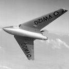
Hi all and this is my latest finish for the 'Century Series' GB here on the site. The short build thread is here but to recap: Kit: Trumpeter#01605 North American F-107A Ultra Sabre Build: OOB Paints: Tamiya acrylics; Klear; Oil pin wash. Extras: Some extra stencils from spares Notes: Canopy fit needed some surgery; the intake doesn't fit quite right; some detail inaccuracies; very few decals (all the red is painted!). But very happy how it turned out and great to build something different. Trumpeter_F107_Super_Sabre (7) by Dermot Moriarty, on Flickr Trumpeter_F107_Super_Sabre (11) by Dermot Moriarty, on Flickr Trumpeter_F107_Super_Sabre (10) by Dermot Moriarty, on Flickr Trumpeter_F107_Super_Sabre (2) by Dermot Moriarty, on Flickr Trumpeter_F107_Super_Sabre (5) by Dermot Moriarty, on Flickr Trumpeter_F107_Super_Sabre (9) by Dermot Moriarty, on Flickr Thanks for looking and happy modelling. Dermot
-
Hello, I'm currently finishing a Special Hobby N.A. BT-9 in the KUTA group build, see the links if you are interested: While applying the decals supplied I found myself with three sets of individual numbers '292', two are for the wing leading edge like in this example: I don't know what to do with the third one, nothing can be found in the instructions. Then I studied again a high resolution version of the only image I have of '292' and noticed a shadow over the underwing 'ARMY'. Maybe it shows where the third decals goes? Here are the intructions for reference, hope to not breach any forum rule linking to a commercial site https://www.super-hobby.hu/zdjecia/9/4/2/1152_2_SPH72069_4.jpg Thank you!
-
F-6C Mustang Expert Set (70040) 1:72 Arma Hobby The P-51D was developed by the North American Aviation company as a fighter for Great Britain, but due to the poor performance of the engine that was initially fitted, it wasn’t all that good at higher altitudes. Fortunately they slotted a Rolls-Royce Merlin engine into the airframe and it brought out the best of its design, which included the energy efficient laminar flow wing that gave it the potential to escort Allied bombers all the way to Berlin with the addition of drop-tanks and a lean fuel mixture when not in combat. It was flown in this guise as the Mustang III in British service, and as the P-51B/C in US service, then as the P-51D with the bubble canopy and cut-down aft fuselage, with an additional fin-fillet added later to improve stability that had been reduced by the new shape and fuel tank location. The F-6C was developed from the B/C variants, most of which were built in the Dallas factory, with openings for two cameras in the fuselage, with one camera mounted obliquely in the side of the rear fuselage, firing to the left, and the other mounted underneath, just aft of the radiator flap. Apart from some other minor changes the aircraft was fully combat capable, so didn’t need an escort to carry out its assigned task, and some of its pilots became Aces flying recon. The Kit This is a retooling of Arma’s original 2021 release to depict the reconnaissance variant of the Mustang, and as it is the Expert set, it’s the top-of-the-line boxing. It arrives in a sturdy end-opening box with an attractive painting of the subject on the front, plus profiles of four of the decal options on the rear. Inside are two sprues in grey styrene, a single clear sprue, a small fret of Photo-Etch (PE), a sheet of pre-cut kabuki tape masking material (not pictured), a large decal sheet, and an A5 portrait instruction booklet with full colour profiles on the rear pages. Detail is stunning for the scale, and the finish of the exterior surface is a pristine satin texture with some areas left glossy, an example of which are the lenses of the underwing identification lights on the starboard wing. Construction begins with the cockpit, which will be familiar to anyone who has built a Mustang before. The stepped floor has the seat, armour and support frame added to the front section, with PE belts supplied for your use, and a choice of bucket seat or tubular-framed type for your use. The rear of the cockpit can either be filled with the original fuel tank with radio on a palette on top, or three other configurations for your consideration. Decals are included for some of the radio boxes, and the finished assembly should look good with sympathetic painting. The pilot has his control column added and two dial decals applied to the floor, with more decals for the highly detailed instrument panel that is fixed below the coaming and has the rudder pedals glued to the back as shown by a scrap diagram. The cockpit sides are also detailed with additional parts, a copious quantity of decals to portray the instruments, and some adaptations to the fuselage sides to cater to your chosen decal option. The radiator pathway is also made up, adding a PE grille to the front of the bath, and another to the oval intake before it is inserted into the starboard fuselage side. The port side is prepared to receive the cockpit and tail wheel, beginning with the instrument coaming, then the cockpit assembly and tail wheel, closing up the two halves to complete the task. The wings are next, beginning with the centre of the main gear bay and a section of the spar. This is inserted into the upper wing half, and a detailed diagram shows how the bay roof should be painted correctly, which is best done before closing up the wing halves and inserting the separate flap sections, which you are advised to paint before insertion, as they also have a decal around the halfway point. Unusually, both wing surfaces are full-width, in much the same way as the real thing, and after adding some internals, the wings and fuselage are joined with a choice of either a filleted tail, or the earlier unfilleted tail, which you get to choose by using different fin and elevator parts with moulded-in fairings. Some panel lines behind the cockpit should be filled depending on your earlier choices, and this might be easier done before adding the wings. The main gear consists of a strut with single wheel and a captive bay door attaching to the leg, which slots into a socket in the outer edge of the bay, with a pair of inner doors fitted to the centre-line. The airframe is ostensibly complete, but some small parts and assemblies are yet to be added, such as the radiator cooling flaps under the rear, pitot probe under the wing, a pair of bomb-shackles outboard of the main gear bays, and a pair of lips for the chin and main radiator intakes. The perforated grille on the lower nose is slotted into its aperture, a choice of two types of exhaust stacks, two types of antenna masts plus an optional D/F loop with fairing are fixed in place around the same time as the prop, which consists of four blades moulded as one, with a two-part spinner hiding a small washer that can be used to hold the prop in place and retain the option to spin it if you so wish. There are two styles of canopy supplied for your model, so choose the correct type for your decal option, both of which have the option to portray them open or closed. The older straight hood consists of the windscreen with a section of the fuselage moulded-in, the canopy and the two scalloped rear-view panes, with the optional parts provided to display the canopy opened to the sides, assisted by a couple of scrap diagrams nearby and a warning decal for the inner lip. The later Malcolm hood is the second option, with a blown canopy that gives the pilot more room to move his head for better situational awareness. This option firstly requires removal of some small bumps on the spine behind the canopy. There are parts supplied to portray the canopy rail, and these are shown correctly applied in scrap diagrams to assist you getting it right. The final choice is to hang paper fuel tanks, metal fuel tanks or bombs under the wings, all of which are made from two halves each and have stencil decals supplied from the sheet. Markings There are a generous six decal options in the box, two of which are a bonus for this boxing. From the box you can build one of the following: F-6C-10-NT Mustang 44-10889/R7-N, GR II.33 Savoie, French Air Force, April -May 1945 F-6C-1-NA Mustang 43-12400/ZM-O, Cpt E B Blackie Travis, 12th Tactical Reconnaissance Sqn., 67th Tactical Reconnaissance Group, Middle Wallop, England, Spring 1944 F-6C-5-NT Mustang, 42-103604/600 Lt. Col. E O McComas, 118th Tactical Reconnaissance Sqn., 23rd Fighter Group, Chengkung, China, Dec 1944 F-6C-1-NA Mustang, 43-12404/266, 26th Fighter Sqn., 51st Fighter Group, China, 1944-45 F-6C-5-NT Mustang, 42-103604/600, Maj. E O McComas, 118th Tactical Reconnaissance Sqn., 23rd Fighter Group, Chengkung, China, Oct 1944 F-6C-1-NA Mustang, 43-12330/263, 26th Fighter Sqn., 51st Fighter Group, China, 1944-45 Bonus Decals Decals are printed by Techmod, which is a guarantee of good registration, sharpness and colour density, with a thin gloss carrier film cut close to the printed areas. Conclusion Another superbly well-detailed kit from Arma that makes this 1:48 modeller more than a little bit envious. Detail is excellent throughout, and the instructions are concise to help you with your build. Very highly recommended. Review sample courtesy of
-
RAAF PR CAC CA-18 Mk.22 Mustang Conversion Set (RRR48185 for Eduard) 1:48 Red Roo Models During WWII the Commonwealth Aircraft Corporation (CAC) manufactured 200 North American Mustangs under licence as the CA-18, and of these a small number were converted to Photo Reconnaissance variants that carried two F24 cameras vertically and obliquely in the rear fuselage. There were various differences between US-built and Australian airframes, and the PR variant diverged further, having bespoke fairings for the camera apertures that aren’t readily available in mainstream kits. The Set Red Roo specialise in Australian aircraft and provide modellers with conversion sets and upgrades that allow us to make more accurate models with all of the time-consuming research already done for us. Their sets aren’t ostentatious, usually arriving in a Ziploc bag, but the contents and instructions are concise and absolutely suitable for the task at hand. This set is no different, including thirteen resin parts in another Ziploc bag, and a sheet of custom decals for the included example airframes that can be found at the rear of the six-sheet A4 instruction booklet that is stapled in portrait form. The parts are as follows: 1 x CAC Moulded plywood pilot seat 2 x CAC 8-spoke wheels 1 x Spinner front 1 x Spinner back plate 4 x DHA Cuffless Propeller Blades 1 x vertical Camera Port 1 x Oblique Camera Port 1 x Decal Sheet The instruction booklet is essential to successful completion of the conversion, as it is verbose in describing the various alterations that need to be carried out on the base Eduard kit. Some scribing of access panels will be required on the fuselage sides, which have diagrams showing the location and size of each one on the sides. The two camera ports don’t need any alteration to the kit, as they are designed to be applied to the surface, using gloss black paint to represent the optical lenses, although the underside lens can be modelled covered over by a retractable shutter by overpainting it fuselage colour and installing a short rod in a slot that replicates the locking stud. There were three crosses painted on the port wing that when matched with crosses on the canopy glass would ensure that the camera was pointing in the right direction when pressing the shutter release. The Xs on the glass can be replicated by scraping with a pin then rubbing acrylic black paint into the grooves and wiping the remainder away before it dries. Additional notes can be found after the initial instructions that detail the localised radio gear, alternate battery location and the CAC wheels, as well as some corrections and information as to the configuration that Mustangs were typically parked in by their pilots after a mission. The back four pages give guidance on applying the decals and profiles of the decal options that are included on the sheet from both sides, while the standard top and bottom view are found on the last of the pages above a photo of one of the real airframes, although some smaller photos near the profiles are also included. The decals are in good registration, sharpness and colour density, with a thin gloss carrier film cut close to the printed areas. Conclusion If you want to build an accurate CAC PR Mustang in 1:48, this set will be essential to get the details right, helped immensely by the comprehensive instructions. Highly recommended. Review sample courtesy of
-
Mustang P-51D-20 & CAC Mustang Upgrade Set (RRR48178 for Airfix) 1:48 Red Roo Models Mustangs and Commonwealth Aircraft Corporation (CAC)-built Mustangs were used by the RAAF during WWII in the Pacific, but even commercial boxings that depict aircraft in that theatre generally only pay lip service to being correctly configured to actually portray those aircraft, and the devil is most definitely in the detail. Red Roo specialise in Australian aircraft and provide modellers with conversion sets and upgrades that allow us to make more accurate models with all of the time-consuming research already done for us. Their sets aren’t ostentatious, usually arriving in a Ziploc bag, but the contents and instructions are concise and absolutely suitable for the task at hand. This set includes parts and raw materials that will provide parts for the conversion, as follows: 10 x Brass Front Rocket Mounts 10 x Brass Rear Rocket Mounts 1 x Resin SCR-695A IFF Radio unit 1 x 0.013” (0.33mm) V-shaped wire 1 x 0.010” (0.25mm) x 0.060” (1.5mm) styrene strip x 10mm (not pictured) 1 x 0.020” (0.4mm) x 15mm Brass Wire (not pictured) There’s a little mixing of Imperial and Metric measurements there (the bracketed figures are mine) and elsewhere in the instructions, but we’re all of an age where we can probably handle either, and if not it’s just a Google away. The instructions are key to the operation, and consist of eight sides of A4 stapled into a short, useful booklet. It is colour printed, and also includes various drawings and photos that will assist in getting the job done, which includes the following tasks: installing the IFF Radio in the cockpit and making up a locking strip Adding an inertia switch and indicator light on the back of the seat’s head armour Putting the SCR-695A antenna in the lower wing Adding missing parts around the intake that most 1:48 kits have left out Fashioning a battery ventilation intake on the cowling Creating a circular or rectangular gun camera aperture in the wing leading-edge Adding an engine oil breather & flare tube to the fuselage side Installing up to 10 brass underwing zero-length rocket launch rails Making a static port on each side of the rear fuselage & adding a static wick under the tail The rocket launch rails are cast in two fans of brass parts, and it is worth noting that they’re different from each other, one fan full of front rails, the other with rear rails, which you can identify by the accompanying drawings. The styrene rod (not pictured) is used in conjunction with the brass wire (also not pictured) to create the tie-down strap for the IFF radio, drilling holes in the strip to glue over the wires. As well as being verbose in assistance with construction, you are also given colour suggestions, and even hints and tips on how to create your masterpiece, with the photos and drawings of particular use. Conclusion A useful set that will improve the accuracy of your Mustang, whichever 1:48 brand you choose, although the Airfix kit is mentioned most regularly. It’s always nice when everything you need is in the bag right from the outset, without needing to hunt around, just bring your talent and some tools, and everything should be just fine. Highly recommended. Review sample courtesy of
-
Canadair Sabre Mk.4 Cockpit & Airbrakes (4445 & 4448 for Airfix) 1:48 CMK by Special Hobby Airfix’s new(ish) Sabre has been around now for a while, and some folks have complained about a bit of soft detail in places, especially the rear deck behind the pilot’s head. CMK have created a number of resin sets to improve on the base kit, of which we have two sets in for review. Both sets arrive in their standard yellow blister packs with a card header, and the instructions sandwiched between the two halves. Both sets have Photo-Etch (PE) that are separated from the resin parts by a sheet of thick acetate, to avoid damage during shipping. Cockpit Set (4445) This set contains twenty-one resin parts, a fret of PE and a small printed piece of acetate sheet. It replaces the kit cockpit completely with a new resin tub, into which the replacement resin seat and PE seatbelts are fitted, along with the three-layered resin/acetate/PE instrument panel, which has additional PE controls added after has been laminated, and before it is inserted into the front of the tub with the control column. The pilot’s headrest is glued to the armoured upstand and spaced out with another resin part, then the replacement rear deck is joined to the rear of the tub. The fuselage internal sidewalls are sanded/scraped down to accommodate the new resin inserts, and the front coaming is improved by the addition of two small resin parts on the aft corners plus the gunsight, and the while there aren’t any shapes printed on the acetate sheet for the glazing, a little bit of research should allow you to make the parts from the off-cuts around the instrument panel. The kit canopy is last to be augmented, having a well-detailed resin insert to replace the simplistic internal structure, although it does reuse the clear ADF-loop cover from the kit sprues. The final part is the addition of a PE rear-view in the top of the roll-over hoop, which will need some chrome paint adding to simulate the silvered glass. Air Brakes (4448) Containing eight resin parts and a small sheet of PE, this set replaces the simplified inserts that make up the air-brake bays, relegating the kit parts to the spares bin, then replaces the brakes themselves with resin parts that are overlaid on the interior with a pair of PE skins on each one, after adding the triangular resin edges to the main brake. They are then added to the fuselage after the build, with new resin actuator pistons supplied with the set holding them at the correct angle. Review sample courtesy of
-
Cavalier Turbo Mustang III (11149) 1:48 Halberd Models Conversion for Eduard P-51D After WWII, the P-51 Mustang continued to serve with the US Air Force for a while as their standard fighter, although with every day it became more out-dated due to the headlong rush of aviation technology after the advent of jet propulsion and the race to break the sound barrier. By 1957 the last Mustang left US service, and North American sold the intellectual rights to the design that they then considered worthless to Trans Florida Aviation Inc., who intended to create a high-speed executive transport by taking surplus airframes and rebuilding them as an improved two-seat civilian aircraft. The initial Cavalier Mustangs were stripped and rebuilt without their military equipment, but apart from their livery and the taller rudder fin, they were visually almost indistinguishable from the old warhorse. They were well-appointed, with new avionics and luxury interiors, were powered by an improved Merlin engine, and were available with various-sized fuel capacities that gave a range from 750 up to 2,500 miles. Around 20 were made of the initial mark, then the Mark II was designed, with tip-tanks for extra range and various structural and avionics improvements. It was also outfitted with hard-points for weapons, and another boost to the power of the Merlin engine. Some of these were sold to Asian and South American countries, where some El Salvadoran airframes took part in the Soccer War. During this period Cavalier were actively courting the US Air Force trying to sell them the improved airframe as a Counter Insurgency (COIN) or Close Air Support (CAS) platform, but they weren’t biting, so sales were low to other customers. Soon after, they retired the trusty Merlin and replaced it with a Dart 510 turboprop, again from Rolls-Royce, although they had really wanted a Lycoming engine. It reduced the maintenance burden and was more gutsy and fuel efficient, but they still couldn’t get the US government interested. The design with the preferred Lycoming turboprop engine replacing the Dart was sold to Piper, and became the PA-48 Enforcer, but only four were made and shared so few parts with the original Mustang that there was little in the way of cost-savings from use of existing Mustang parts. Only two of the four survived the years in between, and are to be found in US museums. Many of the original Cavalier Mustangs were converted back to their original specification when Warbirds and heritage flights became popular. The Kit This is a new resin conversion kit for the Eduard P-51 Mustang in 1:48, and will convert it to the Rolls-Royce Dart equipped Turbo Mustang Mk.III that was unsuccessfully marketed to the US Airforce, and we’ve already reviewed the original Mk.I and Mk.II Cavalier conversions that carried piston engines here, which has the same preamble for obvious reasons (my laziness, and a shared story). It was an evolutionary dead-end, but looks pretty awesome, so I for one am extremely pleased to see this conversion kit, resigning the old set by the now defunct Heritage to the bin where it belongs. You can buy the set in a box with some Eduard Overtree sprues, or separately in a smaller white box if you already have a candidate kit in your possession. The conversion arrives in the aforementioned white box with a large sticker and a profile of the aircraft on the front, plus logos and a link to their eBay shop in red. Inside are 24 resin parts in Halberd’s signature green resin, surrounded by bubble-wrap and Ziploc bags, with the two large replacement fuselage parts taped together and encased in bubble-wrap to keep them safe and aligned during shipping and storage. In addition to the resin is a small set of decals on white backing paper, plus three pages of A4 instructions printed in colour on both sides. The parts are expertly cast, and the fuselage parts have all the detail of the Eduard parts, carried over flawlessly onto the new nose that extends from the front of the canopy. The new and old details are perfectly matched, which is very impressive, given the finesse of the originals – kudos indeed. This finesse is carried through to the large square-tipped prop blades, the oval side-mounted exhaust and the antennae that are attached to the new taller tail fin. As usual, take care with sanding resin, as the fine dust can be hazardous to your health if you breathe it deep into your lungs. Wearing a mask and wet-sanding will help keep you safe, and carrying out the task outdoors would be ideal. Construction begins with adapting the seat to remove the head armour, adding it and the new resin rear passenger seat to the cockpit along with the headrest as part of building the kit cockpit with whatever upgrades you may or may not wish to apply from other sources. The new fuselage needs little in the way of clean-up, but ensure it is done before you begin adding the kit parts, and remember to use CA to glue them, as resin cannot be bonded together or with styrene parts by our usual plastic glues. Not even the mighty Tamiya Extra Thin can do the job. Epoxy resin can be used for large parts if structural strength is needed, but it’s slippery stuff and takes 5 minutes for initial cure, so needs to be held in place with tape or clamps, whereas CA generally bonds almost instantly. It’s your choice of course. At the tail the fin has been adapted ready for the extended tip, and you should drill two 0.2mm holes in the sides for the antenna on each side. The fin fillet from the kit will fit in the gap at the leading edge of the tail, and the kit rudder will fit too once you have removed a short section from the top, using the new fin top as your guide. The kit canopies are used, but with the stiffening hoop omitted to avoid decapitating the passenger and a new resin part at the rear, while the windscreen loses its rear-view mirror. Going back to the fuselage, the front is finished with another fine resin part, with a top intake and a small gap between the cowling and the gearbox housing, with some fine stators visible at the back of the space. The prop boss has recesses for the four blades cut into its sides, and a peg that mates with the recess at the centre of the nose for easy installation. The prop blades however aren’t keyed, so you will need to set the angle yourself to ensure they are all correctly aligned and facing the right way. It may be an idea to create a small temporary jig to help with this. The large exhaust is fitted through an oval opening in the starboard side of the fuselage, and the inner end butts up against a recess inside the nose, so insert that before you get too far ahead of yourself and can no longer see the part’s destination. The kit wings are built up as normal, but have the front section under the nose removed back past the curved section of the root fairing, and the wingtips too, both as shown in red on the instructions. Take care here, because the centre section is shown being removed in steps in two separate diagrams, which could lead to some confusion. The tip tanks have their fairings and a shallow peg to mate to the open wingtips, and they are moulded with the nose separate to allow them to be cast as smooth as possible. I have cut one of the parts free on the previous set, and with careful fitting, the noses can be mated perfectly to the main tank section. Just take some time and care with sanding and test-fitting the joints. The pylons for the numerous weapons the Turbo Mustang could carry are attached to the underside of the wing on pins, and you should first measure and drill the holes, preferably before you have completed the wing, so take care there too. There are six pylons in total, two from the kit, and four resin parts from the conversion, all of which are set 13.5mm apart in a line. I’ve also marked these out on a kit wing and drilled them out, so it’s not so hard. The rest of the kit is put together in the same manner as the Eduard instructions suggest, but it will be key to your success to familiarise yourself with both sets of instructions to ensure you know exactly where all the parts go, and at which stage in the build you should insert them into the model. Markings There were only a few of these aircraft made, so there aren’t many options unless you’re going to go with a “what-if” scheme. From the box you can build the following: Cavalier Turbo Mustang III, Sarasota, Florida, 1968 The colour call-outs use FS numbers and colour names, and the few decals are shown in an enlarged form where necessary to save straining your eyeballs. The decals are well-printed with a thin carrier film, and a small arrow is printed next to the step-marks on the wing roots so that you fit them correctly. Stencils for the large prop blades are included, as are a selection of RR logos and fire warning stencils. My example had two decal sheets in the bag, but yours may not, so don’t assume. Conclusion The previous sets were excellent, but the sheer weirdness of the nose of this version makes me unreasonably happy, and the fact that it has been so well done almost brings a lump to my throat. You really need one for your stash, and to encourage Halberd to create more excellent oddities to fill our cabinets and stashes with interesting aircraft and their lesser-known derivatives. Extremely highly recommended. Halberd Models sell their products via eBay for their ease, and the link below will take you to their shop there. Review sample courtesy of
-
P-51K Mustang ProfiPACK (82105) 1:48 Eduard The P-51D was developed by the North American Aviation company as a possible fighter for Great Britain, but due to the poor high-altitude performance of the engine initially fitted it wasn’t all that good. Luckily, it occurred to them to substitute a Rolls-Royce Merlin engine into the airframe and it brought out the best of its design, which included the energy efficient laminar flow wing that gave it the potential to escort Allied bombers all the way to Berlin with the addition of drop-tanks and a lean mixture when not in combat. It was flown in this guise as the Mustang III in British service, and as the P-51B/C in US service, then as the P-51D with the bubble canopy and cut-down aft fuselage, with an additional fin-fillet added later to improve stability that had been reduced by the new shape and fuel tank location. D models that were made in Dallas were given the K designation. This is the Mustang that most people think of when they hear the name, unless they’re more of a petrol head or a bit horsey. The Kit We were initially treated to the ProfiPACK, Royal Class and Weekend forms of this new tooling and now it’s everyone’s favourite Mustang in 1:48 (with good reason), with an increasing number of variants with filleted and unfilleted tails being the most obvious differences, but it goes a lot deeper and more subtle than that. We’re now in receipt of a handsome K specific variant, which includes a pair of nice decal sheets with 6 markings options, some from unusual locations. Inside the box are five sprues in blue/grey styrene, a clear sprue, a fret of Photo-Etch (PE) brass with nickel-plating and much of it pre-printed both in colour and with domed clear instrument faces, kabuki tape masking sheet (not pictured), two decal sheets and a thick instruction booklet with the marking options printed in the rear in colour. Construction begins with the seat, which is built up first with PE belts, then the cockpit floor, tanks and radio gear are added in, with sidewall framework dotted with PE parts on both sides. It shapes up to be a well-detailed cockpit, and the PE parts are numerous and impressive. The tail-wheel bay is made up, the radiator pathway and a spinner backing-plate are all slipped into the fuselage along with a PE grille and exhaust backing panel before they are closed up. The wheel bays are built up next with some advice regarding colour added along the way, splitting the bay down the middle and bracketing it front and back with bay walls that have partial ribs added once in place, and here I can vouch for the fact that fit is exceptional, with the joints expertly hidden once complete, and incredible accuracy of tooling. This assembly is fitted to the full-width lower wing and joined by backing panels to the spent brass chutes, a central insert that shows through the bay, and a clear part for the identification lights. The wing uppers go on and the ailerons fit into tabs in their recesses, with some room for offsetting if you wish. On the leading edge is an insert for the guns, and you’ll need to fill a few panel lines under the nose and scribe one using the template supplied on the PE sheet. There are also a complement of holes that will need opening up if you’re fitting drop-tanks, so have a pin vice to hand. The wings are mated to the fuselage, and tiny clear wingtip lights are slotted in on long stalks, then the tail fins are begun. The filleted fin is a separate insert and elevator fins with two types of flying surfaces are inserted into slots horizontally, while the rudder can be fitted at any sensible angle. You may have noticed the lack of comments about the instrument panel during building of the cockpit, but we’re getting to it now. The finished coaming and rudder pedals drop into the fuselage, but are first decked out with a multi-layered instrument panel made from pre-painted PE, with those glossy instrument dials we've come to expect from Eduard, and a small deck behind the pilot. The two radiator doors under the tail are fitted at the same time as the tail wheel, with bay doors and PE closure mechanism added along the way, with a scrap diagram showing the correct orientation. Inside the main bay a pop-up landing light is slotted into its mounting point, a PE divider is added to the exhaust intake lip, and chin-scoop plus the correct panel under the nose (decal choices again), then it’s on to the main gear legs. The tyres are diamond tread, with wheels and hub caps added before they’re fitted to the struts, which have separate styrene scissor-links and door supports slotted into place. The flaps are each made up from two styrene layers with a tiny piece of PE added to the inner end of each one and a decal on the curved leading edge after painting. You’ll have to remember to add these yourself, as I won’t be any help! Those are all slotted in place on the underside along with the rest of the bay doors, and at that point you can sit her on her wheels and add the exhaust stacks. The prop is made from two paired blades that fit perpendicular to each other in a choice of two types of blades (cuffed & uncuffed) and spinner, canopy with interior structure, and a backup ring and bead sight. There’s also a choice of aerials and D/F loops on the spine behind the canopy, which of course depends on your decal choice. The weapons and drop tanks are last to be made, with a choice of three tank types that all share the same type of pylon, while one has additional supports to the sides. A few spares are left on the sprue, including a set of six rockets for under the wings, which have separate tails and moulded-in launch-rails that would be fitted three per side. All useful grist for the spares mill. Markings By now you should have your decal choice dialled in. You have a half dozen choices, and they’re quite colourful. The two sheets are separated between the individual markings and standard stencils. From the box you can build one of the following: P-51K-5, 44-11622, Maj. Leonard Carson, 362nd FS, 357th FG, 8th AF, Leiston, UK, August 1944 P-51K-5, 44-11661, Lt.Col. Jack J Oberhansly, 334trh FS, 4th FG, 8th AF, Debden, UK, February 1945 P-51K-5, 44-11631, Lt. Huie Lamb, 82nd FS, 78th FG, 8th AF, Duxford, UK, March 1945 P-51K-1, 44-11471, LKt. Carl H Colleps, 118th FRS, 23rd FG, 14th AF, Cheng Kung, China, 1945 P-51K-10, 44-12539, Lt. Everett Kelly, 6th FS, 1st Air Commando Group, 10th AF, Asansol, India, Summer 1945 P-51K-10, 44-12073, Lt.Col. William M Banks, Co of 348th FG, 5th AF, le Shima, July 1945 Decals are printed in-house with good registration, sharpness and colour density, with a thin gloss carrier film cut close to the printed areas. The stencils are dealt with on the back page in the instructions to prevent clutter and replication of effort, and also shows the various metallic and fabric covered sections for the "unpainted" decal options on another page. Conclusion We already know the quality of the basic kit, and this box has some interesting markings that will please a lot of people. You just have to narrow down the decal choices to one… or get some Overtrees again perhaps? Highly recommended. Review sample courtesy of
-
Eduard Sabre F.4 Wheels (648673 for Airfix) 1:48
Mike posted a topic in Aftermarket (updates/conversions)
Sabre F.4 Wheels (648673 for Airfix) 1:48 Eduard Brassin Kit wheels are generally in two halves, which means you have the resultant joins to deal with, possible mould-slip issues on single part wheels, and sometimes less than stellar detail due to the moulding limitations of styrene injection technology, especially in the tread department. That's where replacement resin wheels come in, with their lack of seamline and superior detail making a compelling argument. They are also usually available at a reasonable price, and can be an easy introduction to aftermarket and resin handling, as they are usually a drop-in replacement. This set arrives in the usual Brassin-themed flat pack, with a white backing card keeping the package square and the instructions wrapped around it inside. The wheels are each separate parts on their own casting blocks, while the two protruding inner hubs are to be found on another block together. The detail is excellent throughout, with tread, maker’s name and technical details on the sidewalls, plus a slight sag at the bottom where the casting block attaches. This makes for easy removal, as it is the part that won’t be seen, so if you’re a bit rough with it no-one will see anyway as long as it’s flat. The nose wheel has deep spoke detail moulded on both sides, with all wheels having a deep hole in the rear for attachment to the kit gear legs. In addition, a set of kabuki tape masking material (not pictured) that is pre-cut for your convenience is included, allowing you to cut the demarcation between tyre and hub cleanly and with little effort. Review sample courtesy of -
P-51K Mustang Upgrade Sets (for Eduard) 1:48 Eduard We’ve recently reviewed the new boxing of this appealing and capable WWII Allied fighter, and it’s just as good as the others we’ve seen since the initial release. Eduard's new range of sets are here to improve on the kit detail in the usual modular manner. Get what you want for the areas you want to be more of a focal point. As usual with Eduard's Photo-Etch (PE), Brassin resin and Mask sets, they arrive in a flat resealable package, with a white backing card protecting the contents and the instructions that are sandwiched between. SPACE Cockpit Set (3DL48037) The Eduard SPACE sets use new 3D printing techniques that lay down successive layers of different colour resin, creating highly realistic almost full complete panels that are supplied on a decal sheet. They can depict metallic shades, plus glossy, satin and matt colours too, which really ups the detail on everything they print. In addition, a small sheet of nickel-plated and pre-painted PE is included for the aspects of the set that lend themselves better to this medium, such as seatbelts and rudder pedals. The 3D decal sheet contains a main instrument panel with a number of additional shaped panels to be fitted around the cockpit, plus placards and dials aplenty. The PE sheet has the four-point seatbelts for the pilot, levers for the instrument panel, backup ring-and-bead gunsight, and other small parts. Seatbelts STEEL (FE1214) These belts are Photo-Etch (PE) steel, and because of their strength they can be etched from thinner material, which improves realism and flexibility in one sitting. Coupled with the new painting method that adds perceived extra depth to the buckles and other furniture by shading, they are more realistic looking and will drape better than regular brass PE. As in the 3D cockpit set above, the small fret contains the four-point belts with comfort pads and latch detail. Tface Masks (EX801) Supplied on a sheet of yellow kabuki tape, these pre-cut masks supply you with a full set of masks for the canopy both inside and out, with compound curved handled by using frame hugging masks, while the highly curved gaps are in-filled with either liquid mask or offcuts from the background tape. In addition, you get a set of hub/tyre masks for the wheels, allowing you to cut the demarcation perfectly with little effort. Review sample courtesy of
-
Cavalier F-51D Mustang/Mustang II Complete Kit & Conversion Kit 1:48 Halberd Models After WWII, the P-51 Mustang continued to serve with the US Air Force for a while as their standard fighter, although with every day it became more out-dated due to the headlong rush of aviation technology after the advent of jet propulsion and the race to break the sound barrier. By 1957 the last Mustang left service, and North American sold the intellectual rights to the design to Trans Florida Aviation Inc., who intended to create a high-speed executive transport by taking surplus airframes and rebuilding them as an improved two-seat civilian aircraft. The initial Cavalier Mustangs were stripped and rebuilt without their military equipment, but apart from their livery and the taller rudder fin, they were visually almost indistinguishable from the old warhorse. They were well-appointed, with new avionics and luxury interiors, were powered by an improved Merlin engine, and were available with various-sized fuel capacities that gave a range from 750 up to 2,500 miles. Around 20 were made of the initial mark, then the Mark II was designed, with tip-tanks for extra range and various structural and avionics improvements. It was also outfitted with hard-points for weapons, and another boost to the power of the Merlin engine. Some of these were sold to Asian and South American countries, where some El Salvadoran airframes took part in the Soccer War. During this period Cavalier were actively courting the US Air Force trying to sell them the improved airframe as a Counter Insurgency (COIN) or Close Air Support (CAS) platform, but they weren’t biting, so sales were small to other customers. Soon after they chopped off the Merlin and replaced it with a Dart 510 turboprop, again from Rolls-Royce, although they had really wanted a Lycoming engine. It reduced the maintenance burden and was more gutsy and fuel efficient, but they still couldn’t get the US government interested. The design with the preferred Lycoming turboprop engine replacing the Dart was sold to Piper, and became the PA-48 Enforcer, but only four were made and shared so few parts with the original Mustang that there was little in the way of cost-savings by using existing parts. Only two of the four survived the years in between, and are to be found in US museums. Many of the original Cavalier Mustangs were converted back to their original specification when Warbirds and heritage flights became popular. The Kit Just like Halberd’s recent Bf.109W floatplane that we reviewed here, this model is available as a conversion kit only, or as a full kit in an Eduard Overtrees box so that you can either apply the conversion to a kit you already possess, or get the full package in one fell swoop. The difference in price between the two is about the same as the cost of the overtrees kit, so there’s nothing to stop you from choosing whichever one is most suitable for your needs. Within the box are twelve resin parts in Halberd’s signature green resin, plus a grey styrene sprue, and two new decal sheets. With the full kit (larger box), you also get the five Eduard grey/blue sprues and circular clear sprue in the box, which you can see below, culled from our reviews of this excellent kit. Resin & Styrene Conversion Parts Eduard Donor Kit (if applicable) You can also go through the details of the build of the base kit by following any of our Eduard P-51D reviews in this section. Suffice to say, this is our current favourite 1:48 Mustang since it came out. Highly detailed, crisp and with a growing range of options, as well as aftermarket upgrades. The Conversion We’ll assume that you’re now au fait with the contents of the Eduard box, so we’ll concentrate on the alterations made by the conversion kit. You get a full set of instructions printed in colour on both sides of two pages of A4, plus three pages of profiles for the four decal options, including the undersides on the back page. The Eduard instructions are available on their site by looking up kit numbered 82102 or clicking here. The conversion begins with cutting off the head armour and headrest from the seat, then where the radio gear would have been in the cockpit floor, the two lugs are removed and the rear seat is inserted from a part on the kit sprues, with a small resin headrest attached to the top. The tip of the rudder and fin get the chop, and are replaced by the new fin-tip, with a pair of large swept blade antennae inserted into holes in the fin on both sides. The lower wing will need a set of holes drilling if you are fitting the combination of kit and resin pylons for decal option 4. The innermost pair of holes are pre-thinned from the inside, but you will need to mark out the other four using the measurements provided on the instructions, spacing them 13.5mm apart from the inside. Again, for markings option 4, you will need to remove the original wingtips from the finished wings and use the resin tip-tanks, which have separate nose cones and a tiny resin vent on the top, with the kit tip lights slipped into a hole in the outer sides, which may need drilling out. The instructions then guide you through choosing the correct circular exhausts and the cuffed props, followed by the appropriate blown canopy and a tiny resin insert in the very rear frame of it. You also shouldn’t include the stiffening hoop inside the canopy, as you’ll slice off the passenger’s head when you open the canopy! As you’re not under threat of attack, the rear-view mirror can stay in the spares box too. The light grey sprue of styrene parts comes into play here, utilising just the two tanks to fit on the kit pylons for markings 1 and 2 only. Each one builds up from two halves and will need a little sanding to get rid of the join lines before you fit them. For markings option 4, the three pylons are inserted into the holes drilled earlier and it’s up to you what you load them with, if anything. Markings As already mentioned, there are four decal options, three of which are F-51D Mustangs, the last an F-51D Mustang 2 with the tip tanks, which happens to be my favourite option, other than the Enforcer. From the box you can build one of the following: Cavalier Mustang F-51D US Air Force Sarasota, Florida, 1968 Cavalier Mustang F-51D Bolivian Air Force, 1971 Cavalier Mustang F-51D Bolivian Air Force, 1972 Cavalier Mustang F-51D Mk.2, Fuerza Aérea Salvadoreña, El Salvador, 1969/70 The decals are printed anonymously with good registration, sharpness and colour density, with a thin matt carrier film cut close to the printed areas. Conclusion I’ve been wishing for a good Cavalier Mustang for years now, and this set/kit ticks all of the boxes, and includes a generous four decal options into the bargain. Based upon the excellent Eduard kit, it doesn’t get much better. Very highly recommended. Halberd are currently marketing their products via eBay, so the links below lead to their site. Full Kit & Conversion Conversion Parts only Review sample courtesy of
-
Hello Everyone... As my Condor Legion Ju.86 is nearing completion I will be gearing up for my next build. This will be Trumpeter’s 1/72 North American F-107A UltraSabre. This would have been built of course for the North American group build. I project a start sometime in the next week or so. Here are the sprue shots from a previously unopened kit. Ive done quite a bit of research with @72modeler and 99% sure will be going with the test scheme. Im not actually inspired by the test scheme and I still leave 1% open to a possible Whif scheme. I would need to find decals though for such a scheme. Most likely a former F-100 unit, or possibly F-105 unit from Europe circa early 1960’s. The theory being that these were competing with Republic for the same role, so F-105 units would also be good options. Maybe @RidgeRunner has some insights to this. I did reach out to him awhile ago via P/M but never got an answer. Questions, comments, and or thoughts please don't hesitate. Dennis
- 44 replies
-
- 6
-

-
- North American
- F-107
- (and 1 more)
-
Canadair Sabre F.4 (A08109) 1:48 Airfix The North American F-86 Sabre was a first-generation swept-wing jet that saw active service in Korea and beyond in US service, and was license-built by Canadair in a number of variants. Small numbers of the Mk.1, 2 and 3 were built before the Mk.4, which was destined for the RAF to fill a void in their inventory that couldn't yet be filled by indigenous types. The Mk.4 retained the GE engine, and were leased by the RAF from 1953 to 1956 as a supposed stop-gap while they waited for the Hawker Hunter, because the previous Meteors and Vampires were by that time outclassed by more advanced swept-wing jets being fielded by both our Allies and the Soviet aligned Air Forces. Curiously, some of the RAF Sabre squadrons, many of whom were in Germany at the time, eventually transitioned back to Meteors at the end of the lease. That must have been quite a come-down, akin to going from a Morris Minor to a Trabant. The airframes reverted back to Canadair, and eventually went out to other customers after being refurbished. The Kit This is a brand-new tooling of the Canadair built Sabre Mk.4 from Airfix, and there’s been a lot of excitement in the run-up to release. Since then there has been some chatter about various relatively minor issues, and as no kit is perfect that’s not surprising, but they’re pretty easy to fix once you’ve got your head round them. The Canadair Sabres have quite a following with Britmodellers due to their RAF service, so you can hardly blame them for the scrutiny. I’ve cheated and sought the advices of a Sabre aficionado, our own Sabrejet, or Duncan was we call him. Julien has chipped in a few comments as well, as he’s a bit of a Sabre fan too, with over 70 kits in his stash. Have a read of the review first, and I’ll link to the discussion thread near the end. Construction begins in an unusual place for a change, the intake trunking. It is split horizontally, and has alignment pegs on the outer edges, plus a square of four pegs on the topside to which the cockpit tub is fixed. The rear deck is moulded into the tub, and here is one of the first areas where a little work might be on the cards if it perturbs you. The details here are a little simplified, and if you’re detail focused there’s some minor changes to be made. The seat is put together from the L-shaped base, two side supports and the headbox cushion, which was usually brown, as were the armrests. As it is inserted into the cockpit tub, the instructions show it briefly with seatbelts, but there aren’t any on the sprues or on the decal sheet, so just ignore that. A pair of decals are supplied for the side consoles, and another is there for the instrument panel that slots into the front of the tub. The decals have a clear background, so you’ll be able to paint the panel in the correct colours, which incidentally should be black, rather than the Gull Grey (140) mentioned in the instructions. A very dark grey with some lighter highlights, followed by a black wash should achieve the desired effect. The control column has a gaiter at the bottom that has a separate section added to give it the appropriate width. The cockpit trunking assembly has a set of stator blades fitted to the rear along with a two-part intake bullet, and at the front you have a choice of either the hollow intake lip, or the same part with a FOD guard inserted into the trunk first, blocking off the intake for a grounded bird. Airfix have helpfully provided a pilot figure in their traditional “hands on lap” pose, and apart from the slightly passive posture, the moulding and detail is good. Flipping over the trunking, there are some ribs and equipment moulded into the underside for the nose-bay roof, which is boxed-in by a two-part wall, and should be painted interior green, while the doors should be silver. The fuselage has a couple of holes in the forward end to accept inserts, including the gun bay doors that can be closed up, or left open to show off the gun bays. The bays are a single curved box, into which the breeches of the guns fit at an angle, with the help of scrap diagrams showing the correct orientation as each one is glued into position. The magazines are inserted into the lower section of the bay, and have their ammo feeds glued to the top, leading to the gun breeches. The same process is carried out in mirror image on the other side of the fuselage, then the bays are glued in place from the inside, correctly marked as painted in silver. The airbrakes on the rear fuselage sides can also be posed open or closed by inserting a closed bay door with supporting ledges that should allow you to glue them flush to the outer skin (possibly after some fettling, so test fitting is essential), or the open bay with the bay doors fitted in the open position later, with the back of the panel painted interior green. In order to close up the fuselage you need to make up the exhaust trunk, which has the rear engine face inserted in the flared forward end, and an optional circular FOD cover over the hot end. There are two supports for the forward end that fix into sockets on the inside of the port fuselage, and a moulded-in lip near the aft end slots into a corresponding slot inside the rear, ensuring correct positioning. You are advised to put 10g of nose weight in the gap between the cockpit and intake lip, but a little more probably wouldn’t hurt, as there’s plenty of space. The cockpit & intake are also inserted into the left fuselage with the aid of sockets to hold them secure, then a long insert is placed in the area between the tail and the exhaust trunk, which also makes up the lower side of the tail fairing. If you are modelling your Sabre in-flight, you need to put in the single nose bay door insert in now, and this too has ledges to help with fitting, then you can close up the fuselage and set it aside to cure while you make up the wings. Airfix have moulded the lower wing as a full-width part, and many think they missed a trick by not adding a slatted-wing to the moulding, but we might yet see that later – who knows? Again, if you’re going for wheels-up, the single main gear bay insert should be fitted now, and this too has ledges around the edge to help with alignment. A pair of pylon holes should be drilled in each wing if you are fitting them (see my note later about positioning), and the bay walls are made up from narrow parts around the rear edge, plus a more substantial front wall that will need a pair of blocks removing if you are depicting your Sabre with the inner doors extended, as these are only used when the doors are closed, again to stop them from dropping inside the bay during fitting. There’s another nubbin under each door on the front bulkhead, so treat that the same if you’re dropping all the doors. The bay roof has two depressions moulded-in to accommodate the wheels, and this assembly is fitted into the lower wing, with additional parts installed in the outboard section, and don’t forget to give the upper wing interior a quick squirt of the same interior green, as there is roof detail moulded-in there too. If you took the decision to open up the gun bays, the very tips of the wing roots should be cut off the wing leading edge uppers along the panel line, as that section is integral to the bay door and is supplied as part of the open door parts. A scrap diagram holds your hand through this, then you can join the wing halves and fit the hard-edge leading edge lower panels with their chopped off tips if appropriate. Another hole may be needed for the drop-tanks too. The short, stocky wing fence is a little broad in the beam thanks to the limitations of injection moulding, which can easily be corrected by thinning it down, or chopping it off and replacing it with thin styrene or brass sheet planted in a razor-saw cut in the correct place. Before you can join the wings to the fuselage, there are two intakes under the fuselage that are moulded as holes in the lower wing. The inserts are installed from the inside, so fitting them later would be horrible. With that, the insert in front of the tail fin is fitted into the upper fuselage, and the wings are attached beneath, adding the L-shaped wingtip and aileron insert to the trailing edge of the outer wing as you go. The elevators are both single parts and attach with the usual slot and tab method, while the rudder is separate and can be glued deflected as you wish, but don’t forget to offset the control column to save yourself from the purists. They’ll get you! There are inserts to be added above the wing root trailing edge, then it’s gear and bay doors. If you have elected to pose your model gear up, you can skip this part, but even with the gear down you still have choices. The main bay inner doors can be posed up by using one part, or down by joining two different parts in a very sharp inverted V-shape, remembering that the short section of bay wall should be interior green, but the door should be silver. They’re supported by a short jack in the front of the bay, then the main gear leg and its captive door can be joined and inserted. Here you’ll need to remove the tiny link that has been included in error because Airfix scanned a museum airframe that either didn’t have any pressure in the strut, or was being supported to prevent sag. Some careful trimming and sanding will have it looking correct in no time, and you can carry on with putting the main wheels on, which will line up the flat-spot with the ground automatically thanks to the axles and hubs having a keyed fitting. Moving to the nose gear, there are a pair of flip-down landing lights just in front of the bay, and you can depict these in the flush position by using a clear part and masking off the circular lights, painting the rear silver before you install it, or you can use the styrene part and fit the deployed clear lights later in the build. The nose gear leg is a single part, and fits into a keyed slot in the front of the bay, and has a smaller two-part wheel slipped onto another keyed axle. A retraction jack fixes to the back of the strut, and the folded front door clips in place either side of the wheel, with a scrap diagram showing the correct location and where it links to the strut. The rear door can be posed closed or dropped sideways with a strut holding it at an angle, with that and the open lower gun bay doors shown in place on a frontal diagram for your reference, but the upper gun bay panels aren’t mentioned again, so you’ll either have to severely thin the unused closed-up inserts, or tell everyone some erk wandered off with them. The open air-brakes glue into the fuselage with their stays holding them to the correct angle, and slightly further forward next to the intakes under the fuselage you are given two small parts to locate on tiny depressions between fairing panels. These are jacking points, and were only fitted during maintenance, so unless you are planning a diorama that involves jacks, leave them in the box and if you can see the depressions, pop a tiny amount of filler in there to make them disappear. Under the tail there is a small blade to fit into another small depression, which is best left off until after main painting. There are two types of drop-tanks supplied on the sprue, a smaller pair with no fins, and a larger pair with a choice of simple fins or larger fins with a perpendicular stabiliser. I’m told that the RAF tended to use the smaller tanks, but check your references and see which style your decal choice used. They fit to the lower wing on quite stout pins, so when the instructions tell you to make 2.3mm holes, don’t skimp on the size. The big tanks have stabilising struts fitted between the body and the smaller 0.8mm hole in the leading underside panel, regardless of the style of fins. We understand that the positioning of the tanks is slightly adrift, and should actually be 52.33mm from the centre line, so if you want to get the look dead-on, you’d better get out your callipers. The model is finished off by adding the kinked pitot at the tip of the starboard wing, the optional popped-out lights under the nose, a clear gunsight, and the canopy. The windscreen is separate from the sliding canopy, and there is an insert that fits inside with a clear “lamp” at the midpoint, which is actually the radio compass loop antenna. This is a simplification of what is there, and could have been a little better, but it would have required more parts, and those details cost time and money. As it is, you have a reasonable approximation of the parts in the area, but if you have gone to the trouble of detailing the deck behind the pilot, you’ll probably want to do something similar here, detailing the support cross-member and the cockpit pressure regulator in the very rear. Once you are satisfied, the canopy can be posed open or closed to suit you. Markings There are two decal options on the sheet, and surprise, surprise! they’re RAF airframes. They are period correct schemes for the squadrons depicted, with a green/grey topside and a PRU blue underside, although the colours are printed slightly differently from each other on my instructions. Each aircraft is shown in four views, and empty space around the profiles is taken up with research notes and drawings of the drop tanks and their stencil locations. A separate sheet shows the locations of the many stencils around the airframe to avoid repetition and cluttering the pages with too many lines. From the box you can build one of the following: XB984 No.3 Sqn. RAF Germany, Geilenkirchen, 1954 XB854 No.4 Sqn. RAF Germany, Jever, 1954 Note that on the paper profiles in the kit, the fuselage codes are presented as T.B from the port side. Decals are by Cartograf, which is a guarantee of good registration, sharpness and colour density, with a thin gloss carrier film cut close to the printed areas. Conclusion It’s a welcome new tool with a few accuracy notes mentioned in the text that shouldn't stress you to fix, a couple of colour changes needed during detail painting, but it’s a Canadair Sabre F.4, something that’s been wanted by aficionados for quite some time. You can find the initial thread on the kit here. Whilst writing, thanks to Duncan (Sabrejet) for the additional information that helped enormously in writing this. Highly recommended. Review sample courtesy of
-
Hello everyone... This will be my 2nd entry into the build. Im going with the rather new 1/72 Sword FJ-3 Fury. I will be building this in my favorite set of markings for the Fury, VF-73 “Jesters.” For this I will be using a combination of Caracal decals and a custom set of decals Ive had commissioned. These are part of the custom decals, Jesters squadron logo’s in 1/72 & 1/48 and various sizing blue chequers for future builds. Here are the obligatory sprue shots. Im not exactly thrilled with multipart drop-tanks or the butt joint on the tailplanes. I will need to figure out a pin set up for them. Please feel free to ask questions, post comments, or add thoughts ? Dennis
- 37 replies
-
- 6
-
-
- 1/72 Sword FJ-3 Fury
- VF-73 Jesters
- (and 1 more)
-
F-6D/K Mustang (82103) 1:48 Eduard ProfiPACK The P-51D was developed by the North American Aviation company as a fighter for Great Britain, but due to the poor performance of the engine initially fitted, it wasn’t all that good. Fortuitously they slotted a Rolls-Royce Merlin engine into the airframe and it brought out the best of its design, which included the energy efficient laminar flow wing that gave it the potential to escort Allied bombers all the way to Berlin with the addition of drop-tanks and a lean mixture when not in combat. It was flown in this guise as the Mustang III in British service, and as the P-51B/C in US service, then as the P-51D with the bubble canopy and cut-down aft fuselage, with an additional fin-fillet added later to improve stability that had been reduced by the new shape and fuel tank location. The same "D" variant that was made at the Dallas factory with hollow AeroProducts props was designated P-51K to differentiate, and when they repurposed a number for photo-recon purposes they kept the identifications after changing the name to F-6, so there were F-6Ds and F-6Ks in about equal numbers. There were two cameras mounted in the fuselage, with one camera mounted obliquely in the side of the rear fuselage, firing to the left, with the other was mounted underneath, just aft of the radiator flap. Apart from some other minor changes the aircraft was fully combat capable, so didn’t need an escort to carry out its assigned task, and some of its pilots became Aces flying recon. The Kit We were treated to the initial release in ProfiPACK form of this new tooling and it’s now almost everyone’s favourite Mustang in 1:48, with a number of variants with filleted and unfilleted tails to differentiate them. This new boxing has some different sprues, most notably in the fuselage department to accommodate the camera openings. In total there are six sprues in grey styrene, a clear sprue, a fret of Photo-Etch (PE) brass with nickel-plating and much of it pre-printed both in colour and with clear, domed and glossy instrument faces, a set of canopy masks (not pictured), large decal sheet and instruction booklet with the markings options printed in the rear in colour. The prop blades above fell off the sprue during transit. Construction begins with the cockpit, beginning with the seat that is built up first with PE belts, then the cockpit floor, tanks and radio gear are added in, with sidewall framework dotted with PE parts on both sides. It shapes up to be an extremely well-detailed cockpit, and the PE parts are numerous and impressive. The tail-wheel bay is made up, the radiator pathway and a spinner backing-plate are all slipped into the fuselage along with a PE grille and exhaust backing panel before they are closed up. There are some minor changes required around the fuselage, beginning with an antenna hole that needs opening up, a small intake to be removed from the lower port engine cowling, and if you are doing decal option B, a small upstand and lens hole under the camera aperture will need removing and filling respectively. The wheel bays are built up next with some advice regarding colour added along the way, splitting the bay down the middle and bracketing it front and back with bay walls that have a healthy number of partial ribs added once in place. This assembly is fitted to the full-width lower wing and joined by backing panels to the spent brass chutes, a central insert that shows through the bay, and a clear part for the three identification lights, plus a couple of holes will need opening up for drop tanks if you’re using them. The wing tops go on and the ailerons fit into tabs in their recesses, with some room for offsetting if you wish, then the leading edge receives inserts for the guns. There is also a small oval inspection panel on the starboard that will need filling, a square hole in the leading edge of the wing needs opening for some decal options, and some panel line surgery will be required under the nose for other decal options, a PE template being provided to assist with this. The wings are mated to the fuselage, and tiny clear wingtip lights are slotted in on long stalks, then the tail fins are begun. The filleted fin is a separate insert and the elevator fins with their flying surfaces are inserted into slots horizontally, while the rudder can be fitted at any suitable angle. You may have noticed the lack of comments about the instrument panel during building of the cockpit, but we’re getting to it now. The finished coaming and rudder pedals drop into the fuselage, but are first decked out with a multi-layered instrument panel made from pre-painted PE. The camera lenses are inserted into their positions, and a small deck at the rear of the cockpit is installed, then the model is flipped and two radiator doors under the tail are fitted at the same time as the tail strut with separate wheel, with bay doors and closure mechanism added along the way. Inside the main bay a pop-up landing light is slotted into its mounting point, a PE divider is added to the radiator intake lip, and chin-scoop plus the correct panel under the nose (yes, decal choices again), then you must remove some tiny raised bumps forward of the flaps, then it’s on to the main gear legs. The two-part diamond treaded tyres have the hub caps added before they’re fitted to the struts, which have separate styrene scissor-links and door attachments slotted into place. The flaps are each made up from two styrene parts with a tiny piece of PE added to the inner end of each one and a coat of silver paint on the curved leading edge before installation. Those are all slotted in place on the underside along with the rest of the bay doors and some antennae, and at that point you can put her down on her wheels. The prop is made from two paired blades that fit perpendicular to each other in a choice of two types of spinner, with a couple of parts options for the different decal options, and even a choice of three canopies depending on your decal choices. The canopy has a couple of interior parts added before it is fitted, then the windscreen and PE backup-sight on the coaming, a choice of tubular exhausts or the more prominent angled style. There’s also another optional aerial on the spine for one of the decal choices and a d/f loop for three others, plus an optional PE aerial with base and the traditional mast behind the canopy. The final building decision is whether to fit drop tanks, and if so which type? There are two pairs of tank types that fit either fit flush to the shallow pylon, or with one of two types of flat supports either side of the pylon, hiding some nice anti-sway braces that are glued into the pylons earlier. Markings By now you should have your decal choices long decided upon. You have six choices, and they’re all based on a bare metal airframe with silver lacquered wings. From the box you can build one of the following: F-6D-15, 44-14874, flown by Lt. John E. Jacoby, 82nd TRS, 71st TRG, 5th AF, Johnson Field, Japan, September 1945 F-6D-10, 44-14699, flown by Lt. Clifford S. Slonneger, 109th TRS, 67th TRG, 9th AF, Gosselies, Belgium, 1945 F-6K-10, 44-12223, 118th TRS, 23rd FG, 14th AF, Chengkung, China, 1945 F-6K-15, 75th FS, 23rd FG, 14th AF, Luliang Airfield, China, 1945 F-6D-15, 44-15417, flown by Lt. Edwin H. Pearle, 2nd FS, 2nd ACG, Cox ́s Bazar, India, Spring 1945 F-6D-10, 44-14659, 111th TRS, 68th TRG, 12th AF, Fürth, Germany, July 1945 Decals are printed in-house with good registration, sharpness and colour density, with a thin gloss carrier film cut close to the printed areas. The stencils and locations where silver lacquer is used are dealt with over a couple of pages in the instructions to prevent clutter and replication of effort, which is fair enough. Conclusion We already know the quality of the basic kit, and this box continues that theme with PE, masks and a nice decal sheet adding to the package. You just have to choose your decal choice at outset to prevent any mis-steps. Very highly recommended. Review sample courtesy of
-
F-86K's at The Norwegian Armed Forces Aircraft Collection (though it now seems the one outside has been moved), pics thanks to Mikemx.
- 1 reply
-
- 2
-
-

-
- North American
- F-86
- (and 1 more)