Search the Community
Showing results for tags 'ICM'.
-
Do.217K-1 WWII German Bomber (48273) 1:48 ICM The origin of the Do.217 was the Do.17 ‘Flying Pencil’ as it was colloquially known, with a brief to extract more power from the engines, extend its range and give it a better bomb load amongst other improvements. The resulting airframe was sound, and left other early war designs in its wake, becoming known as a heavy bomber in Luftwaffe service, something they were very short of throughout the war. It was also a versatile aircraft along the same lines as the Ju.88, and was adapted to many other roles like its predecessors, including the night fighter role, to which it was eventually well-suited, although not initially. Various engine types were used through the endless rounds of improvements, with radial and inline engines fitted in a seemingly random pattern throughout the aircraft's life. The 217E was the first of the production airframes, using BMW engines for level and dive-bombing roles, skipping to the K that adopted the stepless, all-glazed forward fuselage that had been deemed a standard requirement for the He.111 and later He.177, the design for the K very similar in shape to that of the 177. The K-1 was the bomber standard, adding extended wings and the capability to carry the Fritz-X glide bomb to the -2, and the -3 capable of carrying both the Fritz-X or Hs.293. A switch of engines to inline DB.603s saw the mark changed to M, while the sub-variants stayed the same, but with an extra 100+ horsepower under each wing improving performance, and probably reducing drag slightly thanks to the sleeker cowlings. The night fighters ran concurrently with the bombers, had a crew of three in an enlarged cockpit and solid nose sporting four MG17 machine guns and another four 20mm cannons in the front of the gondola for concentrated forward fire initially. The J-1 was disliked and the J-2 was little better, the upgrades still not enough to quell the complaints from the crews, leading Dornier to produce the improved N series, which eventually entered service in small numbers as the N-1 and N-2 variants before the type was phased out of service by mid-1944. The Kit This is a tooling revision from ICM, based upon the sprues from previous boxings by ICM, of which there have been many. This is the first time an injection-moulded kit of the K has been released, the previous options either a long out-of-production conversion kit for the aging Revell kit, or a similarly dated vacformed kit from another manufacturer. As a modeller that enjoys German bombers, and has a long-standing liking or all-glazed cockpits, this hits a sweet-spot for me on a personal note, and anyone that is interested in the type will appreciate both the ease of creating this unusual variant, and the wide availability that it should now enjoy. The kit arrives in a standard ICM top-opening box with the usual captive flap on the lower tray, the lid decked with a dramatic dusk (or dawn) painting of a K-1 flying high over broken cloud. Inside the box are twelve sprues of grey styrene, two sprues of clear parts, a large decal sheet, and a thick instruction booklet that is printed in colour on glossy white paper, with full colour profiles for the four decal options and the rearmost pages. Detail is up to the standard of the other kits from ICM and the Dornier Do.17/215/217 range of kits with which we’ve been blessed over recent years. The new sprues include a pair of fuselage halves, the clear parts, and new engine nacelles to replicate the specifics of the K-1, leaving plenty of other parts on the sprues, which are marked on the map with a red overprinting, and includes a set of larger bombs not appropriate for this variant. Construction begins with the well-detailed cockpit and fuselage, adding sidewall details to the two halves, and fitting additional details such as seats with supports, one on each side. The cockpit floor has a raised section for the pilot, to which the two-part bomb sight, a bulkhead insert, and the pilot’s five-part figure-hugging seat, plus two-part control column with yoke are installed. The completed assembly is inserted in the starboard fuselage half, adding a further stepped bulkhead behind it, and a stepped spar that slides through slots on the side, linked to a smaller bulkhead behind the bomb bay by the bay roof part, which has ribbing detail moulded-in, although it won’t be seen. The port side console has an instrument panel with dial decals applied, plus another four-part swivel chair that is placed behind the main cockpit for the rear-facing gondola gunner. As the fuselage parts are brought together, a bracket is trapped in the tail wheel bay, dealing with the seams in your preferred manner before moving on. A new clear domed nose is supplied, widening the hole for the nose machine gun if you intend to fit the double, or zwilling MG81Z there. Your choice is slid through the appropriately-sized hole and is joined above by a two-part instrument cluster attached to the top frame, gluing it to the front of the fuselage at the same time as your choice of tail fairing is fitted, either with or without twin rear-facing machine guns. The rear of the nose gondola has a single machine gun slipped through the hole in the glazing, fitting it below and behind the cockpit to close the underside, building the tail-wheel assembly from a yoke with surround, and two-part wheel with radial tread moulded-in, which fixes in the recess under the tail. The bomb bay is closed by use of a single part to depict the twin doors in the closed position, or you can add extra detail to the sides of the bay along with a triple-laminated C-shaped bulkhead to the rear, and a choice of bombs from the included weapons sprues. The bay doors are formed from a single outer door, plus a two-part inner door on each side, with a scrap diagram showing the correct layout when the area is completed. The upper wing is full-span, and is laid over the fuselage and short spar, closing it by adding the separate lower halves, followed by the elevator and H-tails that all have separate flying surfaces, as do the wings, with separate single-part ailerons, all of which can be posed deflected to give your model a more candid appearance. The radial BMW units are made up from two banks of pistons, the rear set having a bulkhead moulded in, then has the ancillaries and cooling fan added to the front. The cowlings are built in sections with exhaust stubs fitted to the insides, with three sections linked to complete the cylindrical cowling into which the engine slots before being locked in by the front cowling lip. This of course is done twice, as are the nacelles, which have ribbing detail moulded within and bulkheads to add detail and prevent see-through issues. The engine cowling slots onto the front of the nacelle and the retraction jacks are installed from above before they are fitted to the wing, as are the main oleos, mudguards and the two-piece wheels. You can also add in the gear bay doors at this point if you’re a masochist, or leave them off until main painting is over. The underside is completed by adding in the engine nacelles, and mounting the tail-bay doors to the sides, with a prism-like insert forward to complete the area. Flipping the model over shows the open cockpit, which needs the remaining parts adding before the glazing can be glued in place. A flying bulkhead or divider is adjusted according to a scrap diagram and inserted into the rear of the cockpit, adding a circular turret base behind it, then building the Pielgerat 6 (PielG6) sensor and base to a hole in the forward section of the canopy, a pair of aft-facing guns on the rear “cheeks” of the canopy, each one fitted with a separate gun. The canopy can then be glued in place behind the nose glazing, installing the domed turret glazing and another machine gun in the larger hole at the rear of the glazing, plus an antenna mast on the wing behind it, with two more under the wing and on the aft fuselage, low down on the side. The props are made up from a single part with all blades moulded in, then trapped between the front and rear parts of the spinner. The last parts are a set of cheek “pouches” at are fixed to either side of each nacelle with a set of curved grilles moulded in, and two exhaust deflectors on the top of the nacelles. Three-part auxiliary intakes are made and applied to the engine nacelles in front of the exhaust stacks, fitting three per engine, and making the prop from a three-bladed part that is trapped between the spinner and back-plate before being glued to the front of the engines. If you intend to leave the bomb bay open, the three last instruction steps show the three types of bomb that can be carried. SC500J, SD250Jb and SC250Ja can be fitted, all made from two halves plus a pair of perpendicular fins, braced by struts that link the fins, and in the case of the SC250Ja, a set of four “screamers” that cause the bombs to whistle on the way down to terrify their intended victims even more. The Jb and Ja bombs are options, using one or the other behind the larger 500kg units. Markings There are four decal options available from the decal sheet, with a variety of paint schemes, three using splinter on the upper surfaces that are shown on a greyscale diagram before the main profiles. The other option is an all-black machine with grey uppers with dark grey squiggle camouflage over the top. From the box you can build one of the following: Luftflotte 2, Mediterranean area, probably 1943 Stab/KG.2, Holland, 1943 1./KG.66, Chartres, France, Summer 1943 1./KG.2, Rhein-Main, 1943 Decals are by ICM’s usual partners, which is a guarantee of good registration, sharpness and colour density, with a thin gloss carrier film cut close to the printed areas. As is common now with ICM kits, there is a page of the instruction booklet devoted to the masking of the canopy, using the printed shapes on the right of the page and the diagrams on the left to create your own masks if you wish. It goes up to 54 thanks to the extensive glazing. Conclusion Another detailed kit of the Flying Pencil and its relatives, filling a dwindling gap in the range that’s now available from ICM. What’s next? Highly recommended. Available from all good model shops now. Review sample courtesy of
-
As my Valentine has stalled I thought I'd start this little Model T. It is an ANZAC Model T based in the Middle East around 1917. It looks a simple kit and nicely detailed and comes with a couple of figures I maybe able to get done as well. Not a massive collections of sprues to get through so I should be able to whizz through this. Anyway, cheers all and I will crack on. 😁
-
WWII US Army Kitchen Truck (35587) 1:35 ICM via The Hobby Company The Chevrolet G506 truck formed the basis of a range of 4x4 load-carrying vehicles that could carry up to 1.5 tonnes of cargo or equipment. They were initially made under the 4100 code, then moved to the 7100 range, and usually had a standardised enclosed cab, a 3.9L straight-6 engine under the bonnet, with a four-speed “crash” (non-synchro) gearbox putting down an uninspiring 80hp through all four wheels. It rapidly became the Allies’ standard light truck, and served in substantial quantities with the Allies in the West, the Soviets in the East, and the forces fighting Japan in the Far East. There were a myriad of variants, some in US Army service, others in USAAF service, with almost 50,000 of two specific types, the G7107 and G7117 sent over to the Soviets under the Lend/Lease program. The G7017 had a cargo bed with canvas top, while the G7117 was the same except for the addition of a winch to give it some static pulling power. They were well-liked by their drivers and crews, and were adapted to other tasks due to their ubiquity, such as being used by the Soviets to carry Katyusha rockets on a stripped-down flatbed. In US service, they were sometimes used as mobile field kitchens, filling the load bed with equipment and supplies that were unloaded at the intended destination to feed the troops. The Kit This is a reboxing of a recent kit from ICM with extra parts, and is one of a wide range that is now available from them. It’s a full interior kit, with engine, chassis, cab and load area all included, along with some very nice moulding and detail, particularly in the chunky tyres, plus the new parts of course. It arrives in one of ICM’s medium-sized top-opening boxes with the usual captive inner flap, and inside are fourteen sprues in grey styrene, a clear sprue, decal sheet and glossy instruction booklet with colour profiles on the rear pages. Construction begins with the ladder chassis, first removing 14.5mm from the front of each rail, as the winch is fixed to this area. Leaf-springs are installed fore and aft, adding cross-braces and a multi-part rear towing eye fitted to create the structure, and the winch spool made from four parts with a pair of arms to the sides, one side fitted with the motor housing, the other the braking assembly. The front bumper has a roller added to the lower centre portion, and is attached to the main chassis rails by a pair of beams that also support the winch assembly underneath. The engine is built up based on the straight six-cylinder block, with carburettor, dynamo and transmission added, plus the pulleys and fan at the front, and a short drive-shaft at the rear that links to the transfer box in the middle of the chassis. The rear bumper irons, fuel tank, transfer casing and front axle are installed, before the rear axle is made up and fitted with another drive-shaft, while the front axle gets the steering arms installed, keeping the two ball-jointed hubs pointing in the same direction, providing you’ve not been over-enthusiastic with the glue. The exhaust and its manifold slip into the underside of the chassis from below, and the battery box attaches to the outside of the ladder chassis next to a pair of tread-plated steps, then on the left of the engine, the air box and intake are attached to finish it off. The crew cab is next, beginning with the dashboard that inserts in the front bulkhead complete with decal for the dials, along with an overhead panel that has a rear view mirror added, joining it with the cab floor and decked out with a pair of levers, gear stick and hand-brake on the floor, three foot pedals and the steering wheel on a long column that slides through a hole in the kick board in front of the pedals. The driver and co-driver share a bench seat that is made up from back, cushion and a C-shaped surround under the front, fixing it into the rear of the cab that has the back wall with small radiused window, then the roof is fitted, after which the doors are made up with handles, winders and glazing, locating them within the frame in the open or closed position. On the front of the firewall a vent is glued to the scuttle panel, and two reservoirs are attached, then the cab is mated to the chassis along with a couple of additional engine ancillaries and linkages to the front axle. The radiator is laminated from core, surround and tin-work, with a bezel fitted to the front and the assembly applied to the front of the engine, attaching to the chassis and input/outlet hoses that are already there by this stage. The cowling sides and front fenders are installed to permit the front grille to be attached, plus the bonnet, and it shows a large front bumper iron that runs full width again, and is quite literally a girder, although the one in the second drawing doesn’t have the roller for the winch, so is most likely a faux pas by the instruction designer. Behind the cab a spare tyre is placed on a bracket near the exhaust on the left, and attention then turns to the load bed. The load bed floor is a single moulding with a ribbed texture down the centre, and a thick headboard base with hooks, and the reflectors moulded-in. The same is true of the shallow sides, which also have a series of tie-down hooks fixed along their lengths, and the headboard gets the same treatment. An upper headboard incorporating two vertical pillars is glued to the front, and a pair of planked sides that consist of siding on five pillars per side are made up and are added to their locations, while underneath the floor is stiffened by adding four lateral supports, a trapezoid rear valence with lights, and four vertical mudguard boards and their supports. The front valance has a hole with a length of tube for the fuel filler to thread through, and the final position of this tricky part is shown in a scrap diagram to help you with placement. It’s time for the wheels to be made up, with singles at the front, each made from two halves each, and twin wheels at the rear axle, put together with two two-part wheels each, and two hub parts added to the finished pair. Each wheel slips over its respective axle, and is secured in place by a central cap. There is a choice of steps when completing the lower portion of the load bed sides, as they can be built either vertically to make maximum use of the floor area, or with the lower sections flipped down to form seats for the transport of troops. This is accomplished by using a different set of supports, fitted vertically for stowed, or diagonally below for deployed to support the weight of the troops. Both options then have the five tilt hoops fixed into the tops of their pillars at the end of the build to finish off. The base model is finished off with front light with clear lenses, side lights, door handles, bonnet clasps, wing mirrors, windscreen parts and wipers, plus two large hooks on the top of the chassis rail ends, and a pair of circular wing mirrors on long stalks. Kitchen Equipment There are three portable ovens that are built from a high number of parts that includes the heating mechanism, control knobs, handles and doors that can be posed open or closed, arranging them along the front of the load bed against the headboard. A single shallow stowage box is made up from five parts, building a larger multi-drawer unit with a working surface on top that sits on the right side of the bed, with three detailed jerry cans made up from four parts each on the opposite side. A large cooking pan with twin handles is made up and installed in a two-part frame to keep it stable, and it is accompanied by two large cylindrical pots with domed lids and twin handles, plus a large handle on the lid. These are placed on the floor or on one of the open ovens as you see fit, adding utensils such as spoons, a two-art ladle and knives to add interest to the area. All this detail is best built, painted and installed in the back of the truck before adding the five tilt support frames mentioned earlier, as otherwise it will complicate the task. Markings There are three decal options on the included sheet, all of which are in a WWII Olive Drab scheme, with mild variations in the markings. From the box you can build one of the following: Decals are by ICM’s usual partners, which is a guarantee of good registration, sharpness and colour density, with a thin gloss carrier film cut close to the printed areas. Conclusion Given that an army marches on its stomach, kitchen trucks were a crucial part of military planning, and an everyday sight, even dangerously near the front. This kit is well-detailed and provides accessories to improve the realism, leaving you to build and paint it in a realistic manner. Highly recommended. Available from all good model shops now. Review sample courtesy of
-
Model A Standard Phaeton 1930s (24051) 1:24 ICM via The Hobby Company Phaeton was originally a name for an open-topped, cut-down horse-drawn carriage, which translated into motoring parlance for soft-top, or open-topped vehicles that didn’t possess side windows that could be rolled down, and if they had a roof, it was one that was installed for inclement weather, or removed for sunny days. The name fell out of use in favour of Cabriolet and Convertible, but before it faded into history it became a broad term that could refer to any four-wheeled vehicle with two rows of seats and an open top, although triple-Phaetons and double-Phaetons were also a thing, just to muddy the waters further. After the runaway success of the Model T Ford, it was eventually replaced eighteen years later by the more modern Model A, reaching showrooms at the end of 1927. It was produced until 1932, by which time almost 5 million units had been sold. The chassis ran a 3.3L inline four-cylinder petrol engine that could propel it to a maximum speed of around 65mph, which might seem a little slow to today’s motorists (unless they’re on modern British motorways), but with only drum brakes slowing each wheel, it was probably for the best. There were several body styles available, the Phaeton being one of the most unrecognisable names to us today, other than the fact that the name was recently used by Volkswagen for an enlarged luxury coupé variant of their Passat for a while, and that most definitely had a roof. Ford’s Model A Phaeton was available in two- or four-door format, and the gearbox gave a single option of a three-speed unsynchronised (crash) gearbox, plus one reverse gear. Due to the difference in controls that were offered by most competitors by this time, the quirky layout of the driver’s controls were standardised to clutch, brake and accelerator pedals left to right on the floor, and a shifter in the centre for gear selection. It was replaced by the Model B after ‘32, and just to carry on confusing people, the Model 18. The Kit This is a new boxing of a recent tooling of this type, with other variants still to come. The kit arrives in a top-opening box with a captive lid on the bottom tray, and inside are seven sprues in grey styrene, a clear sprue, a bag of five flexible black tyres with short lengths of runner still attached, and a small decal sheet that is slipped inside the colour instruction booklet that is printed with a glossy cover and matt paper insides, with profiles on the rearmost pages. Detail is up to ICM’s current high standards, portraying the full chassis, engine, interior and bodyshell in glorious detail, plus a removable soft-top that can be fitted or removed at will once complete. Construction begins with the main chassis rails that are set apart by five cross-members of various shapes and widths, adding bell-housings near each end, L-shaped front bumper supports, and a steering column with box at the bottom end attached to the left chassis rail, as this is a left-hand drive model. The engine block is made from two halves and a sump, making the transmission and clutch housing from four parts, emplacing the cylinder head, and ancillaries such as the generator, fan & belt, and the exhaust manifold, bringing the sub-assemblies together before it is inserted into the front of the chassis along with a long drive-shaft to the rear axle, which has the differential moulded-in to slot between the two axle stubs that are moulded into the end cross-brace on the chassis. The front axle with short laterally oriented leaf-springs is fixed to the front cross-rail, and a two-part exhaust is slung under the chassis, mating with the down-pipe of the manifold. Rear drum-brakes have small parts fitted to their rear before they are glued to the ends of the axle, adding small control pivots and more L-shaped supports along the outer length of the chassis rails, plus a brake actuator rod that fits on a pivot. The front drum-brakes are made from the same number of parts, adding links to the axle, and more control rods running down the outer faces of the chassis rails, plus an extension to the chassis, and two diagonal strengthening supports under the rear on either side of the drive-shaft. Two more control rods attach to the brake drums and pivots, linking the hubs together with a rod, and adding a V-shaped damper between the two ends. By this time wire-wheels were available, and this kit has five made from two styrene parts that are joined together, trapping a flexible black tyre in between them, sliding four of them onto the ends of the axles, and leaving the last for the spare later in the build. The bodyshell is made by fitting the combined arches and running boards to a tapering floor after removing the texturing of the running boards, and strengthening the assembly by adding another layer on the underside of the floor, sandwiching the sides between the two layers. This is carefully mated with the chassis, making a small three-part fairing for the front of the car under the radiator, taking care to align the two triangular parts with the slots on the outside. The firewall is extended by adding a diagonal kick-board, steering column, lever and foot pedals, plus a stylish two-part dashboard with lower fairing that slots into place horizontally, applying decals to the central instrument binnacle after choosing a colour to paint the assembly, depending on which colour option you have chosen. The panels under the A-pillars are made up from dual layers, fitting to the sides of the firewall and supporting the dash, with a scuttle to top, a central filler cap for the fuel tank, and dash pots on the engine side, fitting it to the growing assembly at the front of the floor. The body side panels are fitted with three interior cards per side, adding handles and a rear panel that is best placed on the floor pan during curing of the glue to ensure it sets straight, mounting a three-part radiator and housing to the front, with engine cowlings linking it to the rest of the bodywork, fitting a handle and a pair of catches on each side, plus the top-cowling that is moulded as a single part. The front and rear bench seat cushions are layered from three parts each, and are located on L-shaped location marks, fitting a rear shroud to the front seat to support the back, which is a single part, and has a pair of tapered arms added to the sides of the shroud, painted to match the seat cushions. The same style of rear cushion is fitted to the back seat, supported by the rear of the bodyshell without additional arms, mounting the steering wheel and control stalks on the column, and the gear shifter on the transmission tunnel. A two-part rear-view mirror is fixed in the centre of the windscreen, adding a wiper motor housing to the top left frame, which operates the single wiper that is moulded into the windscreen part. The remaining wheel is mounted on a back-plate with a diagonal tube that links it to the back of the car, adding short bumper stubs, light clusters and a number plate holder to the sides. The front of the car is finished off by a full-width dual-rail bumper, a pair of headlights with clear lenses, horn and number-plate on a curved rod that is placed between the forward arches, adding a pair of clear wind deflectors to the sides of the windscreen, completing the model by building the stowed roof from upper and lower halves, attaching it to the rear of the car. Markings There are three colour options depicted on the decal sheet, which will also affect the choice of interior colours during the build, so choosing early will be a benefit. From the box you can build one of the following: Indiana, 1930 California, 1931 Pennsylvania, 1932 Decals are by ICM’s usual partners, which is a guarantee of good registration, sharpness and colour density, with a thin gloss carrier film cut close to the printed areas. As is common now with ICM kits, there is a portion of one page of the instruction booklet devoted to the masking of the windscreen, using the printed shapes on the right of the page and the diagram to create your own masks if you wish. There are two masks, one for each side of the screen to ease painting of the frames. The deflectors don’t have masks, as they are attached to the screen by two small metal clips, so can be left off until late in the build process. Conclusion Detail is excellent, and its size should make the build a pleasurable experience, resulting in a realistic replica of this short-lived early sports car. Highly recommended. Available from all good model shops now. Review sample courtesy of
-
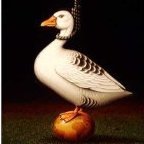
I greatly admire ICM's figures, in particular their range of 1/48 fellows. They are superbly sculpted with convincing drapery and exquisite detailing, and are a joy to paint. This one is one the RAF pilots in the 'Bomber & Torpedo Pilots' set, number 48090 and I painted it to form part of a vignette featuring 2 other figures from that same set (1 slightly modified) and the torpedo also from ICM. I have a wee video about painting this pilot on my YouTube channel, should you be so interested.
- 10 replies
-
- 26
-

-

-

-
I-153 Luftwaffe with Pilots and Ground Personnel (48094) 1:48 ICM via The Hobby Company The I-153 was an interwar creation by designer Nikolai Nikolaevich Polikarpov, and was a sesquiplane, which means that the lower wings were substantially smaller than the uppers, giving the pilot a better view below, and benefitting from retractable landing gear, that gave it a sleeker profile that improved its top speed, the prop driven by a Shvetsov M-62 radial engine. The prototype first flew in summer of 1938, although not with its intended engine, as it wasn’t available at that point in the type’s development. Even with the lower specification engine, it outflew its predecessor the I-15, although once the M62 was installed it proved disappointing with only a small increase in performance. They considered upgrading the power plant, but as it was important not to disrupt or delay production, these changes never reached fruition, making do with the I-153 as it was. While it lacked a top speed that could make it a formidable fighter, it was equipped with four guns that although they were of rifle calibre, they had been re-engineered to increase the rate of fire to around 1,800RPM, effectively increasing the weight of fire to punch above its weight, at the expense of burning through the 2,600 rounds that were carried somewhat faster, giving less than 40 seconds of fire in combat. It first fought in 1939 against the Japanese in Soviet hands, where it acquitted itself well, partly thanks to the manoeuvrability of the biplane, although it wasn’t without problems. The lack of a cockpit firewall meant that an engine fire would quickly penetrate the cockpit area, fanned by a draught that turned the fire into a virtual blow-torch that would leave survivors with terrible burns. The M62 engine was only good for a few sorties before it needed a rebuild, often because of the supercharger breaking down, reducing the availability for combat missions. Various prototypes were built with improvements such as cannons, a pressurised cockpit, and a replacement laminated wooden aft fuselage, none of which went into production, save for a ground-attack variant that carried additional ShKAS machine guns in panniers under the wings, or 20 light-weight bombs, depending on their tasking for the day. Production of the type finished in 1941, but the aircraft continued in service with Soviet, Chinese, and Finnish Air Forces during WWII, and in Luftwaffe service using captured airframes in the usual Nazi style of reusing other people’s gear, despite maintenance and supplies problems. The Kit This is a fresh reboxing of a 2015 tooling by ICM, but with added figures that depict German pilots and ground crew, plus new decals to portray German markings in the service of the Luftwaffe during WWII, which were tooled in 2004. The kit arrives in a top-opening box with a captive lid on the lower tray, and inside are five sprues in grey styrene, a small sprue in clear parts, a decal sheet, and the instruction booklet that is printed on glossy white paper in colour, with profiles of the decal choices on the rear pages. Detail is good on the kit, with a fully-fledged cockpit, engine details, and despite the figures being 20 years old, the detail there is excellent, with crisp sculpting, and moulding that looks as fresh as the first pressing. Construction begins with the fuselage internal framework around the cockpit, which is made from four sections, plus instrument panel with decal, two additional dials on the side frame, assembled and applied over the cockpit floor after installing the seat on two L-shaped brackets, plus rudder pedals and control column on the floor. The completed cockpit is laid in the trough in the centre of the lower wings, which is moulded with both sides having ribbing detail present. Eight holes are drilled out at the ends of the underwing hard-points, putting the assembly aside while the fuselage is made from two halves, adding upper sidewall inserts to each side, and two pressurised bottles low on the fuselage insides, detail painting as per the instructions, then joining the halves, dealing with the seams in your preferred manner. The completed fuselage is lowered over the cockpit in the centre of the wings and glued into position, fitting two thick, aerodynamic interplane struts between the upper and lower wings, the uppers glued to a fairing in the top of the fuselage in front of the cockpit. The elevators are each single parts that slot into the sides of the tail, with their flying surfaces moulded-in. The 9-cylinder M62 engine is moulded as a single part, fitting a star of push-rods to the front with a prop axle in the centre, inserting the detail-painted engine into the front cowling, then adding the intake and exhaust trunking to each cylinder, with a spacer ring in the centre rear. The completed engine is then installed in the forward fuselage, taking care with the exhaust stubs so you don’t bend or break them. Two cowling halves are fixed to the fuselage sides to cover most of the engine, adding an oval exhaust to the lower port side at the rear of the cowling. The two-blade prop has two small triangular parts fitted to the boss, with an optional spinner pushed over the centre to complete it. Another cowling segment covers the top of the engine, and the clear three-pane windscreen is applied over the coaming after fixing a gunsight to it. The main gear bays are moulded into the lower wings, and the struts are built from a single leg with moulded-in jack, adding a retraction jack to the rear, and mounting a single-part wheel to the stub axle at the bottom of each one. A captive door bay is attached to the lower end of the leg after painting, with a pair of inner doors along the centreline between the bays, painted the same colour as the captive doors. The tail-wheel is moulded into its strut, and a pair of V-shaped supports are attached between the fuselage and elevator just forward of the tail-wheel to complete the build. The last diagrams of the instructions show the location of rigging wires in red, which you must make from your preferred material, which you can use in conjunction with your references and the box art to carry out the task to your satisfaction. Figures There are seven figures on the sprue The parts for each one found in separate areas of the sprue for ease of identification, and parts breakdown is sensibly placed along clothing seams or natural breaks to minimise clean-up of the figures once they are built up. The sculpting is typically excellent, as we’ve come to expect from ICM’s artists and tool-makers over the years, with natural poses, drape of clothing and textures appropriate to the parts of the model. There are two officers in flat peaked caps, one in a leather flight jacket and riding jodhpurs over calf-length boots, while the other is wearing a three-quarter leather coat. A pilot in cold-weather gear is being strapped into his parachute by a member of the ground-crew, with two more crew working on the aircraft, one kneeling, the other stood. The final figure is a mechanic standing with one hand on his hip, the other carrying a wooden tool box, while he does nothing much other than spectate. Markings There are three decal options on the included sheet, all wearing German markings in two main schemes. The drawings have diamonds where the swastikas would usually be, as these markings are banned in some territories, and some modellers prefer not to apply them to their models. For those that want to depict their models with historical accuracy however, there are halved swastikas included on the sheet. From the box you can build one of the following: Jagdfliegervorschule 3, Wien-Schwechat, 1942 Luftlandegeschwader 1, Eastern Front, 1942 Reichlin Test Centre, 1942 Decals are by ICM’s usual partners, which is a guarantee of good registration, sharpness and colour density, with a thin gloss carrier film cut close to the printed areas. Conclusion A well-detailed model of this Soviet interwar design, one of the last biplane fighters, depicted in German markings with figures to give it a human scale. Highly recommended. Available from all good model shops now. Review sample courtesy of
-
Panzerwaffe Steel Cats (DS3524) 1:35 ICM via The Hobby Company During WWII Germany’s tanks were both feared and respected by their Allied enemies, although initially the Panzers I and II weren’t particularly technically advanced, they were however an integral part of the Blitzkreig tactic employed by the Nazis during the early days of WWII as they overran France and the Lowlands after taking over Poland, Czechoslovakia and much of Eastern Europe at a similar speed. The Panzer III was more competent, and was in-turn outperformed by the Panzer IV until that encountered the Soviet T-34, which forced upgrades to weapons and armour, and the early entry of the Panzer V and VI into service, which were given the names Panther and Tiger respectively. Never satisfied with big, Hitler was obsessed with bigger, perhaps compensating for something? The almost entirely re-worked Ausf.B variant of the Tiger was given the name King Tiger (KT), Tiger II, or Königstiger, depending on who you ask, but either way, it took the mantle of heaviest tank from the retroactively named Tiger I in the German Panzerwaffe for a while, but without much of an upgrade to the running gear. We can forget the Löwe (Panzer VII), Maus (Panzer VIII), as there is conjecture as to whether the prototypes saw action or not before the end. The Panther is sometimes described as the “best” or most effective tank of WWII, and was available in larger numbers than the KT, although still not enough to change the eventual outcome of the war, sometimes losing out on kudos due to panicked Allied survivors telling the story of being attacked by Tigers. The Set This boxed set includes both a King Tiger and a Panther Ausf.D, and the name is of course a reference to their own naming after big cats. The box contains both kits in separate re-sealable bags in a compact package, arriving in a top-opening box with a captive flap on the inner lid. King Tiger The successor to the much-vaunted Tiger heavy tank instilled more terror in the Allied forces due to initial encounters lending an almost invincible air to the design. It was soon found that although it packed a formidable punch, and could absorb a lot of punishment, it was in fact a flawed design from an engineering standpoint. Further stressing the almost identical transmission even further than the Tiger I, they suffered terrible attrition due to breakdowns, leading to many examples being captured or scuttled by their crew if these breakdowns occurred during combat. When it worked, it was very difficult to kill, and could seriously outrange almost everything on the battlefield, but as with the Tiger I before it, the Allies worked out a strategy to take them out by cooperative attacks between multiple Allied tanks. As well as the reliability issues that were never fully addressed due to the state of the war, the complexity of the design was such that they were never available in sufficient quantities to make a difference, and even when they were, Hitler's obsession with micro-managing every aspect of the war led to some poor placement of resources. Many King Tigers were captured by the Allies and taken back for analysis, with a few remaining intact long enough to find their way into museums, such as the one at Bovington. The Jagdtiger was a development of the King Tiger, using the chassis to mount an even more powerful gun in a casemate, but again very few of these saw action, as it was too late in the war, and they were even heavier than their progenitor. Inside the bag are six sprues and two hull halves in grey styrene, four lengths of flexible black tracks, a decal sheet and the instruction booklet, printed on glossy white paper in colour, predominantly on the rear cover where the profiles are found. Construction begins with the breech, with breech-block, shell ejection guide, the gun mounts and recuperator tubes fitted to create the basics to hold the gun tube. The basic breech is then fitted to the twin slots in the front of the turret floor, and the upper turret gets its mantlet and weather strip glued in place before the two are mated, after adding the roof-mounted vision-block, which is moulded in grey styrene. The two-part gun barrel is outfitted with the studded ring found at its base, and the two-part mantlet ring that sits behind it, protecting the gun and turret front from incoming rounds. Once complete it slots onto the breech, and can be left loose for painting, so you get paint right behind the shield. Next are the commander's cupola and the gunner's hatch, the latter being well-detailed with hand-holds and latches, and the former having a hatch hinge-point protector fitted before installation. Lifting lugs, mushroom vent, shell ejection hatch, periscope armour and the commander's lift-swivel hatch are fitted, with the rear hatch that doubles as the exit route for the gun during maintenance built up with latches and handles, plus the armoured hinges and a representation of the early pistol port moulded in. The delicate mount for the commander's machine gun is fitted to the top of his cupola, and hooks for the spare track links are installed over small marks on the side of the turret, with the links being added from styrene links that are found on the sprues. Now for the hull. There isn't a traditional "tub" for the hull, and you start by building up the sponsons with internal and external parts such as dampers, and the torsion bars for the suspension. The hull floor is a sled that is fitted under the torsion bars that extend across the hull floor. Two perforated ribs are laid front to back on the floor around the torsion bars, stiffening the floor in the process. The engine firewall bulkhead is installed in the rear of the hull along with two plates that are installed under the turret position, with another laid over it that has a cut-out for the turret basket. Two more periscopes are installed in the front of the upper hull, adding a cross-member to the lower hull, clasps to the engine deck, and the armoured kugelblende around the bow-mounted machine gun port, mating the two halves of the hull. The King Tiger was designed with overlapping pairs of road wheels, learning from the mistakes of the Tiger I which had interleaved wheels to spread the vehicle's weight, which could result in taking off up to 14 wheels if an inner one needed repair or maintenance. The all-up weight increased substantially between the two vehicles, so there are a LOT of pairs of wheels on a Königstiger, with nine axles each side, plus the idler and drive sprockets, all of which are assembled from two parts each and fitted to their respective swing-arms. These are capped off with hubs, and later in the build the tracks are wrapped around them. Mudguards are attached to the fenders front and rear, adding towing shackles to the torch-cut eyes nearby, and mounting the final drive housing before installing the drive sprockets. The twin exhausts are made from two halves, and are fixed on the aft bulkhead along with two brackets for the jack, jack block, and a pair of track tools, adding armoured bases to the exhausts to protect the pass-through hole in the bulkhead from incoming rounds. The engine deck has a set of lifting eyes fixed in recesses around the radiator armour, with more around the main engine panel, making up the inspection hatch with two mushroom vents and a grab-handle in the corner before installing it in the rear. The front insert contains two cut-outs for the front crew hatches, both of which have grab-handles, and more lifting eyes for removal during maintenance, gluing it into the forward deck, then adding periscope armour over the top. Pioneer tools, fire extinguisher, mushroom vents and raised frames are added to the engine deck and around the sides of the hull, placing a headlamp on a plinth in the centre of the glacis plate, and towing cables that are moulded with barrel cleaning rods on the sloped left side. The tracks in this edition are of the rubber-band type, each length made from two sections that have overlapping joints that are best glued with super glue (CA) and hidden at the centre of the upper and lower runs to keep them out of your eyeline. Detail on flexible tracks is always a compromise, but the detail is well-done, with only the guides a little simplified. To complete the model, the turret twists into position on the hull using a bayonet connector, adding an aerial to the engine deck at the last gasp to prevent it from being damaged during handling. Markings There are four decal options on the sheet, all with a base coat of dunkelgelb (dark yellow), two with green and red-brown camouflage schemes, one with a coat of winter white distemper that’s beginning to show its age, and one wearing just the base colour. From the box you can build one of the following: Pz.Kpfw.VI Ausf.B, s.Pz.Abt. 509 Feldherrnhalle, Hungary, March 1945 Pz.Kpfw.VI Ausf.B, s.Pz.Abt. 503, Danzig, March 1945 Pz.Kpfw.VI Ausf.B, s.Pz.Abt. 501, Ardennes, December 1944 Pz.Kpfw.VI Ausf.B, Stab/s.Pz.Abt. 501, Ardennes, December 1944 Decals are by ICM’s usual partners, which is a guarantee of good registration, sharpness and colour density, with a thin gloss carrier film cut close to the printed areas. Panther The Panther was Germany's answer to the surprise appearance of the Russian T-34 after they finally reacted to the invasion that was Operation Barbarosa. Although the project had been in gestation for some time before, they took some design cues from the T-34 in the shape of the sloped armour, resulting in the Panther that was intended to fill the gap between the Panzer.IV and the (then) new Panzer VI Tiger. It was eventually supposed to replace both the Pz.IV and the earlier Pz.III that were really showing their age, but in reality it often fought alongside the Panzer IV due to lack of production numbers. It was planned as a lighter, more manoeuvrable tank than the Tiger, and was fitted with a high velocity gun from the outset, which gave it enormous penetrating power that was only equalled by the 17-pounder fitted to the Sherman by the British that turned it into the highly effective Sherman Firefly. The sloped frontal armour gave it an increased effective armour thickness, but this was not quite so true of the side armour, which was weaker and more steeply sloped, becoming the preferred target area of allied tanks, especially in urban combat where this became a telling issue that led to the demise of many Panthers. Like most German tanks of WWII, it was complex and expensive to produce, so suffered in terms of production volume, which led to it being rushed into service with quite a laundry-list of problems still to resolve. Later production solved most of the initial gremlins, but losses in the interim were high with many being abandoned after breaking down during combat. Curiously, the Ausf.D was the first to enter production, with the Ausf.A following later in 1943, replacing attrition of the less reliable Ausf.Ds until they themselves were superseded by the Ausf.G, which became the final major variant, benefitting from increased ammo storage, simplified design to ease production, and further improvements to reliability, although this was never fully cured with a high rate of attrition due to mechanical issues that lingered, some of which resulted in catastrophic fires. There are four sprues and two hull halves in grey styrene, four sprues in black, a decal sheet and instruction booklet that is printed in black and white. Construction begins with the lower hull, which is completed by adding the T-shaped rear bulkhead and the armoured surrounds around the final drive housings at the front of the hull. The many stub axles are inserted into the hull with a peg holding them at the correct angle, and these are accompanied by several additional suspension parts, bumpers, the housings themselves and of course the interleaved main wheels, plus the four-part idler wheels and two-part drive sprockets. The rear bulkhead is detailed with twin exhausts that hold the detailed jack across the armoured bases of the exhaust stacks on two brackets, fitting the uniquely-shaped stowage boxes with separate doors in the top corners of the aft bulkhead. The upper hull has the inside of the glacis plate detailed with driver’s hatch and vision blocks, plus two hatches on pegs that insert into the lift-out front section of the forward deck. The rear deck also has a large inspection hatch in the centre that is decked out with mushroom vents and grab-handles, then has the various rectangular and circular vents from the engine compartment added either side, plus a couple more circular vents and lifting lugs. The stowage for the sides of the hull is made up on frames, one for each side, plus a tube for the barrel-cleaning rods and two racks of spare track links at the rear, again one each side. The separate front mudguards have width indicators added that are fairly unusual for the Panther, then it’s time to make up the tracks. The track links are made up from individual parts that are joined together to create the complete run, although you aren’t given a guide figure of how many to use, but from memory I suspect around 90 would be appropriate. They clip together, but need some glue to retain their integrity, so wrap them around the road wheels while the glue is still flexible, then hold them in place with tape, foam wads and other tools to obtain the correct sag on the return run. The good news is that there are only two sprue gates to deal with per link, but they are on a concave surface, so if you have a circular sanding stick, file or burr for your motor tool, they won’t hold you back for long. There are however two small circular ejector-pin marks in the outriggers of each link’s outer face. Sanding those could be done with a small, flat-tipped burr, or you could make your own and glue some abrasive to it, as I have done in the past. The alternative is to slap some weathering and mud on the tracks to hide any issues you didn’t fix. The turret contains the main gun, which necessitates creation of the holder, which is made from top and bottom halves that are set between D-shaped supports that are glued into the inner mantlet through the turret shell. The outer mantlet is fitted over the top, and the two-part gun tub with moulded-in muzzle-brake slots into the hole in the centre. The rear wall of the turret is first fitted with a circular hatch that attaches via an L-shaped hinge so that it can rotate outside the turret more completely, improving crew access. The shell-ejection port is also fixed on a set of hinges to permit it to swing open if you are careful with the glue, sited on the left turret wall. The turret is completed by mounting the shell on the floor, making up the three-layered commander’s cupola with hatch and pull-ring, adding a mushroom vent near the forward edge, plus smoke grenade launchers, lifting eyes and a grab handle over the rear hatch. It is locked into place on the hull, where two towing eyes and one-part side-skirts are installed, making up a four-part travel-lock for the barrel and mounting it on the forward deck between the front hatches. Markings There are two decal options included on the sheet, although the profiles are both small and printed in greyscale, as you can see below. Both have a base coat of dunkelgelb (dark yellow), with two styles of green camouflage over the entire surface. From the box you can build one of the following: Panther Ausf.D, 52nd Battalion, 29th Armoured Regiment, The Kursk Salient, July 1943 Panther Ausf.D, ‘Grossedeutschland’ Armoured Regiment, August 1943 Decals are by ICM’s usual partners, which is a guarantee of good registration, sharpness and colour density, with a thin gloss carrier film cut close to the printed areas. Conclusion A compact boxed set of two of the most (in)famous German tanks of WWII. Detail is good, although some folks may wish to add some rolled and cast steel texture to the armour. Highly recommended. Available from all good model shops now. Review sample courtesy of
-
 #7/2025 My dad´s next finished one. The ICM Hs126 was first released in 2010, this is the 2015 edition with only Legion Condor markings, also includes bomb racks. Was a tricky build, camo and construction. Plastic was a bit brittle and smaller and thinner parts tended to break already when cutting them off the sprues. All the struts and getting the parasol wing in a more or less correct position was a PITA. The fuselage halves had minimal different length and thickness, the main fuselage to wing struts also slightly different length and the horizontal stabiliser support struts too. Don´t know if the real aircraft had an angled to the left tail, the model has. Added Eduard PE seabelts and used EZ Line for the antenna wires. Painted with AK RC (old ones) RLM/61/62/63/65. Build thread here https://www.britmodeller.com/forums/index.php?/topic/235150826-spanish-civil-war148-henschel-hs126a-1-legion-condor/ Six Hs126 were sent to Spain in late 1938 and served with the 5.A/88 Aufklärungsstaffel of the Legion Condor. They were painted in 61/62/63 and 70/71 camo. DSC_0001 by grimreaper110, auf Flickr DSC_0002 by grimreaper110, auf Flickr DSC_0004 by grimreaper110, auf Flickr DSC_0005 by grimreaper110, auf Flickr DSC_0006 by grimreaper110, auf Flickr DSC_0007 by grimreaper110, auf Flickr DSC_0008 by grimreaper110, auf Flickr DSC_0009 by grimreaper110, auf Flickr DSC_0010 by grimreaper110, auf Flickr DSC_0011 by grimreaper110, auf Flickr DSC_0012 by grimreaper110, auf Flickr DSC_0013 by grimreaper110, auf Flickr DSC_0014 by grimreaper110, auf Flickr DSC_0015 by grimreaper110, auf Flickr DSC_0001 by grimreaper110, auf Flickr DSC_0017 by grimreaper110, auf Flickr DSC_0018 by grimreaper110, auf Flickr DSC_0019 by grimreaper110, auf Flickr DSC_0020 by grimreaper110, auf Flickr DSC_0021 by grimreaper110, auf Flickr DSC_0022 by grimreaper110, auf Flickr DSC_0023 by grimreaper110, auf Flickr DSC_0024 by grimreaper110, auf Flickr Parasol wings united.....one could think they are in different scales DSC_0025 by grimreaper110, auf Flickr DSC_0026 by grimreaper110, auf Flickr
- 14 replies
-
- 46
-
-
-

-

ICM Luftwaffe Airfield Equipment (48409) 1:48
Mike posted a topic in Aftermarket (updates/conversions)
Luftwaffe Airfield Equipment (48409) 1:48 ICM via The Hobby Company Any airfield that is hosting a squadron or more of aircraft, whether it is bombers, fighters, reconnaissance aircraft, or other more minor types, a great deal of equipment, tools and supplies are required to keep them operational. During WWII, the Luftwaffe undertook many campaigns against enemy states, usually in a bid to assist with their invasion of that state, but toward the end of the war they were fighting furiously for the existence of their ‘Fatherland’, and the future of the Third Reich in Germany. Re-arming and refuelling were key tasks, replenishing the magazines of defensive or offensive armaments, such as machine guns and cannons, or bombing-up the bombers that went from bombing other countries mercilessly to making comparatively short sorties to the front line to rain death and destruction on the ever-advancing Allies until the Luftwaffe was a spent force, bereft of crew, fuel and at times aircraft too. This new set from ICM arrives in a shallow top-opening box with the usual captive flap on the lower tray, and inside are nine sprues of grey styrene, two decal sheets, and the instruction booklet that is printed in colour on glossy white paper. It incorporates a stack of bombs of various sizes, as follows: 8 x SC 50Jb bomb 4 x SC 250Ja Bomb 4 x SC 500J 8 x SD 50Stg 4 x SD 250Jb 4 x SD 500A It also contains parts for a bomb trolley that is used around the airfield to move bombs, and can be raised to secure the weapon under the aircraft once it arrives at the aircraft. The bomb cradle is made from two halves with a central lever, while the two arms of the Y-shaped trolley are each made from two parts that trap a single wheel at the rear end. The two arms are brought together around the cradle, adding a two-part jack on the top, and a third wheel with castor mount and towing T-bar underneath, fitting a curved cross-brace under the centre of the frame between the twin arms. A tripod crane is made from a three-part set of pulleys with a chain link, which is suspended by three legs over the ground, one of which has steps welded across to permit a worker to climb to the top if necessary. A set of three each of 50kg and 250kg bomb crates can be made from six parts each, with wooden planking engraved in the surfaces along with handles and strengthening braces, along with three Jerry cans with separate triple handles and filler caps, three fuel barrels with separate end caps, and a pressurised bottle on a two-wheeled trolley with upper pull-handle that also protects the regulator, A tool box, spray gun, short stepladder, and a large oil barrel. In addition, a guard booth is made along with a barrier, a combination that is seen wherever security is higher than the surrounds, and this comes with chevron decals to lay over the planked wooden surface. Markings Two separate decal sheets are included, one from the bomb set that was released earlier, and another new sheet that includes decals for the guard booth and barrier, plus the many bomb crates, which are festooned with stencils. Even the tool box has two stencils applied to the side and end, while the bomb cradle, bottle and crane have none. Decals are by ICM’s usual partners, which is a guarantee of good registration, sharpness and colour density, with a thin gloss carrier film cut close to the printed areas. Conclusion A great deal of detail is supplied in this set to benefit anyone considering a diorama or vignette, or just wishes to place some additional equipment near their Luftwaffe aircraft in the cabinet. Highly recommended. Available from all good model shops now. Review sample courtesy of -
Here is my little creature which I've finished in 5 days during our regular "Build & Chat" session last week. ICM's kit builds with no problem. I've replaced the landing gear legs with the excelent Aerocraft set. Some PE from Eduard is used in the cockpit. Decals are from AOA "FAC & BS BOMBER OSCAR DEUCES". The conversion parts for O-2B (loudspeaker and leaflet dispenser) are my own 3D construction and print.
- 13 replies
-
- 58
-
-
-
-
Before the Assault – Eastern Ukraine 2022 (DS3521) 1:35 ICM via the Hobby Company In February 2022 an unlawful and unprovoked invasion was started by a foreign aggressor on the Eastern border of Ukraine, causing years of upset, distress, death and destruction in an innocent country and its people, not to mention the carnage inflicted on their own poorly equipped and trained soldiers in the process. Ukraine’s steadfast and determined resistance has been inspiring to many, and support has been forthcoming from Allies around the world, most of whom expect nothing in return other than friendship, as supporting a sovereign Nation during a criminal invasion by a dictator shouldn’t be a case of “what’s in it for me”. There’s such a thing as a moral compass, or should be. The Kozak Mine Resistant Ambush Protected (MRAP) vehicle was developed in response to a need for protected troop transports for reconnaissance, patrolling and other such tasks, and was first seen in 2014, although only a few proof-of-concept vehicles were made by Practika, in competition with several other types from other manufacturers, the Kozak going through to the next stage as one of the three that met the Ukrainian Army’s requirements. The original vehicle is based upon a heavily modified Iveco Eurocargo chassis, but this 2015 design is based on the Iveco Daily, which has a shorter chassis, resulting in a more compact vehicle. Looking at any of the variants side-by-side you wouldn’t think they were related to anything, as the outward differences are so great. It doesn’t have a sharply V-shaped hull in the same respect that custom designs do, but most of the chassis length is protected by a shallower V-shaped armoured panel that underpins the crew compartment, and in concert with the anti-trauma seating that is installed within, it satisfies the needs of the Ukrainian forces in the event of an IED detonating underneath. The exposed wheel stations would probably be sacrificed in the blast, but the diversion of the explosive energy away from the crew is the key aspect. After the initial design, the improved Kozak-2 was engineered, incorporating a weapons station on the roof that allows the operator protection from small-arms fire, with vision slots that are protected by armoured glass in each of the side wall panels, plus a splinter-guard with more vision slots at the front, through which the machine gun projects, which can either mount an NSV heavy machine gun, or a 7.62mm weapon, depending on availability and mission requirements. The Kozak-2 entered service in 2017, and has seen plenty of active service since the unlawful invasion of Ukraine that began on 24th of February 2022. The Kit This is a reboxing of the recently tooled Kozak-2 by ICM, and was designed in cooperation with the vehicle’s manufacturers Practika, as noted on the original box top, which bodes well. The kit arrives in a top-opening box, with a captive flap on the lower tray, and inside are seven sprues of grey styrene and nine figure sprues in grey, two identical clear sprues, a bag containing five flexible black plastic tyres, a small fret of Photo-Etch (PE) of a copper-coloured metal, three decal sheets, and the three instruction booklets that are printed in colour on glossy paper, and have profiles on the rear pages to help with painting and decaling. Detail is excellent, and as it’s a home-grown product, local knowledge will have come in very handy, as will their nearness for detail checking, although the vehicles have been rather busy of late, working tirelessly to recover parts of their country still occupied by the invader. Construction begins with the chassis rails, which have a leaf-spring attached to the front, and two double-leaf arrangements that are each made from two halves at the rear. Small armour plates and other parts are fitted to the frontmost sides, then the cross-members are built up, with two under the engine bay, a central four-part transfer box at the midpoint, a tough braced bar behind that, and another at the rear. Under the rear suspension is an additional cross-rail, plus a braced rail that has a pair of two-part tanks applied, one on each side before mounting. The solid floor pan is detailed with a three-part representation of the underside of the engine and sump, then the chassis rails are mated to the underside on tabs, adding a short drive-shaft that links the transmission to the transfer box, ready for when the axles are completed. The front axle is a thick assembly with differential bulge in the centre, which is made from two halves, and has the rear of the hub attached at the ends, and a damper bar that joins to the chassis via links, and the drive-shaft that links it to the transfer box. A steering actuator and two armoured plates are fitted over the newly mounted axle, adding two dampers to the rear, and a C-shaped linkage that joins the two hubs together. The rear axle is built from four parts, and is much bulkier than the front, as are the hub assemblies, which are each four parts. This is then glued to the leaf-springs, adding dampers, drive-shaft, damper bar, another cross-member and a towing shackle at the rear. The interior of the Kozak-2, which if you haven’t already guessed means ‘Cossack’, is a spartan compartment that is designed for a purpose and nothing more, keeping weight and clutter to a minimum, as well as reducing the likelihood of small parts becoming missiles in the event of an IED detonation. The crew seats are made first, making the back from cushion and backrest, then adding this to the base cushion and two concertina-style side panels, plus front and rear sections, taking care to line up the concertina elements to minimise clean-up. An adjustment lever is fixed under the front edge, and you should bear in mind that the seats are handed, so take care to fix the correct one to the tread-plated floor on its guide-slots. A small gear lever is made from two halves and inserted into the centre console, which is moulded into the floor. The dash is a single moulding that has the three foot pedals glued into the lower portion, then has the multi-part steering wheel, column and separate stalks fitted on the left side, with a gaiter and hi/low ratio knob mounted in the centre of the dash low down. There are three decals for the dials and controls on one of the sheets, but remember to paint the instrument binnacle black before you put the decal on. The dash is mounted on a central locating guide in front of the crew seats, and behind and between them a four-part rack with crew step/jump seat that has anti-slip tread-plate moulded into it, and acts as the support for the gunner when he is in action, folding away when not in use to keep obstruction to a minimum. For an in-action pose, the supplementary instructions show the alternative layout of those parts to give the gunner a platform to stand on. Two passenger seats are built with two-part backs, adding safety tubing to the sides and top that helps prevent flail and neck injuries, fixing onto the seat cushion that has more U-shaped tubes glued underneath that project up and help keep the sitter’s body in position in case of a sharp sideways jolt. A back frame and a pair of shock-absorbing tubes attach the frame to the deck behind the driving crew, facing forward. The other six seats are fitted centrally with three on each side facing left and right. The base cushions are all moulded as a single linked unit, to which the lower tubes are fitted, adding two central supports in the space between them, then adding the backs, which are built at the same time as the first pair. This assembly is then mounted on a pair of raised rectangular areas of the floor, ready for the body to be built up. The vehicle sides are one part each, and cover the entire length of the chassis, adding radiused bullet-proof windows in the sides, a foot-plate at the front, and drilling out four 1mm holes as indicated in a scrap diagram nearby. An interior skin is prepared by adding grab-handles and weapon stowage clips under the windows, with the inner face of the shooting loupes moulded into the surface. The laminated right side is offered up to the chassis, adding the front wing liner and inner panel to the engine bay at the same time, then doing the same for the left side, before working on the windscreen panel, which has two panes inserted into the frames, and two instruments applied to the centre frame on the inside. This is mated to the bonnet and two windscreen wiper blades are fitted into pockets in the bonnet before joining the two. The rear bulkhead has an inner and outer skin, then has the multi-part bumper and clear light clusters applied to the lower edge. It would be a good idea to prepare the front and rear panels at the same time as the sides, not just for ease of painting, but also to ensure that the side panels are mounted to the correct angle and can’t sag while the glue cures. The roof has four small parts fitted to the underside before it is glued in place, completed with a pair of moulded-in escape hatches and the circular cut-out for the roof-mounted weapons station. The grille is fitted to the front of the vehicle, and has a thick bumper with moulded-in reflectors for the clear lights that are installed and painted with suitable clear shades, then have protective cages folded from PE parts, with a winch housing between them. The front skirt is made from two layers and has small sensors fitted into recesses, then is assembled on the front with the bumper, and a cow-catcher that is built from eight parts, including three slats that protect the grille. The Kozak-2 has four side doors, two on each side, all of which have inner and outer skins plus glazing, with grab handles fitted inside, and handles on the outside, while the front doors have wing mirrors on C-shaped tubular frames, and the rear doors have a circular cut-out that doubles as firing loupe for the front passengers. The back doors are similar in construction, but with a smaller fixed window near the top, inserting into the frames at the rear. All doors can be mounted open or closed as you please. Inverting the model allows fitting of the shallow anti-mine keel panel, which has the ends closed off to prevent ingress of the explosive wavefront, which would reduce its effectiveness. Mudflaps are added to the rear of the front wheels, and on both sides of the rear wheels, then the wheels are made to fill the arches. The spare tyre is built first, adding a two-part hub from either side of the flexible tyres, and mounting it under the body at the rear. The rear pair of wheels have a slightly different pair of hub halves inserted from each side, and then have a choice of two styles of dust covers fixed over the outer face. The front wheels have similar two-part hubs, with an additional centre insert, and the same choice of dust covers over the front. They all fit onto their appropriate axles, but don’t put the model on its wheels just yet. There are a pair of crew steps to be fitted onto the keel panels under the rearmost side door on both sides, then the model is turned right-side up for all the external detail to be added to it. The first item is a searchlight, which has a clear lens and opaque rear, mounting on the right wing in front of a small part near the scuttle. A perforated mount for the pioneer tools is filled with four hand-tools before it is mounted on the right rear of the body. A two-part cage is closed around the searchlight, and completed by adding two top bars, and a bracket that stands out past the side of the wing for another mirror that is added later. Under the tools a pair of three-part brackets are mounted on recesses, and on the opposite side a pair of towing arms are fitted under the windows on pins. Two small lifting eyes are glued to the scuttle, and an LED lamp with armoured shroud fits into a pair of recesses on the left wing. What looks like a tubular convoy light in a shroud is added to the centre above the rear doors, and five rungs are glued to the left side of the rear for access to the roof, with a sixth on a bracket that hangs down below the bodywork, adding a jerrycan in its holder to the left. Grab handles are fitted between and above the side doors, on the roof above the ladder, and on the front and sides of the bonnet to ease access to all the horizontal panels, and on the right flank, a cage is fixed to the body for additional storage. The detailing is still far from over though, as the wing-mounted indicators and roof-line repeaters are positioned, with the more exposed lower wing lights protected by four half-torus PE guards that create a cage around them on both sides. PE cages are added around the rear lights too, bending the ends to match the profile, then adding a pair of stirrups below the back doors. A plate is glued to the left door frame to accept a two-part exhaust that allows the vehicle to plough through water up to a metre deep without stopping to prepare. The right door frame has another assembly made up from five parts, which looks like an emergency flasher, but clearly isn’t. The machine gun turret has a pair of smoke grenade launcher assemblies made up with three barrels each on a carrier plate that is fitted to the front corners of the assembly. The two side armour panels have their bullet-proof vision panels inserted from inside, and are then assembled onto the base, which has a circular ring with bayonet lugs fixed to the underside, and moulded-in stiffeners on the top surface to keep the armour at the correct angle, even under fire. The D-shaped crew hatch is given a pair of handles, and is then fixed into position in the turret floor in the open or closed position as explained in the supplementary instructions, adding an A-frame mount for the machine gun, which needs a 1.2mm hole drilling to accept the weapon, which is built up from a breech with moulded-in barrel that is clamped between two mounting halves, with handle added to the rear and ammo feed on the top, linked to a three-part ammo box as it is slipped into the splinter shield, which also has two vision blocks inserted from within. The completed gun is then lowered onto the mount, securing its pin into the hole drilled earlier, then finishing off by adding a rear-view mirror on a U-bracket, a hand-traverse wheel on the underside, and a wire across the back of the turret. The completed assembly then drops into the cut-out and is rotated to lock it in place. Markings There are four options on the decal sheet, all with a base coat of green, and various digital camouflages applied over the top. From the box you can build one of the following: KOZAK-2, 35th Separate Marine Brigade of Ukraine, January 2021 KOZAK-2, 36th Separate Marine Brigade of Ukraine, August 2021 KOZAK-2, reconnaissance unit of the Armed Forces of Ukraine, November 2022 KOZAK-2, an unknown unit of the Armed Forces of Ukraine, autumn 2022 <ul style="list-style-type:upper-alpha"> Decals are by ICM’s usual partners, which is a guarantee of good registration, sharpness and colour density, with a thin gloss carrier film cut close to the printed areas. Ukrainian Special Forces (35752) Ukrainian Special Forces, are highly-trained soldiers that get up to all sorts of mischief and have the best equipment available to do the most damage to the invader. They infiltrate, do their work then exfiltrate, hopefully without being seen or heard unless they want it that way, but if they become engaged with enemy soldiers, they are well-armed and trained to look after themselves, returning home to base for the Ukrainian equivalent of tea and scones, followed by some rest, before going out another day on the next mission until the country is totally free. True bravery. There are four figures in the set, representing a squad of soldiers that are discussing their next move around their leader, but with weapons ready in their hands in case they are seen by the enemy. Two soldiers are stood looking down at their commander’s handheld device, while he and the other team member are crouching down. The parts for each figure are found in separate areas of the sprue for ease of identification, and parts breakdown is sensibly placed along clothing seams or natural breaks to minimise clean-up of the figures once they are built up. The sculpting is typically excellent as we’ve come to expect from ICM’s artists and tool-makers, with natural poses, drape of clothing and textures appropriate to the parts of the model, especially the tactical vests, which are covered in MOLLE loops to hang their gear from. If you’re not a big fan of painting faces, all the troops have masks over their mouth and nose, partly for anonymity, but also to keep out the dirt and dust kicked up during combat. The accessories are on two identical smaller sprues that contain several AK74 derivatives, with a choice of different stocks, an underslung grenade launcher, and even the locally produced AK-based bullpup the Malyuk, which means baby, but it also has a more aggressive name of Vulcan-M. If you look closely, you can just about see the AK bones beneath the rifle’s skin. A light machine gun is also included, the Ukrainian variant of the PKM, which is known as the KT-7.62 that is manufactured by Mayak. One edge of each sprue has a pair of FAST helmets that are often used by Special Forces, and have side rails plus a separate night vision goggle mount on the front. The last few parts are a couple of pistols in paddle-holsters, knives in and out of scabbards, optics for the weapons, and comms headset cans (probably Peltor) that are shown on the drawings, but don’t have their part numbers mentioned, but for reference purposes are parts W12 + 13. A driver figure has been culled from another set, and is provided with cushions that are compressed under his weight, wearing similar equipment as that of his colleagues, but with his hands gripping the steering wheel, and feet on the pedals to control the vehicles. Drone Operators Two figures have been taken from the recent “War Has No Gender” figure set, one soldier stood launching a drone from one hand, while the other is controlling a drone on a remote with legs crossed in front of her as she sits on the ground concentrating on the task in hand, with a stack of gear and another drone accompanying them. Both figures are wearing modern BDU pants, with a plate-carrier or tac-vest that carries magazines and other pouches, the drone fliers wearing peaked caps to keep the sun out of their eyes, plus a pistol on a drop-leg holster for protection. Gunner & Observer Two new figures are included in this boxing, each on a separate small sprue along with their relevant equipment and gear. One member is operating the roof-mounted gun on the Kozak-2 with his arms out gripping the gun, wearing similar gear to the other figures, but with an extension on his plate cover that protects his groin area, as he would be a high-value target when engaged in combat. The other figure is standing looking through a pair of binoculars into the distance, with a weapon slung at his front, and a large medical pouch on his hip. The rest of his equipment is similar to the rest of the crew. Figure Painting Modern Ukrainian troops frequently wear Multicam or digital pattern BDUs and equipment, a swatch of both are shown on the painting guide, although solid green is also an option, however Multicam is much more Gucci, and is an effective camouflage in all areas of operation except arctic. The instruction sheet has drawings on the back of the sprue guide, which has red letters in boxes that correspond to the table overleaf giving colour names, plus the codes from ICM’s own range of paints, most of which can be found in boxed set 3041. You can find details of that set along with many others in our mega-review here. If you’re worried about painting camouflage colours, there are decal sheets available now that can make the task a lot easier, using zenithal highlighting with white on a darker primer before applying the decals, then using washes over the decals once set to deepen the darker folds. Conclusion With the addition of a suitable base, this new set will make a great subject for a diorama, with plenty of figures to give it a human scale. Detail is good, and there are four good decal choices on large sheets to keep you busy modelling. Highly recommended. Available now from all good model shops. Review sample courtesy of
-
Typ 320 (W142) Cabriolet B (35543) 1:35 ICM via H G Hannants Ltd In the 30s, Mercedes replaced their 290 chassis with the longer 320 in 1937, offering a standard or longer chassis variant, the latter being the basis for the top-of-the-range Cabriolet body format. The extra length gave the vehicle a sleeker, more sporty appearance, which coupled with a raked radiator grille, lack of light bar, and the canvas roof made it all the more streamlined in appearance. Under the bonnet was a 3.2 litre straight-six side-valved petrol engine that produced 78hp and a top speed over 120km/h or 75mph. Power was delivered via a four-speed manual gearbox with synchromesh on all forward gears, which was a luxury at the time. In military service as a staff car, the 320 was fitted with a shrouded convoy light on the left wing, and could also have a short mast on the same wing to display the occupant’s allegiances, battalion etc., with a spare tyre on both sides, which was a common fitment even in civilian service. In 1938 an updated model was introduced, with displacement bored out to 3.4 litres and adding overdrive to shorten the journey to top speed, although the documented HP wasn’t increased, possibly due to de-tuning of the engine to accommodate inferior fuel quality that was beginning to become a necessity as Germany geared up for war. The Kit This is a reboxing of a partial retool that was based upon the hard-top version released by ICM in 2016, depicted with a retracted hood that when deployed keeps the passengers safe from precipitation or cold. It arrives in a top-opening box with the usual captive lid on the lower tray, and inside are two large sprues and a smaller one in grey styrene, three pairs of black flexible tyres on small sprues, a clear sprue, decal sheet, and instruction booklet, where you’ll find the decals tucked away. The instructions are printed on glossy paper in colour, with profiles on the rear pages to help with painting and decaling. Detail is excellent, and extends to a full engine and transmission, plus a very crisp interior, as well as a very natural depiction of the stowed roof. Construction begins with the engine, the block and transmission being made from two halves with the sump and cylinder head added from above and below. The air box and exhaust manifold along with the down pipe are made and attached to the right side of the motor, adding the dynamo and other ancillaries to the left side, the serpentine belts and pulleys to the front with the fan, and more hoses and the distributor pot on the top. The chassis rails are each made from two parts to achieve the correct length, adding short outriggers to the outsides, and a large cross-member at the rear of the chassis that holds the rails in the correct tapering attitude, as well as having moulded-in details of the rear differential on the lower side. Two more cross-members support the frame, adding the differential, axle and drive-shaft down the centreline, and the front suspension arms with their leaf-spring and coils, plus twin coils and other parts installed over the top of the rear axle. The rear wheels are created by inserting the two sides of the hubs into the holes in the tyres so they can be slipped onto the ends of the axles, adding a two-part fuel tank in the rear at the same time. The motor and bumper are fixed in the front, and joined by a pair of wing supports and the radiator, which plugs into the pipes leading to and from the engine, then the floor pan can be lowered onto the chassis, including the rear panel below the boot in-between the moulded-in rear wings. Before turning the vehicle right-side-up, the single part exhaust and two mufflers are inserted, attaching to the end of the down pipe and a tab just in front of the rear axle. Inside the cab, the pedals, gear lever and hand brake are all installed in the left footwell and transmission tunnel, followed by the firewall that has the windscreen frame moulded-in, fitting the two-pane glazing and the dashboard before it is inserted into the space between the cab and engine bay, adding a few knobs and a binnacle decal before you do. A dash pot is popped into the engine side of the firewall, and the long steering column is threaded through into the cab with the lower end buried deep in the engine bay. Both front and rear seats are bench-type, and their bottom cushions are each made from a main part with a rear edge that has a recess to accommodate the transmission tunnel moulded-in, fitting into the cab on paired pegs at both ends, and they are joined by the rear cushions that have their backs glued into place before fitting. The body sides are next, inserting door cards with handles and winders before they are latched on pegs to the floor pan, fitting the boot panel and a two-part steering wheel, then the radiator grille that is stabilised by an X-brace that fits into holes in the firewall. The side windows front and rear attach to the sides via pegs, and the bonnet covers the engine, but with a bit of surgery it could be posed open. The two spare tyres are made in a similar three-part arrangement as the others, and are locked in place in recesses in the front wings by brackets running between the tyres and body. The windscreen has a rear-view mirror and two sun visors fitted to the top interior, and two wiper arms are added to holes in the outside near the centre of each pane at the bottom, dotting lights, handles, and indicators around the front of the vehicle as appropriate, including a three-pointed star motif on the top of the radiator. At the rear are tiny light clusters and twin handles for the boot, fixing the rear bumper to the rear panel. The folded canvas hood is made two main parts plus two side sections that are moulded with creases and folds for realism, adding the metal outer framework after it is glued to the back of the vehicle. Markings There are four decal options and you’d be forgiven for thinking any colour as long as it’s black, but you’d be wrong, because there are some stylish colour options, and of course you can choose any colour you like for these civilian cars. From the box you can build one of the following: Province of Brandenburg, Late 1930s Province of Hanover, Late 1930s State District Upper Bavaria, Late 1930s Berlin, Late 1930s Decals are by ICM’s usual partners, which is a guarantee of good registration, sharpness and colour density, with a thin gloss carrier film cut close to the printed areas. Conclusion A sleek Merc for the transport of the well-heeled civilian around the countryside, with plenty of detail that should allow a realistic replica of the type to be made. Highly recommended. Available in the UK from importers H G Hannants Ltd. Review sample courtesy of
-
My second entry to the GB will be the ICM North American Rockwell OV-10A Bronco. Quite a new kit and looks nice. Never build an ICM aircraft before, so should be fun. Sprue shots Then these two are identical. Loads of ordnance! Decals, masks and some detail for the cockpit. Only 2 weeks to go! Roll on the 15th! George
- 19 replies
-
- 12
-
-
My 2nd build of the year and a bit rushed. Always had a fascination for this beast of an aircraft so that's another itch scratched. A good kit though I struggled with fitting the cockpit canopies and it shows! Also had to resort to surgery to fit the front and rear fuselage sections together, but the butchery is invisible in the finished model. Finished with Tamiya acrylics (flat aluminium). Not strictly in line with the kit details but seems right for this Soviet era aircraft.
-
2cm FlaK38 with Crew (35718) 1:35 ICM via H G Hannants Ltd Starting life as a 20mm naval anti-aircraft gun that was developed into the FlaK 30, the FlaK 38 was a further development of the basic gun to improve the fire rate that had previously been less than inspiring. The improvement meant an increase from 120RPM to 220RPM, but also benefitted from a decrease in all-up weight, which eased its way into service with the army in late 1939, just in time for WWII. As well as the usual trailer mount and three-legged base, a lightened mounting was also created for the gun, using a tripod that reduced the weight still more, and made it air-transportable by paratroopers into active warzones. Following accelerated acceptance trials, the new design began service with the Wehrmacht and Luftwaffe in the summer of 1940, where it became the standard light-weight Flak defence weapon for close-range operation, where it was highly effective. Crews also found that the weapon was devastating against personnel and lightly armoured ground targets, which it could attack due to its wide range of elevation. This led to it being mounted on the back of trucks, half-tracks and other armoured vehicles where it could perform both roles, which it continued to do until the end of the war. It was considered less effective by the RLM later in the war due to the increasingly well-armoured fighters it was ranged against however, and in addition to being fielded in Zwilling (twin) mounts, it was also used in a quad-mount for increased fire density, with the intention of replacing it with a 40mm gun if the war had lasted longer. The Kit This is a reboxing of a brand-new tooling from our friends at ICM, and although many other companies have their own FlaK 38s in 1:35, this is their offering, and it’s a fresh tooling that has been created using accurate dimensions and proportions in an effort to obtain a highly realistic rendition of this important German anti-aircraft gun. The kit arrives in a shallow top-opening box with a captive flap on the lower tray, and inside are three sprues of grey styrene, a small decal sheet and instruction booklet printed in colour on glossy paper, with painting and decaling profiles on the rear pages. Construction begins by trapping the gun barrel with moulded-in breech between the two halves of the cradle, sliding the assembly into the armoured mantlet if you are building the variant with a splinter shield, with two L-shaped supports holding the cradle to the mantlet. Two hollow circular pivots fit on the sides of the cradle, slotting a magazine into the breech on the left side through the hole, and these locate in a two-layer trunnion on each side, choosing which elevation piston to fit underneath to set the barrel for anti-aircraft or travel and anti-personnel operations. The trunnions locate in slots on a circular base that has tread-plate moulded into the sides, fitting elevation and rotation mechanisms to the right and at the rear of the trunnions. The sighting gear is mounted on an arm above the rear of the gun, and a pair of seats are built and installed, one on each side over the tread-plated areas. The option with the splinter shield has a horizontal support tube fitted on two brackets at the front under the barrel, mounting two sections of shielding on the bottom tube, adding upper brackets to steady the parts during firing and transport. Two small tabs are removed from the circular pivots if you are fitting the shield, and an additional shield is fitted on a bracket in front of the gunner’s position, which is raised above the main shield for sighting the gun. Three additional magazines are supplied to store in the ready-mag box on the left side of the gun for either variant. The base consists of two layers with a large circular cut-out in the centre, plus three feet, one on each outrigger, lowering the completed gun into position as the final part of the build. A pair of diagrams show the completed model in armoured and unarmoured finishes to assist you with making your choice and ensuring you build it using the correct parts. The Figures The figures are newly tooled specifically for this boxing, and are found on a single large sprue of grey styrene. The parts for each figure are found in separate areas of the sprue for ease of identification, and parts breakdown is sensibly placed along clothing seams or natural breaks to minimise clean-up of the figures once they are built up. The sculpting is typically excellent, as we’ve come to expect from ICM’s artists and tool-makers, with natural poses, drape of clothing and textures appropriate to the parts of the model. Three figures are standing, one pointing to the sky with binoculars in his hand, spotting a target for their attention. Another figure is resting a foot on part of the structure, looking skyward and following the direction the spotter is pointing. The third standing figure is using a wide-set binocular sight to get a range on the target, while the seated figure is operating the gun with his feet and hands on the controls, also looking skyward. The range-finder can be found on one of the other sprues as part A11, and it has a detailed painting guide amongst the figure drawings that act as both instructions and painting guide, having part numbers and colour codes that correspond with a table on the front of the instructions that give ICM’s colour codes for their range of acrylic paints. Markings There are two decal options for the Flak38, both wearing camouflage of various colours. From the box you can build one of the following: Italy, 1943 Western Ukraine, 1944 Decals are by ICM’s usual partners, which is a guarantee of good registration, sharpness and colour density, with a thin gloss carrier film cut close to the printed areas. Conclusion An artillery piece, whether its target is on the ground or in the air, always has more presence when it is crewed, as it gives the model function as well as the oft-mentioned human scale. Detail is excellent, and should build into an impressive model with some care and attention. Highly recommended. Available in the UK from importers H G Hannants Ltd. Review sample courtesy of
-
 Hey all, This is ICM's new-ish A-26 Invader. The A-26 has always kind of appealed to me as a mean looking aircraft that always has a presence, even on the ground. When ICM announced they were releasing one I immediately knew I must get one, but its not until earlier this year that I took the plunge. The kit is beautiful out of the box, and went together nearly as nicely as a Tamiya kit, requiring minimal filling, sanding or other adjustments. As a rather expensive kit however, it would've been nice to complement the kit with some PE, especially belts, but this isn't a deal-breaker for me at all, and I simply used a generic USAAF/USN seatbelt set from Eduard. The kit was painted using a mix of Tamiya Lacquers and Mr. Color acrylics, then weathered with oils, acrylics and a few pigments. The decals OOB were a bit fragile and required careful handling, but there were a number of interesting schemes available right out of the box. Overall, an enjoyable build of a surprisingly large aircraft that certainly has a presence on my display shelf. Thanks for looking, Sam Again, thanks for looking, Sam
 -
Feldküche – Field Kitchen with Cooks (35618) 1:35 ICM via H G Hannants Ltd The idiom “an army marches on its stomach” was attributed to Napolean amongst others over the centuries, and its meaning is that without food, an army will be unable to advance after a relatively short period of time, a situation that Napoleon’s army found themselves in when they invaded Russia in 1812. Sustenance is crucial for the ongoing wellness of any person, and for a soldier that is expected to fight when they reach their destination, it is doubly important. With the industrialisation of warfare, the provision of food to keep soldiers fit, healthy and ready to fight was similarly modernised, creating “field kitchens” that were highly mobile, and could be set up quickly at any sensible location, often a field as the name suggests. Once halted, the wood-fired ovens were lit, and a meal was either cooked from scratch or pre-prepared repasts such as stews or soup could be warmed up for expediency and to keep the soldiers warm during winter campaigns. Germany’s WWII Feldküche was sometimes referred to as the Gulaschkanone, due to the way in which its chimney folded horizontally for transport, giving it the look of an artillery piece from some angles if you squinted. The Kit The main sprues of this kit were seen earlier in a boxing that came with a truck to transport the kitchen, so while ICM’s statement of being 100% new tooling might be slightly optimistic, the main sprues are only a couple of months old. It has now been re-released without a vehicle, but with a set of figures to cook up the food for the soldiers, and it arrives in a shallow top-opening box with a captive flap on the lower tray. Inside are four sprues, although in this boxing the two outriggers of one of the sprues have been nipped off in order to fit within the smaller box. A decal sheet and instruction booklet complete the package, printed in colour with profiles on the rear pages for the two decal options. Detail is good, and as usual ICM’s figures are excellent, with realistic poses and sensible parts breakdown. Construction begins with the body of the kitchen that has a large circular cooking area for mixing and keeping the Goulash warm, which is first evidenced by a circular depression in the floor, fitting the rear of the box to it, then adding the sides, and an internal divide, finishing off with the front of the body. The top has a raised edge to a circular cut-out, and this has a large pan with curved bottom edges glued underneath before it too is fitted to the top of the body, creating two raised areas by doing so, which have their own tops that have bases of other storage areas, adding the lids to each one and the central circular lid to keep the goulash warm. The chimney is made from two halves, with a rib around the lower end that shows where it folds, but it is moulded as one length for this boxing at least. It mates to the top of the kitchen on a raised rim, then work begins on the kitchen’s chassis, which is more akin to that of a horse-drawn carriage, which is appropriate, as it was sometimes pulled by horses when vehicles weren’t available. The axle is fitted to the leaf-springs moulded into the curved chassis rails, adding a cross-brace and triangular web toward the towing eye. The finished frame is then glued under the body of the kitchen, fitting three covers to vents under the fireboxes, one having a short ladder that could be folded down or out to add extra working space, or to hang cloths to dry next to the warm ovens. Two one-piece cart wheels are fitted to the ends of the axle, fixing a front rail under the kitchen, which has a V-shaped support to add strength. The final part is a support pole that is used to keep the kitchen level when unhitched, stopping the whole thing from pitching forward due to the weight of the A-frame, or back due to the weight of the goulash. There are several accessories to be made that can be used to create a scene around the kitchen, which includes a metal jug with conical top; two jerry cans with prototypical triple handles; two buckets with separate handles; two wooden crates made from six parts each; four large sacks, six smaller sacks of ingredients with tied tops, and four oval metal storage containers with separate lids. Figures The new sprue contains parts for four figures, consisting of a standing chef, a seated potato-peeler, a man chopping wood on a stump to fuel the fire, and a final figure bringing a Jerry can of water to use during cooking. The parts for each figure are found in separate areas of the sprue for ease of identification, and parts breakdown is sensibly placed along clothing seams or natural breaks to minimise clean-up of the figures once they are built up. The sculpting is typically excellent, as we’ve come to expect from ICM’s artists and tool-makers, with natural poses, drape of clothing and textures appropriate to the parts of the model. Various accessories are included on the sprue, from open bags of potatoes, logs of various sizes for the axeman to chop, a work table, cutting board and several sausages ready for chopping by the chef’s moulded-in knife. He also wears a chef’s hat and apron in case anyone wondered. Markings There are two colour options as you might already expect, either early war Panzer Grey, or later war Dark Yellow (Dunkelgelb). The decals include stencils for the kitchen, and the accessories, plus battalion markings, and on the grey option, a little nose art on the sides of the kitchen. From the box you can build one of the following: Pre-1943 Colour Scheme Post-1943 Colour Scheme Decals are by ICM’s usual partners, which is a guarantee of good registration, sharpness and colour density, with a thin gloss carrier film cut close to the printed areas. Conclusion A field kitchen without figures is simply a piece of equipment. Once you add figures, it becomes alive with humanity and a sense of purpose, which is furthered by the quality of figures, and the detail of the kitchen itself. Highly recommended. Available in the UK from importers H G Hannants Ltd. Review sample courtesy of
-
Studebaker US6-U3 in German Service (35493) 1:35 ICM via H G Hannants Ltd Before WWII, Studebaker began development of a 2.5-ton truck for military and civilian use, that was capable of working equally well off-road and on, with a 6 x 6 drivetrain giving it good grip in all weathers. It was up against substantial competition however, and other designs were found to have better performance under the conditions prevalent in locations where the type was to be used, the Studebaker being better suited to cold weather operations. The first trucks arrived in the USSR in 1941 under the Lend/Lease agreement, where it was well-liked, resulting in Soviet Russia being the major overseas operator of the type, calling it the ‘Studer’ in their service, where they adapted it to various roles, including most famously as a Katyusha rocket launcher. It was powered by a 5.2L straight-six petrol engine that could output around 86hp and drove all six wheels, while the over-engineered engine boasted a low compression ratio that made it extremely reliable. It was its reliability and ruggedness that endeared it to its operators and drivers, and inspired Joseph Stalin to write a note after the war congratulating Studebaker on the design of the vehicle, and telling them of how useful it had been to their war effort. Many Studers were used post WWII in the Soviet Union, often with their military equipment removed. Even after retirement, the cab and general configuration was also used as the pattern for the GAZ-51 truck, although heavily modified due to technological progress in the meantime. The Kit The origin of this kit stems from 2007, when it was first released, but there have been many variants and additional parts added to the tooling in the interim, and it still gives the impression of being a thoroughly modern kit, with some impressive detail, and a tilt is included in this boxing. The kit arrives in a top-opening box with the usual captive flap on the lower tray, and inside are six sprues of various sizes and a slide-moulded tilt in grey styrene, a clear sprue in a separate bag, and a decal sheet between the pages of the colour printed instruction booklet that has profiles of the decal options on the rearmost pages. As already mentioned, detail is good, and the kit is a full chassis offering, with engine, cab, chassis and bodywork all provided, including a rather complex, single-part transmission system that is found under the ladder chassis. Construction begins unsurprisingly with the ladder chassis, spacing the two main rails apart with six cross-members of various designs, some of which are made from 2, 3 or four parts, plus more dotted around the chassis, and a pair of leaf springs at the front, which locate in recesses in the outer faces of the rails. The chassis is finished at the ends by a large bumper bar at the front, and a pair of sprung R-shaped forms on either side of the towing shackle. The engine is next, basing the work on a two-part block with separate cylinder head, end caps with fan-belt moulded into one end, air intake box and pathway, plus other ancillaries, and the fan itself. The gearbox is created from three parts and is mated with the rear of the engine, lowering the motor into the chassis and coupling up the radiator assembly, which has been made from inner and outer faces, plus header tank and feeder hose that links to the top of the engine, adding the exhaust system under the engine, leading back to a separate muffler that has the exhaust moulded-in, exiting the side of the chassis behind the cab. The monolithic power-transfer system is fleshed out with separate halves of the differential castings, plus half the casing of the transfer boxes between the front and rear wheels. A steering linkage is added to the front axle, and the completed assembly is then installed under the chassis, linking the first drive-shaft to the rear of the gearbox, and locating the three axles onto their mountings. At this stage the rear axles don’t yet have their springs, first needing the central mount between the twin axles, after which the inverted leaf springs, dampers, and tie-bars can be installed, plus more linkages added to the front axle both for steering and damping. Two sets of running boards are attached to the chassis by L-brackets on each side of where the cab will be, accompanied by a three-part fuel tank on the left side, and a two-part spare wheel on the right. The US6 rolled along on ten wheels, four sets of pairs that are made from five parts, and two singles at the front, each made from main carcass and inner sidewall, trapping a disc in the centre, in case you wish to leave the wheels mobile. The completed wheels are attached to the six axle ends with care, then the bodywork can begin. Work on the cab begins with the roof, windscreen frame and scuttle that are moulded as a single part, fitting the shallow-V shaped glazing from outside, and adding supports to the sides, with the dashboard inserted from beneath, applying three dial decals during the process. The firewall and kick board part has the lower sills and bottoms of the A-pillars glued to each side, mating them with the roof assembly once the glue has cured. The steering column has the wheel and separate boss applied to the top, joining it to the underside of the dash and kick board, then adding the three foot pedals around the base, mounting the four controls and gear lever on the floor, and the bench seat after building it from just three parts, including the base. The floor is slid in from behind, followed by the sides of the engine compartment, adding the battery into a recess in the left side after painting it and deciding whether to wire it into the engine. The front fenders are fitted to the sides, and the back is closed after inserting a lozenge-shaped window into the curved panel. Headlights with clear or hooded lenses are mounted on the wings along with side lights, with the grille applied to the front of the engine bay, the side extensions protecting the lights from frontal impacts. Crew doors keep the weather out, and have simple door cards moulded-in, to which the handles, winders and the window glass are installed, and these can be fitted open or closed as you wish. A pair of supports are fitted under the front of the wings, fixing the bonnet over the engine compartment, and adding outer door handles before mating the cab with the chassis, gluing the bottom of the steering column as you do so. This boxing has an optional open load bed with ribbed floor, raised sides, and fold-up benches for carrying personnel, which can be stowed upright with the supports hanging vertically, filling a rather draughty space that would chill the kidneys of anyone sitting on the seats. Flipping the load bed over, two longitudinal support rails and a rear light bar are fitted, followed by the four mudflaps with U-shaped supports that hold them to the correct angle. The bed can then be glued to the chassis, aligning the tabs with the corresponding slots that are found on the top of the chassis rails. Six curved tilt supports are included in this boxing, and they can be stacked in the front of the load bed, or fitted in place by cutting the lower portions from the parts before gluing them in. This boxing includes a covered load area, which is made from just three parts, but has plenty of exterior detail moulded-in to give it a realistic drape and creases. This is fitted over the bed without the formers, which can be consigned to the spares box. The final step involves adding windscreen wipers, wing mirrors and towing hooks to the cab, all in pairs. Markings There are three decal options on the included sheet, with four profiles each and a cab-top scrap diagram for each one, plus a diagram for the tilt for one option. From the box you can build one of the following: Wehrmacht Trophy Truck, Eastern Front, 1943 Wehrmacht Trophy Truck, 11th Panzer Division, probably 1944 Wehrmacht Trophy Truck, Winter 1944 Decals are by ICM’s usual partners, which is a guarantee of good registration, sharpness and colour density, with a thin gloss carrier film cut close to the printed areas. Conclusion Whilst this kit isn’t as dramatic as a weapon of war, it was an important component of warfare that represented its beating heart – logistics. This boxing is an interesting option that depicts a trio of captured examples, two of which are painted in a non-standard manner by their new owners to hide them from the Allied fighters that roamed the continent after D-Day. Highly recommended. Available in the UK from importers H G Hannants Ltd. Review sample courtesy of
-
After my dad built the parasol-winged Republican MS230, I persuaded him to do a parasol-winged adversary.... DSC_0004 by grimreaper110, auf Flickr DSC_0005 by grimreaper110, auf Flickr whereas Italeri added a decal for the IB in their reboxing, the ICM IB has to be painted DSC_0006 by grimreaper110, auf Flickr
-
Universal Military Pod & M8A1 US Landing Mat (53201) 1:35 ICM via H G Hannants Ltd With the advent of the helicopter, their ability to rise vertically into the air led them to be used to lift heavy loads, and by the end of the Korean War, there were already Heavy Lift choppers in service, most using piston-engines as their motive force, which was a limitation both in terms of power and reliability – a very important factor when you aren’t flying in the traditional sense, but are instead beating the air into submission with your rotors. The peculiarly ungainly-looking CH-60 Mojave was reaching the end of its service life, and Igor Sikorsky had already identified the need for a very heavy lift helicopter with the S-60 that was powered by WWII era radial engines. The design was the basis for the Tarhe, but updated and given the more powerful and reliable turbo-shaft engines that were just coming into production. The engines for the nascent CH-54 were created in conjunction with Pratt & Whitney, adapting one of their new JT12 jet engines to their requirements. One of the tasks allotted to the Tarhe was carrying a large purpose-built pod that resembled a cargo container on wheels, which could be slung under the belly of the airframe, and could carry a substantial cadre of troops from A to B, act as a temporary air-transportable hospital ward, or as a mobile command centre. Depending on the task it was allocated, it could be fitted out with seats, litters or admin facilities and could house up to 87 fully equipped paratroopers sat on simple fabric seats, who could air-drop if necessary, through the doors on each side of the pod. Small windows were also sited on the sides, and these were slightly convex to allow easier vision around the aircraft, whilst still being streamlined. The Kit The floor is the starting point of this assembly, adding six rows of tubular legs to recesses in the detailed deck, fixing seat pans horizontally, and back cushions that rest at an angle on vertical posts, the port two rows facing starboard, the other against the starboard facing them. The walls are detailed on both sides, having panel lines and rivets on the outer face and ribbing on the inner face, where you will find a few ejector-pin marks that you may want to fill if you think they will be seen. They are further prepared by installing windows from the inside, plus two vertical tubes, a control panel on one side by the doors, which are fitted later. The floor is laminated with an extra layer that tapers upward at both ends, then the side walls are glued into position, followed by the two-layer back wall, which is covered in surface detail but has no windows or other features. The front wall has a window and a bracket, but the roof is prepared first, fixing seventeen inserts into recesses in the ribbed part, some of which are lights, finishing the main structure by installing the last two faces. The details added to the exterior of the pod are copious, starting with the retractable wheels that give you a choice of two styles, depicting raised or lowered gear by using parts of different lengths. The basic shape of these struts is an inverted T, with the vertical strut extending to give the wheels clearance below the pod so that it can be moved around more easily. The wheels are each made from two halves, sliding onto the stub axles at the bottom of each strut, adding the doors to their cut-outs after mounting the handles at waist-height, then fitting various grab-handles and protective cages to the landing gear, and for ground-handling. Tie-downs are added, with four brackets that accept clips for carriage under the helicopter, plus a pair of dampers that reduce oscillation of the pod when airborne to reduce the likelihood of nausea for the passengers. M8A1 Landing Mat During WWII, temporary airfields were quickly created near the battlefront on flat ground by the linking together of stamped steel planking that had their weight reduced by punching out holes in the centres where it wouldn’t weaken the structure. These were known as Perforated Steel Planking (PSP), and were used commonly in all theatres of war, reducing mud and slurry build-ups, and providing a flat and tough surface for aircraft to land, take-off and taxy along, whilst other vehicles were able to avoid creating ruts in the surface. The holes however led to an element of dust and debris being kicked up, which is known in aviation as Foreign Object Debris or FOD, so the design was changed to reduce the possibility of rocks and soil penetrating the planking. By the time of the Vietnam War, the M8A1 design had been formalised and was used to great effect. It was lightened using corrugations to provide more strength from less material, and was capable of supporting the larger, heavier jet aircraft and helicopters that were becoming prevalent. Lighter and more effective methods were developed later using aluminium, and latterly a honeycomb structure within that is incredibly strong, whilst reducing the amount of material needed. The set is in a separate resealable bag that contains four sprues of parts. The ends of the planks are joined by four pegs that link them together, and the longer edges have a set of simulated joints that are backed up for practicality by a series of small pegs and recesses hidden away on the lower edge, with the base flat and almost featureless to facilitate a strong bond with the substrate you are using as a baseboard. Each of the four sprues have no runners around the edges, containing eight full planks and another four half planks that allow an overlapping layout, totalling 48 planks and 16 half planks. The instructions tell you to paint the planks Gun Metal, number 1027 in ICM’s acrylic paint range. There is of course plenty of opportunity to weather them with rust and chipped/worn paint, so check your references to establish your options. Markings There are three decal options for the pod on the new sheet, depicting them at various points in its career, wearing different colour schemes. From the box you can build one of the following: 295th Aviation Company, 1972 Army National Guard, 1982 113th Aviation Regiment, 1989 Decals are by ICM’s usual partners, which is a guarantee of good registration, sharpness and colour density, with a thin gloss carrier film cut close to the printed areas. Conclusion Whether you picked up a boxing of the CH-54 Tarhe without a pod, or want another pod to use in your project, it’s good to see it available separately, and with the addition of the M8A1 planking in the same boxing, it’s a sensible choice for a diorama. Highly recommended. Available in the UK from importers H G Hannants Ltd. Review sample courtesy of
-
Bristol Beaufort Mk.IA WWII British Torpedo bomber (48315) 1:48 ICM via H G Hannants Ltd The Beaufort was originally designed as a torpedo bomber by Bristol, using the experience they had gained in developing the then-excellent Blenheim. They were ready in time for the outbreak of WWII, and as well as their prescribed role, they were also used as light bombers, undertaking many ‘Rhubarb’ missions over enemy territory in the so-called ‘phony war’, embarking on daylight missions that saw heavy casualties, although the accidental loss tally outstripped combat losses, surprisingly. Roughly 1,200 were built in the UK, with the total being elevated to almost 2,000 by additional Australian-built airframes that were known as DAP Beauforts. They were rapidly overhauled by the German fighters and were withdrawn from frontline service as early as 1942, by which time they had also been tasked with Aerial mine-laying. From then on, they were assigned to serve away from the front, and saw extensive use as a trainer, which might go at least some of the way to explain the high attrition rate due to accidents. The Mk.IA had an improved turret fitted at the rear of the crew compartment spine, that was notable because it was more square in profile, and torpedo bombers were fitted with early ASV radars, the antennae for which were mounted on the leading edges of the wings. A further development of the Beaufort was the Beaufighter, which used important components of the Beaufort that included the wings and engines, with a new cut-down fuselage that was comparatively low and streamlined, with a powerful cannon armament under the nose that was useful in its assigned duties as long-distance heavy fighter, and later nightfighter, where it excelled. Some obsolete Beauforts were even converted to Beaufighters to make further use of the shared parts, which gave many of the original airframes a more honourable end than they would otherwise have seen. In an attempt to improve on the original Mk.I that took up the majority of production, the designers created additional variants that used other engines, had faired over turrets when they were to be used as trainers, and even a project that saw the fitment of a pair of Merlin XX engine that didn’t achieve the desired effect, so was cancelled, in much the same manner as the Merlin powered Beaufighter that managed to be “underpowered” despite the pedigree of the engines that propelled it. The Kit A lot of modellers that build in 1:48 were thrilled when the new tooling arrived from ICM, and now it has been with us for some time, with a few boxings already on the shelves. This new issue includes a sprue of torpedo parts and trolley to sweeten the deal, and it arrives in a reasonable-sized top-opening box with their usual captive lid on the lower tray. Inside are nine sprues in mid-grey styrene, a large clear sprue, decal sheet and glossy instruction booklet that has colour profiles on the rear pages. Opening the resealable bag reveals the detail that has been lavished on this kit that includes lots of internal ribbing, a set of ribbed flap bays and flaps, a representation of both banks of the Bristol Taurus engines, detailed gear bays and bay doors, and a torpedo to complete the package. Construction begins with a narrow torpedo bay under the fuselage that is glued to a section of the aft floor, then detailed with ribs, flipped over and joined to a bulkhead that has a doorway cut in it, then has a chute made up on one side before it is attached to the rest of the interior floor, which is initially free of detail, apart from underneath, where it has bomb shackles moulded-in, and a semi-cylindrical bay toward the front of the fuselage, which will allow the torpedo to nestle into the fuselage semi-recessed. The starboard fuselage half has an insert fitted into the wing-root depression to match the crisp moulded ribbing that is all over the interior as far back as the trailing edge of the wings, with another section in the tail-wheel bay. The side windows are inserted from inside, swapping the rear one out for an opaque cover if appropriate, then the floor is mated on several recesses in the starboard fuselage sides ready for the twin spars and a good quantity of detail. The forward spar is detailed with four parts to depict the radio gear with a plotting table below it, and on the other side a section of fairing is fixed, then the assembly is glued into its slot, joining the bottom of the spar with the starboard fuselage. The cockpit is a two-tier assembly that is started by joining the two halves of the side console together, adding a raised floor panel, the instrument panel with five dial decals and rudder pedals, a short half-bulkhead and the swivelling front seat. Another simple seat is made up and glued to the rear spar along with another step fairing, and it too is slipped into the rear slot in the fuselage and glued in place. The pilot’s seat is made up from two parts and has a bow-tie control column placed in front of it, while to the rear, an Elsan toilet is dropped onto a raised plinth in the rear fuselage floor. The tail wheel bay is made up from ceiling with two small bulkhead ends, and is glued into the very rear, which already has ribbing moulded into the sides. The tail-wheel and strut are moulded as a single part than inserts in the bay ceiling on a peg, so can be left off until after main painting. The port fuselage half is prepared in a similar manner to the starboard, save for the optional rear window, and two 0.9mm holes that are drilled in the ceiling. Just before closing the fuselage, another detail part is fixed to the bulkhead behind the pilot’s seat, with more glued into the nose, and a platform at the rear of the floor, all of which might be better added before you paint the cockpit. The main canopy is glued over the cockpit cut-out, and the nose is glazed by four additional clear parts, and a choice of port-side aft door with a circular porthole or gun port fitted over the hole in the fuselage, which can have a Lewis machine-gun with dinner plate magazine on a spar across the opening. If you are installing the gun, the clamshell door part should be left off. The Beaufort had mid-mounted wings, so each one is separate, and made from two halves. The port wing has a small landing light bay inserted before it is closed, and a small dome is optionally removed from the leading edge, then the clear glazing is inserted once the glue has set up, drilling two holes further outboard. A clear wingtip is fitted, and a one-piece aileron is added and able to be offset if you feel the urge. You must also make a choice whether to fit the wing surface over the inner flaps with a trio of strakes in a nacelle extension, or a straight section with curved root fairing. The same process is carried out minus the landing light bay on the starboard wing, then both wings are slotted over the two spars that have corresponding guides moulded into the inside of the wings to ensure good location. The elevator fins are each two parts and are mounted in the usual slot/tab method, to be joined by one-piece elevators and rudder, the latter having a pair of horns near the hinge. Two flap sections are added to each wing’s underside, then the two nacelles are made up from halves along with a bulkhead near the front, and another that is glued into the wing before the nacelles are put in place. The roof of the bay is free of any detail, and is the location that the twin strut gear legs and their actuators are fixed once they are built up. The main wheels are each two halves, and they flex-fit into the lower section of the main leg, which has a curved tubular framework added to the top section, probably to assist with the smooth opening and closing of the bay doors. The upper section of the main gear forms a twin triangular framework that is linked by several cross-members before the lower section is glued into the sockets in the upper section, and has another pair of actuators added at the rear to brace the top section. Both assemblies are inserted into the bays on each level of the roof, then the twin bay doors with their ribbed inners are added to the sides of the bays on hinge tabs. At the same time, the bomb bay has a small insert attached to the front bulkhead to add detail to the area. Each Taurus radial engine is formed from two well-detailed banks of cylinders with a circular collector ring attached to the centre by three stators, plus a complex system of tubes installed around the circumference in between the cylinders, and another at the rear of the engine that has a square peg at the back for fixing them to the wing through the cooling flaps at the rear of the cowlings. Two holes on the top of the nacelle receive a different two-part intake, then the cowling is wrapped around the engine, comprising two halves and a pair of curved exhausts for each engine. She’s looking very much like a Beaufort now, but needs some defensive armament in addition to the optional Lewis gun in the side. The new mid-upper turret is mounted in the back of the cockpit “hump”, and is built upon a separate section of the fuselage with a circular base that receives the guns’ mount and gunner’s bicycle-style seat below the lip, gluing most of the turret into position along with a fairing lip around the front, then deciding whether to mount the clear glazing in the top of the nose, or the alternative that mounts another two Lewis guns in the nose. The bomb/torpedo bay forms a cruciform shape when viewed from below, as it was lengthened to accept the torpedo, and has the mount fitted into the wider centre section, and if not carrying a torpedo, two inserts close off the bomb bay from its two narrower sections. The bay doors are in three sections, the narrower front and rear sections having one door per side, while the wider bomb bay section has two doors each side that fold together, minimising the aerodynamic drag, as well as fitting in the space below the aircraft when on the ground. If you plan on posing all the bay doors closed, there are three additional conjoined parts to ease your path, which is always nice to see. The torpedo has been seen in a separate box before, and its build is covered on the last page of instruction steps, making it up from two halves, adding a three-part H-tail with twin spinners, and another spinner-plus-spacer at the business end. There are also five steps to create a trolley for moving your Torp about and loading it onto the Beaufort on rising scissor-links if you want to add a bit of diorama appeal to your model. The torpedo is mounted with all bay doors open, and glues onto a long tubular frame in the centre of the bomb bay. While the model is inverted, the underslung nose turret can be built from three parts for the gun and two-part dome, or a blanking plate can be fitted over the opening. A pitot is also mounted under the nose, a towel-rail antenna under the fuselage, and three small outlets are mounted on the wings and just behind the bomb bay. Back on its wheels, the cockpit hump is detailed with two more antennae, and another either flush with the roof or in a typical clear D/F loop fairing. The radar antennae are reminiscent of TV aerials, formed from a main antenna with several dipoles perpendicular, one under each wing, mounted on two brackets that fit into holes drilled in the wings earlier, and another offset under the nose on a single post. These are most definitely best left off until the very end so that they survive without damage. Markings There are three decal options on the sheet, all wearing substantially different schemes, two of them from torpedo training units in the UK, the other an operational unit overseas. From the box you can build one of the following: DX135, No.5 (Coastal) Operational Training Unit, Long Kash, 1943 LR906, No.2 Torpedo Training Unit, Castle Kennedy, September 1943 DW816, 22 Sqn., Ceylon (Sri Lanka), April 1944 The decals are printed using a digital process and have good registration, sharpness, and colour density, with a thin gloss carrier film cut loosely around the printed areas. This means that the carrier film on their decals can be coaxed away from the printed part of the decal after they have been applied, effectively rendering them carrier film free, making the completed decals much thinner and more realistic, and obviating the need to apply successive coats of clear varnish to hide the edges of the carrier film. It’s a great step further in realism from my point of view, and saves a good quantity of precious modelling time into the bargain. As is common now with ICM kits, there is a page of the instruction booklet devoted to the masking of the canopy, using the printed shapes on the right of the page and the diagrams on the left to create your own masks if you wish. It goes up to 64 thanks to the extensive glazing. Conclusion A well-detailed model with Torpedo and trolley to add some interest to or around the kit. A disparate choice of decal schemes adds extra appeal. Highly recommended. Available in the UK from importers H G Hannants Ltd. Review sample courtesy of
-
Here in his own right, the Pilot figure from my Kotare Mk I (early) 1/32 Spitfire. Mostly from ICM 32105, with his arms from Aerobonus 32059. The seatbelt is from HGW 132639 and audio leads, 02 hose etc. from scratch. Painted with Vallejo Air.
-
Flak Bait B-26B 322nd Bombardment Group (48321) 1:48 ICM via H G Hannants Ltd Instigated on the eve of WWII in Europe, the Marauder was a medium bomber developed over two years by the Glenn L Martin company, entering service in early 1942. Due to its high wing and relatively small planform, loading was high, which resulted in a faster than usual landing speed, which could cause problems for an inexperienced crew during final approach, and similarly if a single-engined approach was necessary. Its stall speed would bite the pilots aggressively if they varied even slightly from the documented landing procedures, resulting in excessive losses due to accidents, which earned it the nickname ‘Widowmaker’ amongst crews. To counter this, changes to the aircraft’s aerodynamics and wing length were undertaken, together with additional crew training, a combination that proved successful, and led to the type’s loss rate being amongst the lowest of the Allies bomber fleet. After initial orders, more followed, and improvements led to the B-26A, and soon after the B-26B, which by Block 10 benefited from longer wings and the other improvements that gave its pilots a longer life-expectancy. The type saw extensive service in Europe, flying with the US Army Air Force and with the RAF, where it was known as the Marauder Mk.1 for B-26A airframes, and Mk.1a for the B models. It also saw service in the Pacific, with a total of over 5,000 airframes built, 500 of which were flown by the RAF, with all airframes withdrawn from service by 1947, after which the A-26 Invader was given the B-26 designation, creating confusion amongst many aviation buffs and modellers over the years. Powered by a pair of Pratt & Whitney R-2800 Double Wasp engine in nacelles under the wings, the rotund fuselage could carry up to 4,000lbs of bombs in a bay between the wings with a range of 1,500 miles at a substantially higher cruising speed than a B-17, giving it a better chance against fighters and flak, which contributed to its low attrition rate. An early adaptation saw the main armament increased from .303 machine guns to .50cals in all four turrets that could take a bigger bite out of any enemy fighters that ventured too close. Flak Bait was a B-26B-25MA Marauder that holds the record for the greatest number of bombing sorties of any aircraft during WWII at 202, often coming home shot-up, and sometimes on fire, but she still managed to make it back. The name was a comedic riff on the first pilot James J. Farrell’s name for his dog “Flea Bait”, and she truly lived up to that name, with over a thousand holes poked in her by shrapnel or rounds during her illustrious career, with two instances of landing back at base with only one functional engine, one of which was still on fire during approach. She took part in many major campaigns after her debut in 1943, ending the war intact, and flying for the last time in Spring 1946, after which she was dismantled and crated to be flown back to the US. Her nose went on display at the National Air and Space Museum Washington, DC in the 70s, while the rest of her stayed in storage until 2014 when she began being restored, a process that continues at time of writing. The Kit This is an airframe-specific boxing of a new tooling from ICM, of an aircraft that has been neglected for many years in 1:48 scale, so there was much joy when the kit was announced, and many of us, myself included, waited as patiently as we could for its release. I fell victim to its pull as soon as the first boxing landed, although I’ve yet to finish mine due to various drains on my modelling time, but check out my build thread here if you’re minded. The kit arrives in a top-opening box with an attractive painting of a brace of Marauders braving flak over Europe, and under the lid is the usual captive flap on the lower tray, and under that are eight large sprues in grey styrene, plus one of crystal-clear parts, a large decal sheet and the instruction booklet that is printed on glossy paper in colour with painting and decaling profiles on the rear pages. Detail is up to ICM’s modern high standards, with most of the fuselage full of detail that includes the cockpit, bomb bay and fuselage compartments around the turrets and waist gun positions. Construction begins with the fuselage halves for a change, preparing the interior by drilling out some flashed-over holes for gun packs used on two decal options, and adding the outer bomb racks plus other small details, along with the windows and hinges for the bomb bay if you plan to pose them open. There are also two decals to be applied to parts of the nose compartment, one on each side. The nose bay is built upon its roof, adding side walls and details to the interior, then the cockpit floor is layered on top, fitting the pilot’s four-part seat and separate rudder pedals, making the centre console from another five parts, and attaching the instrument panel to the rear, both it and the console receiving decals to depict the dials. The cranked control column has a bow-tie yoke, applying them to the floor in front of the pilot’s seat, and a bottle behind it, plus a single-part co-pilot seat, two-part yoke, and a stiff neck from straining to view the instrument panel. In the front of the floor is the bomb aimer’s seat, with a three-part sight for him to look through when the time for dropping bombs arrives. The bomb bay front and rear bulkheads have spars moulded-in and show off the circular cross-section of the fuselage, detailing both with small parts, and joining them together via the roof, which is ribbed for strength. Six bombs are built from two main parts with a separate spinner trapped inside the fin structure, gluing three to each of the central bomb ladders, then mounting those onto a pair of rails that fit into the bottom centre of the two bulkheads during the installation of the bay roof. The completed assembly is inserted into the port fuselage half, hiding the short empty sections of the fuselage by inserting another bulkhead behind the bomb bay and in front, the latter having the cockpit floor slotted into it before installation. Before the fuselage halves can be closed, there is a lot of armament to be built, starting with the rear gun turret, which has two guns glued to a central support, sliding the barrels through the two slots in the rear cover, and adding a tapering bracket to the top. The fuselage waist defensive armament is stowed away inside until needed, mounting the two guns facing aft on a section of flooring via two supports, which is depicted with two options, although I can’t see any differences between the two, but it’s late. The waist guns are glued into the rear fuselage on a flat area, inserting the rear turret in the aft, and fitting an armoured bulkhead forward, which the gunner sits behind on a circular seat that is also included. The top turret has the front section with ammo cans built first, inserting it and the gunner’s seat into the turret ring from below along with the control levers. The twin .50cals are inserted from above with the sighting gear between them, slotting the completed interior into a surround, then sliding the glazing over the barrels and securing it with a non-fogging glue before it is slipped into the cut-out on the upper fuselage. Another ovoid bulkhead with a hatchway is inserted between the rear gunner and waist gunners, suspending a box overhead in the waist compartment, then sectioning off the nose from the cockpit with a horseshoe-shaped bulkhead. If you skipped ahead and prepared the starboard fuselage half to speed through painting and weathering, it’s all good, otherwise the starboard fuselage is drilled out and dotted with detail parts, windows, braces and bomb racks, plus bomb bay hinges if you are leaving the doors open, then closing the two halves after putting 50g of nose weight in the space between the cockpit and bomb bay to keep the nose wheel on the ground when the model is complete. The tail fin is a separate assembly on this kit, starting by gluing the two halves of the fin together, then building the stabilisers as a single unit made from a full-span lower and two upper parts plus two smaller inserts. The two assemblies are brought together at the rear, covering the rear of the fuselage, and adding a curved insert behind the cockpit, covering the nose weight, whilst giving you a last chance to add some if you forgot earlier. The rudder and two elevators are each made from two halves, and can be glued into position deflected if you wish, to add some individuality to your model. The bomb bay has four actuators fitted to each of the fore and aft bulkheads, installing the four doors folded into pairs, or covering the bay with a pair of doors if you intend to close it. Two of the decal options carried cheek-mounted gun packs, which mount on the holes drilled earlier, after building each one from fairing, barrel, and nose cap for each of the four, with the instructions advising to install them after applying decals in that area. The main canopy and tail gun glazing are attached, adding two clear roof panels to the canopy, and making the nose glazing with a rectangular box on one side, and a gun in the centre before it too is glued in place. Two detail inserts are applied between the spars that project from the wing root, with the detail facing inward, so remember to paint those at the same time as the rest of the interior for your own convenience. The wings are each separate, and slide over the spars that are moulded into the bomb bay bulkheads. Before closing the wing halves, the gear bay structure is made, consisting of three parts forming an H-frame, adding two more ribs in the forward compartment, and closing off the rear of the bay with a final stringer, painting everything as you go. A bay insert is also included for the ailerons, and this is fixed to the lower wing as the upper is brought in and the two halves are mated. The two-section flaps are each made from upper and lower halves, as is the aileron, and all three are fitted in the trailing edge of the wing, attaching actuator fairings, detail parts inside the nacelle roof, a landing light in the leading edge, and a tip light over the moulded-in recess, which has a likeness of a bulb moulded into the area. A pitot probe is cut from near the wingtip, then the same process is carried out on the opposite wing in mirror-image, setting the completed wings to one side while the engines and their nacelles are built. Each Double-Wasp engine is made from a layer of six parts, depicting both banks of pistons and push-rods, adding the bell-housing and magnetos to the front, trapping a prop axle between them without glue, and inserting the intake ‘spider’ at the rear, with nine exhaust stubs mounted behind the engine. The completed engine is then locked between two circular carriers, and two exhaust collector parts are attached at the rear next to the cooling gills that are moulded into the rear carrier. The cowling is a complex shape that has a substantial portion moulded as a single part, inserting a curved plate inside to create a broad intake trunk in the base, then fitting two more inserts into the top sections of the cowling that fit into position, creating the familiar intake ‘ears’ at the top. The engine slides into the cowling from the rear until the cooling gills butt up against a cut-out, then attention shifts to the nacelle, which is made from two halves after adding covered exhausts and hinge-points to the gear bay sides on a single carrier per side, then gluing the two halves together with three bulkheads holding everything to shape. Once the glue has cured and seams have been dealt with, the engine and cowling are glued to the front and fitted under the wing. Again, the same process is carried out in mirror image for the opposite nacelle, after which the wings can be slid into position and glued in place. The Marauder was another tricycle gear equipped bomber, and the nose leg is made from the main strut with scissor-links added on both sides, fitted into the bay with a retraction jack behind it. A crew access ladder is provided, and is fixed into the roof at the rear of the bay, locating the two bay doors on the sides after fitting hinges along the upper edges, with a small retractor jack installed at the mid-point to complete the area. The main gear legs are fitted with twin supports at the top and door openers mid-way down, inserting them into the nacelles along with a V-shaped strut, and a pair of bay doors on each nacelle. The main wheel tyres are made from two halves, with two more parts for the hubs, as is the nose gear wheel, but with flat hub caps, all three installing on stub axles so that the model can sit on all three wheels, or the rear two if you forgot the nose weight. I can’t laugh, as I recently did that, but got away with it. An aerial and a faired-in D/F loop are fixed under the belly, removing one under the nose, and another aerial is mounted behind the cockpit, with just the two four-blade props with separate spinners to complete the build. Markings There are four decal options on the large sheet, representing Flak Bait at various points of her career, the mission indicators growing in number as time goes by. From the box you can build one of the following: 322nd Bombardment Group, England, Mid-1943 322nd Bombardment Group, England, Summer 1944 322nd Bombardment Group, combat missions in Europe, Spring 1945 322nd Bombardment Group, Bavaria, Summer 1945 Decals are by ICM’s usual partners, which is a guarantee of good registration, sharpness and colour density, with a thin gloss carrier film cut close to the printed areas. As is common now with ICM kits, there is a page of the instruction booklet devoted to the masking of the canopy, using the printed shapes on the bottom of the page and the diagrams above to create your own masks if you wish. It consists of only thirty-two elements, some of which are used on the side windows, landing lights and around the cowlings at the front of the engine nacelles. Conclusion This particular Marauder saw over 700 hours of combat action, so amongst the four options there’s plenty of opportunities to depict a well-weathered example, and as it’s a famous airframe that’s still in existence, there should be plenty of reference photos online. Very highly recommended. Available in the UK from importers H G Hannants Ltd. Review sample courtesy of
-
 Hello Britmodellers, Revell released several He 70s, so here is their ICM rebox with the decals from their Matchbox reissue. A little extra detail was added to the rear cockpit as well as a replacement machine gun from the spares box, plus a new pitot tube from brass tube. Thanks for watching! Luka
- 10 replies
-
- 45
-
-
-
MH-60L Black Hawk US Special Forces Helicopter (48360) 1:48 ICM via H G Hannants Ltd Designed by Sikorsky as a modern replacement to the ageing UH-1 Huey, which was officially name Iroquois, the name Black Hawk was selected to continue the tradition of naming rotary-winged aircraft after native American tribes or their leaders. Development began in the late 1960s, with all proposals to utilise the same GE turboshaft engine that would eventually be designated T700. Key criteria included reduction of operating costs, crew and passenger survivability, and reliability that in turn fed back into the reduction in ongoing expense and safety. Redundancy of systems was also stipulated, as was ballistic protection for the crew and airframe, plus crash protection for the humans, and quieter flight than previous models to reduce the reaction time of the enemy as the aircraft approached. A quartet of prototypes were sent for trials alongside the Boeing-Vertol competitor in 1976, the Black Hawk winning the day and entering production later that year. Initial variants were developed after the original variant reached service, including an Electronic Warfare EH-60, and the Special Forces specific MH-60A, all of which increased the weight of the airframe, leading to an upgrade to the H-60L that harmonised the various common upgrades to enhance commonality for crew and maintainers alike, using T700-GE-701C engines with more power, and an improved gearbox that had been capable of running dry from the outset as part of its survivability improvement over its predecessor. The first Special Ops Black Hawk was the MH-60A that was later replaced by the MH-60L in the 80s as the standardisation of basic equipment fit, which was intended as an interim solution until the more advanced MH-60K could be fielded in the late 80s. The L was equipped with a pair of winglets that can be fitted with a pair of M230 30mm Chain-Guns, unguided rocket packs, or Hellfire missiles that allow the crew to ruin anyone’s day. Other winglet options include air-to-air missiles, M134D miniguns and GAU-19 12.7mm minigun pods, while the door gunners have M134D miniguns at their disposal, which we’ve all seen blasting targets with a stream of glowing tracer rounds moving sinuously as the gunner adjusts his aim to remain on target. Other systems were carried over from the MH-60A, such as the FLIR turret that gave the crew night vision to more accurately target their enemy. The MH-60M added a host of additional features that included in-flight refuelling, enhanced digital flight controls and glass cockpit, terrain-following radar, and yet more powerful engines to cope with the increased weight. The remaining fleet of legacy variants were upgraded to M standard to homogenise the fleet, which was completed by 2015. The MH-60 Black hawk Stealth Helicopter variant consisted of at least two specially modified airframes that were famously used in the assault on Osama Bin Laden’s compound in Pakistan during 2011, one of which was damaged in a hard landing and had to be destroyed with a scuttling charge, but a section of the tail remained due to the aircraft straddling a wall, letting the cat out of the bag in a spectacular manner on the world’s news programmes after the event. The Kit This is a brand-new tooling of this Special Ops helicopter in 1:48, bucking the current trend of tooling rotary-wing aircraft in 1:35 for whatever reasons that this reviewer’s tiny mind can’t seem to come to terms with. As 1:48 is my preferred scale, this kit makes me very happy, as it will look right at home next to my fixed-wing collection, whilst also keeping the use of shelf-space to a sensible level. That’s the personal stuff out of the way, now on to the model itself. The kit arrives in a top-opening box with ICM’s usual captive flap on the lower tray, and inside are seven sprues in grey styrene, a clear sprue, decal sheet, and instruction booklet that is printed in colour on glossy white paper, with colour profiles of the decal options on the back pages. Detail is excellent, starting with the exterior, which has finely engraved panel lines, recessed and raised rivets, plus other raised and recessed features that are typical of the type, whilst the raised rivets alone should put those that were disappointed by the lack of these on other manufacturers’ kits in recent years at ease. The cockpit is similarly well-appointed, while the aft compartment has a full set of optional tubular framed fabric seats, with sections of wall added around the doorways to give the model a more realistic look. Construction begins with two cyclic sticks with large gaiters, which mount in the raised forward section of the floor, with each crew member having a pair of pedals in the foot well, a three-part centre console with joystick, instrument panel and decal with coaming over the top forming a T-shape, which is inserted in the space between the two crew stations, boxing the front in with a shallow bulkhead. The crew seats are made as identical assemblies from four parts, with two collective sticks built from three parts each, all of which is installed in the cockpit along with a stowage rack attached to the back of each seat. Two substantial ammo cans are built from two parts and fitted to the floor near the front of the main cabin, followed by making the two interior skins for around the doors, which are each made from four parts and can be painted one of two colours, with a decal applied afterwards, fixing those to the floor on a pair of slots in the edge. The ceiling panel has the pilots’ overhead console moulded-in, which has four decals applied after painting, plus two tubular rails and a folded item that appears to be a stretcher in the passenger cabin. An optional thirteen individual seat backs are made with separate cushions, fitting three to a row of linked bases, and adding tubular backs, making two more single seats and a row of four more seats in the same manners, then mounting them all in holes pre-drilled in the ceiling part, adding diagonal braces to the underside of the bases. The ceiling is then mated with the floor assembly, lining up the pins on the seat supports with holes in the deck, and making up another row of four seats that are inserted into the rear of the ceiling, adding diagonal supports to the floor. The port fuselage half is prepared by adding nose glazing, a two-part exhaust slotted through a hole in the side, and a bulkhead that is fitted behind the passenger cabin, drilling out four flashed-over holes in the side of the boom. The interior assembly is inserted in front of the bulkhead, fitting a three-part rotor-head base into a raised ring moulded into the ceiling, applying nose glazing to the starboard side, and slipping the tail-rotor axle in without using glue. The tail-rotor has an insert in the rear to complete the full depth to the root, and a control crown is fixed to the front, fitting the assembly to the axle before closing the fuselage. It may be wise to leave the tail-rotor off until after painting however, as many modellers including myself would be likely to damage this relatively delicate part during handling. Before closing the fuselage halves, the tail wheel strut has the opposite yoke added, trapping the two-part wheel in place, itself trapped in position during closure of the fuselage halves. It’s important to align the halves carefully before the glue sets, to reduce the appearance of the seams and minimise the work needed once the glue is set, in order to protect the raised rivets that are dotted around the tail boom. The underside of the fuselage is a separate insert that is prepared by drilling out several flashed-over holes, then adding a frame around the lower winch-point, and an insert under the nose that receives the two-part FLIR turret. Before gluing the underside in place, a shackle is glued to the underside of the floor, again taking care with alignment to reduce remedial work on the seams later. The tail has a two-part stabiliser cemented across the base of the fin, adding an insert above, which is also a two-part assembly, mounting a small clear light that is painted a translucent red at the top of the tail fin. The nose has an insert with three sensor fairings fitted, installing it in the space at the front of the fuselage, and adding a forward section of the roof over the cockpit, with narrow strips running back down the sides of the fuselage. The flight crew doors have separate windows and an insert fitted before they are glued in place along with the windscreen, which closes in the cockpit. The exhausts for the twin GE power plants are built from three parts, with a two-part fairing around them, and a bulkhead to the front, the port bulkhead having an auxiliary exhaust mounted on it. Two intake bulkheads with fan detail moulded in are installed at the front of the engine compartment along with two fairings, mounting the exhausts behind them, and building the engine cowlings from two more parts, which are added between the bulkheads, covering the top with a curving roof that has plenty of external detail moulded-in. A pair of two-part exhaust cowlings are made, together with a large curved fairing over the front, which has several additional parts and wire cutters fitted beforehand, adding the three assemblies to the engine compartment to complete main assembly of that area. Each side of the fuselage has a pair of narrow windows fitted that have their surround moulded-in, making up a pair of sliding doors that each have a pair of square windows with rounded corners inserted, attaching them to the side of the fuselage in open or closed position as you prefer. Various sub-assemblies are now built to complete the busy exterior of the Black Hawk, starting with the main gear legs, which have two-part tyres fitted to the lower end, and a small part to the top of the starboard leg to facilitate fixing of the retractable refuelling probe in the next step. The combined starboard base of the probe/gear leg fairing is made from three parts plus a clear light, joining it to a two-part outer tube, and fixing it to the underside of the nose on the starboard side with an X-shaped bracing strut, into which the leading strut of the gear leg also fits. The port fairing is again made from four parts, but only accommodates the gear leg, fitting fairings over the rear struts on both sides to complete the main gear. A forest of antennae, lights and other fixtures are applied to the underside of the fuselage and along the tail boom, building two-part chaff and flare dispenser housings for the boom, which are mounted next to flat blade antennae, the port side having two housings while the starboard side has one. Two door-mounted miniguns are made from five parts each and are perched on a triangular support before they are attached to the open sides of the fuselage, one per side. You have a choice of depicting the refuelling boom retracted by using a short tip, or extended by fitting a longer part, adding a pair of wipers to the windscreen, plus small detail parts and pitot probes, mounting a five-part winch fairing over the door and two-part faceted Infrared sensor on the roof behind the rotor head, plus more antennae running aft along the tail boom to the fin. The main rotor is well-detailed, starting with the rotor head that is made from upper and lower halves, plus the shaft and a carrier for the blade control ring that is fitted next along with four push-rods that link it to the base of each rotor. A cruciform part is mounted on a circular spacer, with a cap on top, finally adding the four blades to the assembly to complete it, after which the axle can be dropped into position in the roof of the engine compartment. If space is at a premium, or you are likely to take your finished model to a show, you can leave the rotor loose to facilitate moving it around. Markings There are three decal options provided on the sheet, all of them wearing a black or black with dark grey camouflage scheme for stealth purposes during night operations, although due to the size of the profiles in print, it’s quite hard to discern the details, and the decal numbers are also quite small. From the box you can build one of the following: 90-26290, 160th Special Operations Aviation Regiment (Airborne), Tennessee, 2007 93-26489, 160th Special Operations Aviation Regiment (Airborne), Exercise PANAMAX 2011 91-26360, 160th Special Operations Aviation Regiment (Airborne), 2012 Decals are by ICM’s usual partners, which is a guarantee of good registration, sharpness and colour density, with a thin gloss carrier film cut close to the printed areas. As is common now with ICM kits, there is a page of the instruction booklet devoted to the masking of the canopy and glazing, using the printed shapes on the page and the diagrams above to create your own masks if you wish. If you have the same age-related poor eyesight as I have, you should perhaps have a look at ICM’s site, where you’ll find a link to a PDF of the instructions, or go straight here to save yourself a search. Conclusion This is the first new tooling of this type using data that was gathered in this millennium, that also uses the advanced technology now available to kit designers. It is well-detailed inside and out, and as an avid gunship modeller, this first release is appealing to me, and probably many other modellers in this scale too. In the unlikely event that you prefer another less-aggressive variant however, there’s bound to be more boxings along in due course, so keep watching for our reviews. Very highly recommended. Available in the UK from importers H G Hannants Ltd. Review sample courtesy of