voozet Posted December 3, 2023 Share Posted December 3, 2023 My workshop has temporarily limited operational capabilities: the paint shop is closed due to numerous equipment failures. I wrote a letter to Santa Claus, demonstrating beyond any doubt that I had been good all year long and deserved a brand new, shiny airbrush. My wife promised to deliver the letter to the addressee. Therefore, there is reason to believe that one of the hardware problems will be solved in the last days of December 😉. There is still the issue of compressor repair, which unfortunately is going worse. Anyway, I can't paint old things for now, so I started building new ones. A construction mech has been on my mind for a long time: an excavator or some sort of demolition machine from the near future, with legs instead of tracks. The thing is supposed to be in the mecha style: a robot with an operator inside. I'm not sure that mecha doesn't only apply to armed vehicles, but I don't feel like making another military thing. Make walls, not war 😉. Construction started about two weeks ago. This is the operator's cab "kit": plastic cosmetic jar and acrylic Christmas bauble. I have several such baubles. This is a semi-finished product for making your own decorations. It used to be perfectly transparent, but I dulled it with sandpaper. For now, I only want to use half of the bauble. I glued the HIPS floor inside. This can be seen, although somewhat blurred, in the photo below. Several rings of different shapes will form the control panel around the operator's seat. On the lower right is the front cockpit panel. I glued this to a piece of a photo etched part that used to be the tank's mud guard. The operator's seat is carved from 3mm thick HIPS. First steps to building the leg drive module. And the first steps in building the legs. I decided to connect the operator's cab and the drive module with neodymium magnets. On the one hand, it will facilitate further construction and painting, on the other: the cabin will be able to be rotated around its axis. From my experience, glue is not enough to properly attach the magnet. The most durable method is to attach it using Milliput, preferably in such a way that both magnets are separated by the plastic to which they are attached. This is what the cabin module, connected to the drive module, looks like at this stage. The jar made from polyethylene was sanded and covered with a HIPS strip. I want to avoid a mishap as when building a spaceship for Above Karman Line GB. There, I skipped the step of covering the polyethylene with polystyrene and ended up with peeling paint. Thanks for watching. Wiesiek. 15 Link to comment Share on other sites More sharing options...
Pete in Lincs Posted December 3, 2023 Share Posted December 3, 2023 Woohoo! First one here for another of your marvelous scratchbuilds. I have a comfortable seat, and it's impressive so far. Carry on, in your own time. 2 Link to comment Share on other sites More sharing options...
Hunter Rose Posted December 18, 2023 Share Posted December 18, 2023 I absolutely love all things mech, and numerous times I've wanted to make walking tank conversions but am always put off by the thought of making a leg and then having to make 4 identical ones! So I find the way you just knock these out very impressive 1 1 Link to comment Share on other sites More sharing options...
voozet Posted December 18, 2023 Author Share Posted December 18, 2023 4 hours ago, Hunter Rose said: and then having to make 4 identical ones! So I find the way you just knock these out very impressive I know this feeling very well. my spider tank, made a few years ago, has three legs because I was so tired of the process of duplicating parts that I couldn't make the fourth one 😉 1 Link to comment Share on other sites More sharing options...
voozet Posted December 20, 2023 Author Share Posted December 20, 2023 In the case of a walking robot, the legs are one of the key elements, so I try to make them as best as I can. I imagine it as a multitude of hydraulic actuators, gears, etc. In any case: a lot of detail is essential. To connect the legs to the hull I used parts of the drive of a 1:35 tank. What I have done and shown above is the frame of the upper leg, let's call it the thigh. Now I'm also building the lower part, let's say this is the shin. Hydraulic actuators require pressure vessels. Tamiya 5 mm HIPS tube and 1:72 airplane wheels allowed me to create two such tanks. This is more or less what the leg looks like at its current stage. The "foot" joint that's some part of the Lego system. I will build the feet in the next step. Now it requires adding details: all those rivets, hydraulic hoses, actuators, some cables, etc. But the main part is ready. Thanks for watching. Wiesiek. 15 Link to comment Share on other sites More sharing options...
Uncle Monty Posted December 24, 2023 Share Posted December 24, 2023 Impressive as always, I shall be watching with great interest. I hope Santa delivers everything you asked for as well 1 Link to comment Share on other sites More sharing options...
voozet Posted January 4 Author Share Posted January 4 Happy New Year everyone! I hope that where you live, winter is less annoying than in Poland, and you don't have to waste your energy on nonsense like shoveling snow Minor update. Since this is going to be a construction mech, it will need tools (and it's not about a snow shovel). It will probably have arms on the body with some kind of drill or hammer, but first I decided to make an excavator, which will be a separate element at the back of the walker. This requires putting on some sort of stable base that could accommodate the engine (an imaginary engine, as I'm not going to make it) while also balancing the weight of the front end of the mech. Only now, when I look at the photo, I realized that I glued the excavator arm from the wrong side. Fortunately, this is just a demonstration assembly, using blu tack. On 24/12/2023 at 12:23, Uncle Monty said: I hope Santa delivers everything you asked for as well A misunderstanding with one of Santa's reindeer named Amazon spoiled my plan a bit, but in the end it worked 😉. In a few days I will receive a replacement air tank for the compressor and the paint shop will be able to start again. This will allow me to move forward with the mech's body, as I plan to paint some parts before the next stages of construction. Thanks for watching. Wiesiek. 9 Link to comment Share on other sites More sharing options...
Hunter Rose Posted January 4 Share Posted January 4 Man that excavator is a nice bit of scratching! Great work 1 Link to comment Share on other sites More sharing options...
voozet Posted January 24 Author Share Posted January 24 Another progress report, and again a rather small one. This time it's time for the feet. The main part is four trapezoidal pieces of 3 mm styrene. A lot of time was spent on sanding. In the middle there are more pressure tanks and plates to which the "ankles" will be attached. I tested several possible combinations of all these components. Then I decided on this way of positioning them relative to each other. Greebles are 1:35 parts of WW II tanks. I think Panther and Matilda. I placed the hydraulic/pressure tank on a piece of sprue, taking advantage of the fact that it resembles a valve or something like that. The other parts of the legs are also slowly taking shape. Here you can see me making bolt nuts from round and hexagonal styrene rods. First, I drill the hexagon quite deeply, then cut it into slices and thread it onto the rod. I will have to improve the feet a bit, but overall I am happy with how the legs looks now. Thanks for watching. Wiesiek. 12 Link to comment Share on other sites More sharing options...
Uncle Monty Posted January 24 Share Posted January 24 Your work and your attention to detail is excellent as always. I am looking forward to seeing this take its first steps 1 Link to comment Share on other sites More sharing options...
Pete in Lincs Posted January 24 Share Posted January 24 Good to see you back. Nice work as always 1 Link to comment Share on other sites More sharing options...
DThack42 Posted January 26 Share Posted January 26 incredible detail!!😲 1 Link to comment Share on other sites More sharing options...
scautomoton Posted January 28 Share Posted January 28 I'm generally into making aircraft, but this looks fascinating. Going to lurk and hopefully learn some new techniques and ideas. 1 Link to comment Share on other sites More sharing options...
voozet Posted February 8 Author Share Posted February 8 Hi there! I expected that the biggest problem would be combining bits from kits with parts made from scratch, but I unexpectedly ran into a conceptual problem. Unarmed mech? Okay. Cool. But what should he have in his hands? Those of you who follow my work from time to time know that I am not a designer 😉 I take a knife, a ruler and plastic and move on. Then I wonder what to do next. So I started making hands, with no idea what I wanted them to look like. I hoped it would lead to something cool. The success was partial. I mean, one hand started to take a nice shape, but the other one was a failure. First the one that's okay. On the left there is an element connecting to the hull. In the middle: the forearm. It's a 3mm styrene plate and a piece of aircraft's bomb (?) cut in half. I put a ring on it, which was the rim of some AFV's wheel. Tool assembly holder made from scratch from HIPS strips and rings. The hull connectors look identical on both sides. When creating them, I used Lego bricks. I will use the tubular protrusions as sockets for hydraulic hoses. The beige circle seems to be part of a British tank. Now: the fail. While the hand parts look good, unfortunately the tools don't. The problem is that I have no idea what such a robot could have in its hands? Do you have any ideas? Because what I did is not suitable for further processing 😁 Finally, another photo of the feet. You never know what this mech might step on, so it will need some extra protection. The sprue pieces fit perfectly. Thanks for looking. Wiesiek. 10 Link to comment Share on other sites More sharing options...
Pete in Lincs Posted February 8 Share Posted February 8 Great progress. For a suggestion... Take those two bars that you have and attach then to a vertical bar with a worm drive so that they open and close like a huge vice. It also needs to rotate. The other hand can be a rounded clamp to hold a hammer, a large drive tool for huge sockets, Welding torch? etc I'm thinking ship building perhaps? 1 Link to comment Share on other sites More sharing options...
Uncle Monty Posted February 8 Share Posted February 8 What Pete said plus maybe a rivet gun. The welding torch could be mounted on the forearm? 2 Link to comment Share on other sites More sharing options...
voozet Posted February 8 Author Share Posted February 8 2 hours ago, Pete in Lincs said: Take those two bars that you have and attach then to a vertical bar with a worm drive so that they open and close like a huge vice. It also needs to rotate. Judging by the description, it's something like a grapple from an Alien loader. Yes, it might look cool. But I'd rather do it from start. I definitely don't like these tongs 1 hour ago, Uncle Monty said: The welding torch could be mounted on the forearm? You won the second hand. I'll try to do something like that. Rivet gun sounds good too. 3 Link to comment Share on other sites More sharing options...
Pete in Lincs Posted February 8 Share Posted February 8 Yes, The Aliens Loader. Perfect. 2 Link to comment Share on other sites More sharing options...
Hunter Rose Posted February 9 Share Posted February 9 Cool, nice seeing more progress! Love the sound of the clamp and weld gun arms, great suggestions! 2 Link to comment Share on other sites More sharing options...
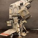
voozet Posted February 17 Author Share Posted February 17 I have a bit less time for modeling now, so progress is slow. But it's always a step forward. Implementing all of @Pete in Lincs suggestions initially seemed quite a challenge to me, but later I came to the conclusion that it was worth a try. A large collection of bits certainly makes it easier. Most of them are parts of 1:35 scale armored vehicles, so finding something suitable is quite easy 🙂 And here it is: the mecha-mega-vice. This time I'm definitely more pleased with the result. There is a worm drive, the whole thing is rotatable. I even managed to use what I had done before, although I modified it a lot. Thanks Pete! 🙂 As before - the beige elements are parts of a British tank. Probably suspension elements: springs or something similar. The spring was a bit too short, so on one side I added a piece of pipe that imitated a drive. I also had to cut off the fastening pins that I glued in random places as imitations of rivets/bolts/whatever. The rim of the wheel (grey), which is the mounting element here, fits perfectly with the forearm, thanks to this assembly of the whole thing does not require glue. This is convenient because it will make it easier to paint separately. My only doubt is whether the vice is not a bit too large compared to the hull. But I'm not going to do it again, so it doesn't really matter 😆 Now it's time for a second hand and a welding torch. I may add something else to it, to create a robotic multi-tool. We'll see. Edit: Here is a photo to illustrate the work so far. From time to time, I put together the already made elements to assess how they fit together. I see a few potential problems. The main one is the height of this model. The part of the hull containing the operator's cabin is so far from the ground that the tools may look bad. Especially the excavator. The reach of this excavator's arm doesn't seem to be enough to reach it Thanks for watching. Wiesiek. 12 Link to comment Share on other sites More sharing options...
Pete in Lincs Posted February 17 Share Posted February 17 You're very welcome my friend. That is exactly what I had in my mind. Well done. 👍 1 Link to comment Share on other sites More sharing options...
voozet Posted February 27 Author Share Posted February 27 I'm a bit stuck in the concept phase: I'm considering giving up on the excavator because it doesn't quite fit in size and, besides, I think it disturbs the model's proportions. I decided to finish the operator's cabin to do something else and after some time take a fresh look at the excavator. The operator module was already largely built, all that's left is to add some details. The green joysticks come from the Soviet BA armored car kit. The perforated copper sheet is the mudguard of a tank. I bought it as modeling scrap. These are foot supports. The control panel, made up of lots of little details whose origins I can't determine. I carved the operator's seat from 3mm styrene and mounted it on a frame made of thinner plastic. At the top there is a 1:35 fire extinguisher, I assume it is British. Safety first! As most of you probably know, adding details is a process that may never end. That's why I painted the cabin elements with a primer to stop the process of thinking about whether to glue something else to it. This is what it looks like without the top ring and seat. Thanks for looking! Wiesiek. 11 Link to comment Share on other sites More sharing options...
Uncle Monty Posted February 27 Share Posted February 27 Wow, lovely work on the cabin, very precise and clean. I hope you sort out your excavator issues soon 1 Link to comment Share on other sites More sharing options...
Hunter Rose Posted February 27 Share Posted February 27 Looks great! Lovely job carving that chair, it just looks like a spare you found! 1 Link to comment Share on other sites More sharing options...
voozet Posted March 2 Author Share Posted March 2 Thanks, gentlemen! The cab and operator's seat are painted. Thanks for watching. Wiesiek. 10 Link to comment Share on other sites More sharing options...

Recommended Posts
Create an account or sign in to comment
You need to be a member in order to leave a comment
Create an account
Sign up for a new account in our community. It's easy!
Register a new accountSign in
Already have an account? Sign in here.
Sign In Now