

Ex-FAAWAFU
-
Posts
8,366 -
Joined
-
Last visited
-
Days Won
49
Content Type
Events
Profiles
Forums
Media Demo
Everything posted by Ex-FAAWAFU
-
Totally agree about smaller punch & die. I use my RP P&D set all the time, & it’s great - but I’d snap your hand off if it went even smaller. P.S. Great to see this back, Rich
-
Harbour Air DHC-3T Vazar Otter (Single)
Ex-FAAWAFU replied to hendie's topic in Work in Progress - Aircraft
Bloomin’ gorgeous -
Close to finishing the life raft canisters…. & they’re a bit of a faff! Remove print supports; white primer (both sides, so 2 sessions); white topcoat (ditto); realise the underside, where the supports were attached, still needed some work with a file; white primer again on the filed section; white topcoat; finally thin (0.1mm) black pen for the rubber seal… But worth it, I think. The trouble with building a ship with over 500 ship’s company, designed to transport a complete tank batallion or a Royal Marine Commando… is that I need 70 of the blighters! More soon Crisp
- 214 replies
-
- 16
-

-

-
- 1/350
- Atlantic Models
- (and 1 more)
-
Westland Lynx SH-14D MLD - 1/32 Scale
Ex-FAAWAFU replied to Rob K.'s topic in Work in Progress - Aircraft
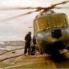
I am probably way, way too late to this particular party - and it’s a lovely build. It is true that the windscreen is not tinted on the Lynx, but it does have a heating element built into it, which from some angles can make it look very faintly gold. In this photo below (of “my” Lynx HAS3S, ZD260/346/BW of Broadsword Flight in 1990) you cannot really see the gold tint [it was *very* subtle], but you can see the white (actually silver in real life) edges of the heating elements. You can also see how dark the overhead panels often appear from outside. [I have a long-term idle dream of building this scene one day, but since it shows us doing a MRGB change alongside in Gibraltar, which necessitates removing both engines, you can probably imagine the amount of scratch building that would be needed! Probably never going to happen, though I will certainly build “Danny Boy” one day (the nickname one for you “Where Eagles Dare” fans…).] Anyway, as I said, superb build. Crisp -
Continuing with the LCVP davits, having got the brass davit support pillars nicely square I found that the torque bar wasn’t level (probs slightly off-centre drilling on my part): So a shim on the right (some spare brass from the PE runner) & some filing on the left, now improved: Finally time for glue! Here rather precariously balanced in situ on the superstructure: …and here with an LCVP test-fitted (nice & snug): More soon (though doubt there will be many photos, since it will essentially be the same repeated three more times!) Crisp
- 214 replies
-
- 17
-
-
- 1/350
- Atlantic Models
- (and 1 more)
-
Getting there; the hardest bit is replacing the white metal rod, and that’s done. More soon Crisp
- 214 replies
-
- 17
-
-
- 1/350
- Atlantic Models
- (and 1 more)
-
Terrible photo, & still some fettling required to square everything up, but you get the general gist. My policy of obsessively dry fitting everything has definitely paid off here; my drawings (side view, though not plan - & happily Peter has followed plan) have an error in them in showing the torque bar between the motors as running *outboard* of the assorted vents in this area, but as you can see from this, there’s no way that would work (one of 3 vent trunks dry fitted to check geometry): Confirmation from a photo of the real thing laid up in Fareham Creek awaiting disposal (& thus with no LCVPs): More soon Crisp
- 214 replies
-
- 18
-
-
- 1/350
- Atlantic Models
- (and 1 more)
-
Started to work on the 4 LCVP davits, which are a combo of PE & white metal (& a clever design). When the original kit was released, apparently the PE was too small to fit properly, but it’s a mark of the service you get from Peter that once he realised, he immediately re-designed it & sent upgraded PE out free & un-prompted. As with all white metal, it’s too soft to be convincing in the torque bar that sits between the two motors. Here you can see that I’ve replaced one with some 0.8mm brass rod, plus evidence for why that’s necessary! …and here three of the remaining motors after clean-up, & three still to do: This is what the component parts look like after folding the PE. The kit also provides the 70-odd liferafts that you need in white metal. They’re OK (though personally I think they’re not fat enough), but cleaning up 70 white metal canisters consistently would be really hard, & in any case the Swordfish Models printed versions are excellent. Here white metal to the left & a bunch of printed ones in primer: The real ones look like this, with the very prominent / visible black seal: An experiment with the thinnest black pen I could find suggests that the Swordfish ones will work nicely: Finally for now, I’ve started adding assorted vertical ladders, which will be the last detailing to be added before the bulkheads get primed. More soon Crisp
- 214 replies
-
- 18
-
-
- 1/350
- Atlantic Models
- (and 1 more)
-
The sea trays used to get pretty scuzzy, but the floor itself less so. Faded, sure, but not filthy; these cabs operated in a very salt-laden environment for their entire lives, so needed to be kept fairly clean
-
That’s not my workspace; it’s a storage area to the side of my workspace. You think I could do any kind of work with an 18” lump of resin sitting in the middle of my bench? Confucius says “If your storage areas are tidy, then you need to get out more…” P.S. this is the work bench:
- 214 replies
-
- 14
-

-
-
-
- 1/350
- Atlantic Models
- (and 1 more)
-
Operation Ghost Seam is complete; here after the Mr Surfacer had been sanded back: …and here after a fresh coat of the excellent MRP primer: I’ve also added a second coat of deck grey up for’d, after sanding away a few minor blemishes - but no photo cos it basically looks identical. While it cures fully (the only disadvantage of using the superb Colourcoats) I have been working on masks for the flight deck markings (top - which I am confident will work cos I did something very similar for Ark Royal 5), and the distinctive pattern of “elephants’ feet” [deck tie down attachment points] (bottom - which I am not aure will work but is worth a try): I’m away with work until Friday, but more soon Crisp
- 214 replies
-
- 15
-
-

-
- 1/350
- Atlantic Models
- (and 1 more)
-
Fairey Barracuda Mk II - Special Hobby 1/72
Ex-FAAWAFU replied to CedB's topic in Work in Progress - Aircraft
Bill is right! The ribs are inset into the belly of the mighty beast - the ribs that you are looking at are the underside of the Observer’s cockpit floor, onto which the torpedo & centreline bomb crutches were suspended for strength. Remember this was a dive bomber more than a torpedo bomber in active service, cos torpedo bombing had largely disappeared [indeed the very cab that you’re building made a right mess of Tirpitz by dive bombing her]. A fully-laden Barra weighed well over 6 tons, so was built like a brick outhouse to withstand the stresses of dive bombing (& my Uncle’s deck landings, obvs). I have a photo of a real Barra (courtesy of the magnificent DP872 restoration project at the FAA Museum [& if you don’t follow their weekly updates on yer Socials, you really should; they are endlessly fascinating!] that shows this clearly, but for some reason Flickr won’t play this afternoon. I suspect it’s a work filtering issue, so I will post it later. The ribs are not flush with the aircraft skin. Edit: here you are (yellow marks & “HERE” were to illustrate something from the restoration, so ignore); your oversized part (woof) is supposed to be the section on the right of the photo): -
Harbour Air DHC-3T Vazar Otter (Single)
Ex-FAAWAFU replied to hendie's topic in Work in Progress - Aircraft
Just caught up from the top. Blimmin’ lovely work, all of it - not that I was expecting anything else, obvs. -
Fairey Barracuda Mk II - Special Hobby 1/72
Ex-FAAWAFU replied to CedB's topic in Work in Progress - Aircraft
Got to love a Barra. You’re folding the wings, obviously? -
It included removal of *some* of the missiles; 1 remains on each launcher. Remember this build will depict her as she was sailing into Pompey in July 1982, so there was 1 drill missile (Oxford Blue) on each launcher. When it comes to doing my own version - as in San Carlos - all 4 missiles (white warshots) will remain on each launcher; there will then be a different problem to solve, since the prints are all with the launchers parked with missiles vertical, whereas in action they moved around.
- 214 replies
-
- 7
-
-

-
- 1/350
- Atlantic Models
- (and 1 more)
-
Preaching to the converted here, no doubt, but I continue to be astonished & enthused by the possibilities presented by 3D printing in our bonkers hobby. I have been cleaning up Swordfish Models Sea Cat launchers… …and Black Cat Models 40/60 Bofors Mk.7: 40/60 seen in situ (without barrel, obvs!): Also pleased with how the window masking on the quarterdeck crane cab has come out: Dry fitted on the (newly painted) port quarterdeck: You’ll also note that I have added a new layer of Mr Surfacer to the seam around flight deck / dock deckhead insert. It’s very thin so unsurprisingly has flexed a little since fitting, leading to ghost seams re-appearing. At least it happened *before* I painted it! more soon Crisp
- 214 replies
-
- 19
-
-
- 1/350
- Atlantic Models
- (and 1 more)
-
I have the Jamscrew Forth Bridge gear (the poles & clamps version of blade restraint) & it is highly recommended
- 304 replies
-
- 4
-
-
-
- 1/48 Sea Kings Wessex and Others
- Sea King Update
- (and 1 more)
-
Crane (& gantry) dry fitted to measure distances for the external wires: Plus the cab windows masked: More soon Crisp
- 214 replies
-
- 17
-
-
-
- 1/350
- Atlantic Models
- (and 1 more)
-
Attention turned back to the port quarterdeck crane over the weekend. This is essentially an exercise in logic, working out the right order to fold, prime fit internal parts, paint, etc. I had already primed the whole thing (inside & out) a couple of weeks ago, so the first job was to fit a couple of scratch-built wheels to the top section - Pete's PE has holes built into the bracket for these, so fitting them wasn't too bad once I had managed to get versions with roughly central holes for the brass rod shaft. Just a reminder of what the real thing looked like: I really wanted to get that effect of the wire running up the inside of the structure, which is where I really started to get into head-scratching decisions about the order to do things. Having come up with a plan, I first painted the whole thing inside (Colourcoats Light Weatherwork Grey BS381C-676) and, while waiting for that to dry, built a tiny single wheel to be fitted internally; you can see it just above the crane (which is upside down) in this picture: At this stage I still wasn't 100% sure I'd be able to pull this off - it's all bloody tiny! - but I thought it was worth a try. Time for another of those DSPIAE "don't-use-it-that-often-but-indispensible-when-I-do" tools, the "Precision Hand Stabiliser". I love this thing; with practice it is possible to keep your hand from shaking almost completely, which when you're working at this scale can be vital. Seen here on a test run: It worked! As you can see, I had pre-bent a length of 0.2mm copper rod to approximately the right angle, painted it black and glued it to the top of the wheel (we're still upside down here, it you are trying to get your bearings!). Here we are the right way up, with the internal wire visible - this was exactly the effect I was after, so I am really pleased. The next stage will be the external wires, which in theory ought to be easier - but to get the lengths & angles right I had to build the support gantry on which the crane jib rests when not in use; you can just about see it at the left of the real life photo above. Late last night I completed the brass bending, so the crane is now ready for the external wires; this is just a mock-up, obvs, with it dry-fitted to the cab. (Black paint is ready for masking to make the cab windows). Might not look like much, but that's a full day's modelling! More soon Crisp
- 214 replies
-
- 22
-
-
-
- 1/350
- Atlantic Models
- (and 1 more)
-
Been working on the characteristic white HF pole aerial seen at the masthead of most RN warships of this period (seen here on FS in San Carlos Water): The kit provides a white metal job, but I know from previous builds that it is very hard to get it really cleaned up so the edges are crisp. So I’ve spent the afternoon with some 0.8 mm brass rod & a pack of Albion Alloys’ superb “slide fit” brass tube (1.1 mm, 1.3 mm, 1.5 mm & 1.7 mm in this case), a clean scalpel blade & a fair amount of swearing… to build this: All 4 sizes of slide fit tube are used, though the 1.3 mm is invisible inside the two sections of 1.5 mm. In due course to be painted white and installed here: Also prepared a lot of small resin pieces for primer - probably tomorrow rather than today. More soon Crisp
- 214 replies
-
- 19
-
-
- 1/350
- Atlantic Models
- (and 1 more)
-
Further be-greeblement, this time the waveguides leading from the SATCOM shack in front of the mainmast up to the SCOT aerials. This is probably the clearest 1982 photo of what I am talking about: …and here my attempt at something like it, using styrene strip & nickel silver tube: And finally with added sirens - adapted from the Airfix Illustrious kit, trimmed down for size & drilled to give a semi-hollow ‘horn’ section: More soon Crisp
- 214 replies
-
- 14
-
-
- 1/350
- Atlantic Models
- (and 1 more)
-
The final few bits of detailing on the sides of the superstructure before we get to primer. First the pre-wet pipes (to wash away nuclear fallout) [nickel silver] & bridge wing drainage [styrene] on the starboard side: Ditto port: Here port again, also showing a further drainage pipe abaft the funnel, plus the fact that I have also masked the small deckhouses midships: Finally for now, started working on the mainmast; this is the forward face, which will be very hard to access once it’s glued in position: More soon Crisp
- 214 replies
-
- 22
-
-
- 1/350
- Atlantic Models
- (and 1 more)
-
The first actual paint - specifically, Colourcoats NARN54 RN Dark Deck Grey - on the fo’c’s’le. As ever, it sprays beautifully: I also started on the decks of the superstructure, but a bottle of MicroSol fell off a shelf over my bench & hit the starboard bridge wing, cracking the resin - you can see the crack here: That was the bad news, but it was readily fixable so no huge problem…. but should explain why starboard forward part of the superstructure remains primer only! At least one more coat will follow. But it’s a good start! I am away with work for a few days, so this will be it for a while. Crisp
- 214 replies
-
- 24
-
-
- 1/350
- Atlantic Models
- (and 1 more)