Search the Community
Showing results for tags 'Miniart'.
-
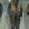
Dear Fellow Modellers After many many months I finished the Miniart Stug III G March 1943 production with winterketten. Completing these kits leave you with mixed emotions. Relief at finishing the project and a sudden desire to build something incredibly simple, as well as admiration for what Miniart has achieved and how much you now have a feel for the original designers and the crew members. To complement the winter markings I added the Miniart winter figures. There are many great modellers out there who's work almost make them artists. So at first I felt a bit daunted doing a winter scheme as these are often used to showcase modellers finishing and painting skills. But it turns out it couldn't be simpler! Just mist on white over the undercoat of dark yellow from the bottom upwards. Then finish with Mig oilbrushers and pin wash and you're done. And earlier days in the build One of my inspirations was the Australian 'Workshop Wednesday' where experts at their armour museum painstakingly repair a wrecked Stug III and film it on Youtube. The degree of engineering refinement of the Stug III (and therefore its parent Pz.kpfw. III) is astonishing and completely at odds with the need to mass produce a tool that was sufficiently good enough. As if German Industrialists secretly sabotaged Hitler's war of world domination by producing vehicles that were insanely complex and difficult to mass produce. Completely different from the T-34 and Sherman of other nations. Hope you like it Andrew
-
 MiniArt is to release 1/48th Republic P-47D/M Thunderbolt kits. Source: https://miniart-models.com/wp-content/catalogue/2022/index.html - ref. 48001 - Republic P-47D-25RE Thunderbolt - advanced kit - released - https://miniart-models.com/product/48001-p-47d-25re-thunderbolt-advanced-kit/ - ref. 48003 - Republic P-47D-26RA Thunderbolt - advanced kit - released- https://miniart-models.com/product/48003-p-47d-26ra-thunderbolt-advanced-kit/ - ref. 48009 - Republic P-47D-25RE Thunderbolt - basic kit - released - https://miniart-models.com/product/48009-p-47d-25re-thunderbolt-basic-kit/ - ref. 48012 Republic Thunderbolt Mk.II. - Royal Air Force - advanced kit - released - https://miniart-models.com/product/48012-thunderbolt-mk-ii-royal-air-force-advanced-kit/ - ref. 48015 - Republic P-47D-28RE Thunderbolt - basic kit - released - https://miniart-models.com/product/48015-p-47d-28re-thunderbolt-free-french-air-force/ - ref. 48018 - Republic P-47D Thunderbolt with base and accessories - Big set - released - https://miniart-models.com/product/48018-thunderbolt-p-47d-bubbletop-with-base-accessories-big-set/ - ref. 48022 - Republic P-47D-28RA Thunderbolt - Pacific theater of operation - basic kit - released: https://miniart-models.com/product/48022-p-47d-28ra-thunderbolt-pacific-theater-of-operations-basic-kit/ - ref. 48023 - Republic P-47D-30RE Thunderbolt - basic kit - released - https://miniart-models.com/product/48023-p-47d-30re-thunderbolt-basic-kit/ - ref. 48029 - Republic P-47D-30RA Thunderbolt - advanced kit - released https://miniart-models.com/product/48029-p-47d-30ra-thunderbolt/ - ref. 48034 - Republic P-47D-11RE Thunderbolt - Zemke's Wolfpack - advanced kit - release in 2025 https://miniart-models.com/product/48034-p-47d-11re-thunderbolt-zemkes-wolfpack-advanced-kit/ - ref. 48037 - Republic P-47D-11RE Thunderbolt - basic kit - release in July 2025 - https://miniart-models.com/product/48037-p-47d-11re-thunderbolt-basic-kit/ Have a look at the kits reference numbers, there's room enough for Mustang, Spitfire, Bf.109, Fw.190, Zero, Hurricane etc. 😜 V.P.
- 343 replies
-
- 8
-

-
- P-47
- Thunderbolt
- (and 1 more)
-
For my first ever GB I went big, Aussie M3 Lee with full interior. Last time I've attempted to do full interior kit was 20+ years ago with Tiger I from Academy, sadly got distracted and the only thing I was able to finish was the turret. This time I plan to go all the way. I don't have any connections with lands down under except having a couple of good mates from my bmx years, both Kiwi born and bread, one near Wanaka and one in Wellington. Anyway, I digress. The part count is bigger than I expected and it looks like there will be quite a lot of work involved. Sprues look really good with quite sharp details and a few PE parts. My plan is to have all doors open, so that it will show as much interior as possible.
- 55 replies
-
- 18
-
-
Hello. Another birthday present build. I'd had my eye on a Tamiya T62. I built one years ago and brush painted it in a Afghanistan green and yellow camoflage pattern but then saw this T54 with a two tone camo pattern and thought why not? This is going to be a strictly OOTB build. That lasted the lenght of time it took to get the kit home! The kit is a simple low parts offering from Miniart. Just a few sprues. So the deviation from OOTB is a set of decals from STAR Decals. What caught my eye was this scheme from Angola. The only issue that I can see is that the hull in the illustration is a late version? If any one can help with identifying this I'd appreciate the advice. Are these features typical of late hulls and are they the only difference? I've noticed that the Miniart Tiran 4 kit has these features. If a change of plan and paint scheme is necessary, so be it. Anyway on with the build. Boy there are a lot of pieces. All of the openings for the swing arm attachement points needed attention to prevent the lower hull from curling up. The holes for the torsion bars all needed drilling out with a 1.2mm bit to fit. They also went together by feeding them in the opposite direction to the instructions I found. I followed the instructions diligently because of the parts count until it came to assembling the hull. Squaring it up with lots of easily damageable parts attached seemed crazy. The fit is OK but I found the fire wall pinched the top plate so it needed prizing apart. After assembling the engine deck louvres I found they wouldn't sit right due to a tiny handle(partR41), which was removed to solve the problem. There is some nice detail here and it's a shame it will all be hidden by photo etch. Once the hull was set the detail has started to be added. I'm really impressed with the level of detail that comes with this kit but consequently there are some seriously tiny parts. Thanks for looking
-
Sd.Kfz.234/2 with ‘Luchs’ Turret (35416) 1:35 MiniArt via Creative Models Ltd Armoured cars and their derivatives were a dominant part of German military thinking after WWI, as they were prevented from having tanks or other types of heavy weaponry by the Versailles Treaty, at least until they unilaterally set its terms aside once Mr Hitler was firmly ensconced as the country’s mad dictator. Although it closely resembles the earlier Sd.Kfz.231, the 234 was based upon a more modern ARK chassis, while the 231 was built on the GS chassis. The 232 Schwerer Panzerspähwagen was available in 6- or 8-wheeled formats, with the number of wheels appended to the designation, and it was the 8-Rad that the basis for the 234, following on later in 1940 and learning from issues encountered with earlier designs. The new turret was designed by Daimler Benz, while the engine was a Tatra air-cooled diesel unit, powering all eight wheels that were also all steerable. To add to the ease with which the vehicle could be driven, there was an additional driver’s station at the rear of the crew cab, complete with a steering wheel that gave it the capability of reversing out of trouble with similar sped and dexterity as driving forward – a facility that came in very useful in the event of an ambush or stumbling into an enemy position. The 234/2 was the initial variant and the most prevalent, as well as being the best known, probably because of the (comparatively) large 50mm gun in the turret. Oddly, it was replaced less than a year later with an open-turreted /1 variant that mounted a smaller 20mm cannon, and concurrently another variant with a short-barrelled 75mm K51 gun under the /3 designation. This variant was also short-lived, increasing the fire-power substantially with an installation of the powerful Pak 40, although the extra weight caused extreme stress to the 234’s chassis and running gear. All the variants after the /2 were open-topped, leaving the crew exposed to the elements, incoming plunging fire and explosive charges or grenades lobbed in by the enemy. To keep the enemy out of range however, a single MG42 was coaxially mounted with the main gun - a very capable machine gun against troops and lightly armoured targets. The armour built into the vehicle could deflect light-arms and smaller cannon rounds, with 30mm of sloped armour on the turret, and up to 100mm thickness on the mantlet, but at the rear the protection was only 10mm, as was the roof of the /2. Over 100 /2 vehicles were made before it was superseded, and despite being the most well-known, there were around 200 of the later /1 produced, with roughly 90 of each of the other two made before the war ended. The Kit This is a new boxing of a very recent tooling from MiniArt, a new Interior Kit boxing that represents the variant of the 234 that utilised the lower-profile turret from the earlier Panzer II Luchs, which the original larger turret was intended to replace on the new VK16.02 Leopard platform that was cancelled before it reached prototype. We’ve had other kits of the type in this scale previously, but not for some considerable time, and it’s fair to say that armour modellers with an interest in this genre are very pleased. The kit arrives in a standard-sized top-opening box with a painting of a Luchs-turreted 234/2 travelling across a smoky battlefield with other German armour in the background. Inside the box are twenty-three sprues of various sizes in grey styrene, a clear sprue, a fret of Photo-Etch (PE) brass, decal sheet, and the instruction booklet that is printed in colour on the outer pages on glossy paper, with profiles of the decal options on the rear cover. The detail is excellent, extending to the full interior for this boxing, following on from the initial exterior-only version we reviewed recently. The full gamut of hatches can be posed open or closed to expose the details, PE parts, and the surface is fully realised with weld seams and exterior structure well defined. Construction begins with the lower hull, starting with the narrow bottom section where the drive-shafts and suspensions are located, which is made from three faces, two internal bulkheads, and two steering actuators, one at each end. The hull floor has tread-plate moulded-in and a cut-out ready for the interior, sandwiching it between the two outward sloping sides, drilling out holes in the parts before assembling them, adding a rear bulkhead behind the engine compartment. The two assemblies are mated, fitting the first parts for the suspension to the sides, and a U-shaped stiffener in the centre of the lower portion. The interior starts with the two drivers’ positions, fitting the floor section after drilling out holes for the pedals, three for the rear driver and four for the main driver at the front, adding linkages down both sides of the engine compartment, and fairings on the left side of the hull, plus a battery compartment and fairing on the right that is built from five parts, fitting a shallow frame in front. The drivers have their steering columns and wheels attached in recesses, the main driver’s being a more comprehensive installation. A two-part seat is fixed to the rails moulded into the floor, with a linkage and gas mask canister to his left, and a five-part shell stowage box fitted to the wall behind his left shoulder. The battery rack is wired into a distribution box on the right wall, using wire from your own stock, then inserting the two levers to the driver’s right, noting that the scrap diagram shows that the wires to the battery are braided and thick to cope with the level of current. The rear driver’s station has the same pair of levers fitted, mounting a seven-part two-box radio rack, another small equipment box to his right, and an ammo stowage box behind the front driver’s right shoulder. The rear driver also gets a two-part seat, and an additional lever that’s probably related to taking control from the main driver. A skeletal bulkhead is inserted into a groove on the inside of the hull, fixing a seven-part bulkhead for the engine compartment behind it, which has a circular seat projecting out into the fighting compartment under the turret ring. A folded MP40 on a bracket is fitted above the right-hand side door within easy reach of the rear driver. The engine is a substantial block, weighing in at 14,825cc, and is a V12 diesel manufactured by Czech manufacturer Tatra, and it is supplied in its entirety in this boxing. The piston banks are each made from four parts, held together by the end-caps, adding extra parts around the underside, and at both ends, utilising a lot of parts that includes the ancillaries, twin cooling fans, fan belt, dynamo, and if you feel brave enough, you can wire up the engine using the extra steps that are labelled for “advanced modellers” that run side-by-side with the main steps. The completed engine is an impressive size, and covered with detail, especially if you continue with the wiring that helps to integrate it with the chassis. A pair of four-part tanks are inserted to the sides of the engine, with two extra parts for the doors either in the open or closed position, as you see fit. The upper hull interior has several appliqué panels, gas mask canister, the driver’s instrument panel, another radio box and other inner structural parts, plus the vision ports applied, adding hinge-points for the driver’s hatch and building three vision ports for later installation, and a stowage box. The upper hull has the engine deck filled with cooling vents that can be posed open or closed by using different parts, with two solid doors at the sides that can also be posed open, locating it in the cut-out in the back of the deck, then adding the rear bulkhead with hatch that has four “milk bottles” on the inner face if posing it open, mating the upper and lower hull assemblies, fitting the vision ports and a hatch with separate hinges and handles in the square cut-out in the glacis plate, again in either open or closed position, as you might have guessed. Suspension and steering parts are assembled on the underside of the hull, making up four axles and leaf-springs on each side, replacing left with right-handed hubs on the relevant side. Six triple-handled Jerry cans with PE central weld-flares and filler cap are made and wrapped in PE straps that secure them to the vehicle later, making up both sides of the sponsons and installing the rear carcasses of the flush stowage boxes, adding the external parts such as the jack, two mufflers and another stowage box, finishing the sponsons and their ends with additional parts. The doors can be fitted open or closed by using different parts, with a selection of stowage boxes made up and used. The spare wheel is the first to be made, making it from either three tread laminations and two exterior faces to create a detailed tread pattern, or using a simpler two-part wheel structure if you prefer, fitting it to the bracket on the rear of the vehicle, in between the mufflers on either side of the sloped rear of the sponsons. More stowage boxes and Jerry cans are mounted on the engine deck and front fenders, plus pioneer tools and a fire extinguisher on the left sponson. More detail parts are dotted around the hull, including width-marker lollipops, headlight, an antenna with PE star-shaped tip, then crushing it all while you fit the tyres (I hope I’m joking here), which are made from two halves and a tapering hub that will be seen once the wheels are installed on the four axles. The turret floor, such as it is, is first to be detailed, adding a radio installation with twin seats to the sides, plus an L-shaped assembly with adjustment gear, fitted in the rear and front of the ring respectively, and joined to the rear with a set of headphones with a PE band joining the “cans” together. Adding some fine wire to link the phones to the radio will add a little extra realism here too. The 20mm recuperator is fixed on a support under the breech, which has a magazine slotted into the left side, sliding the assembly into the narrow mantlet, adding end caps and sighting gear, plus a coaxial machine gun, before mounting it in a frame, which allows the outer mantlet to be fixed to the exterior on a pair of conical supports at the ends. The rear of the turret has a large hatch in the centre, and is detailed inside along with the triangular sides, one of which has a viewport that can be built in the open or closed position by using alternate parts, putting the mantlet, sides and rear together on the turret base that allows the roof to be installed after some detail parts are added inside. The rear hatch can be posed open or closed, adding a handle and PE for both choices, with a handle above the hatch, a cover over the vision port, and a rotating periscope on the roof. The top hatch also has a rotating insert with periscope in the centre, which fits inside the outer rim with hinges added at the rear. Unsurprisingly, this too can be posed open or closed, fixing it open with a short stay next to the hinges. You have a choice of making the gun barrel from a single part, or by cutting off the conical flash hider and rolling the PE replacement to shape, you can have an in-scale tip for extra realism. The coax MG34 muzzle is fitted into a hole to the left of the main gun, adding an aerial to the back of the roof to finish it off. To finish the build, the turret is dropped into the ring, which doesn’t have a bayonet lock, so you’ll need to be careful when inverting the model in the future. Markings There are two decal options in this boxing, both with a base-coat of dark yellow, one with a hypothetical winter distemper camouflage. From the box you can build one of the following: Presumably Panzer-Aufklärungs-Abteilung 17, 17. Panzer-Division, Czechoslovakia, Spring 1945 Hypothetical winter Camouflage Panzer-Aufklärungs-Abteilung 17, 17. Panzer-Division Decals are by Cartograf, which is a guarantee of good registration, sharpness and colour density, with a thin matt carrier film cut close to the printed areas. Conclusion The Luchs turret adds a little rarity value to the /2, and while it doesn’t have the 50mm barrel of the standard variant, the lower profile gives it a sleeker look, if that’s at all possible. Detail is excellent, and this interior kit will keep you at your workbench for many a happy hour. Highly recommended. At time of writing, this kit is on a substantial discount with Creative Review sample courtesy of
-
M3 Stuart Early Prod (35412) 1:35 MiniArt via Creative Models Ltd The M3 Stuart was designed before the US went to war, based upon the experiences of the British, which led to the US top brass deciding that their M2 light tank was obsolete. While the radial engined M3 was an improvement over the M2, it suffered from an underpowered M6 main gun at only 37mm, which although it was improved later in the war, the crews had to suffer with it for some considerable time. The British troops in Africa used it first against the superior tanks of the Afrika Korps, but they fared badly in combat, suffering from the lack of range of the Stuart in the wide-open spaces of the African desert. It was fast and manoeuvrable however, and a British driver’s comment that she was a "honey" to drive led to one of its nicknames during the war. The M3A1 was an improved version that deleted the heavy sponson mounted machine guns of the initial production, and some of these used more conventional diesel engines instead of the bulky radials, which gave the crew more room for other equipment. It also had a new turret with a basket for the turret crew to stand in, and no cupola for the commander that gave the tank a lower profile, and added a gun stabilisation system that helped with vertical alignment of targets while the tank was on the move, ironing out the bumps for the gunners. In British service it was known as the Stuart III and with the diesel engine version was designated the IV. It was hopelessly outclassed by Axis armour in Europe for tank-on-tank engagements however, and was soon relegated to infantry support and recce roles, where it performed well. It was more successful in the Pacific theatre against the lightly armoured Japanese tanks in the jungle, where medium and heavy tanks could soon flounder in the mud and heavy foliage in jungle conditions. It continued to be used to the end of the war by the Allies in the Pacific area, although Russia, another user of the Stuart, disliked it intensely and refused to take the upgraded M5 design that followed the M3A3. Variants were used well into the 60s, and Brazil even built their own version with redesigned upper hull that carried a 90mm gun. Paraguay still had a few of its ancient original stock of 12 beyond the turn of the millennium, which is astonishing, considering the age of the design. The Kit This is a new boxing of a very recent tooling from our friends at MiniArt, who are producing an amazing output of new kits and partial re-tools in recent years, which is doubly-impressive given the abominable situation in Ukraine over the last few years. This kit arrives in a top-opening box with a painting of an early production Stuart on the front, surrounded by a herd of zebras, which gives its location as Africa, unless it was plundering through a zoo. Inside the box are twelve sprues of various sizes in grey styrene, a clear sprue, a fret of Photo-Etch (PE) brass in a card envelope, a decal sheet, and the instruction booklet, which is printed in colour on glossy paper, with profiles of the decal options on the rearmost pages. Detail is excellent as we’ve come to expect from MiniArt, and as this is an exterior kit, the interior isn’t provided, but the exterior and running gear are well-defined, and the tracks are supplied as link-and-length, taking the benefits of individual links and making the job a lot less labour intensive without much loss of detail. Construction begins with the vehicle’s floor with a choice of two styles of floor hatch, then making curved transmission armour at the front of the tank, which is detailed with various towing eyes, additional bolt heads that are cut from the sprue runner, and a central frame that can be folded from PE or replaced by a single styrene part. Now the hull sides can be fitted, but not before they are detailed with various external parts, adding final drive housings to the front ends, using the bogie axle ends to locate the parts on the sides of the floor. The rear bulkhead is built with a hatch space in the upper half, gluing it to the rear of the vehicle. The rear hatch is in two sections, one of which has a PE clapping plate, both having handles, posing them closed to hide the lack of engine. Above the hatch is an overhang with a PE mesh horizontal insert and styrene rear, with a couple of towing eyes mounted on the lower edge of the bulkhead. The next assembly is a thirty-cal bow machine gun, which has a vertical magazine moulded into the underside of the breech, finished with a circular mount that is slotted through the glacis plate from the inside, plus a strengthening strap under the driver’s hatch. It is glued into position on the front of the tank, fitting the transmission inspection hatch with handle in the centre, and adding a pair of towing shackles to the front. The driver’s hatch is in two parts, and can be posed closed for battle, or with both parts folded open to allow the driver to see the full vista, which would of course expose the lack of interior. A two-layer T-shaped cross-member is located over the upper glacis, adding a bracket that supports the headlamp, and a pair of bearing spacers to the final drive housings. As already mentioned, the earliest Stuarts had sponson-mounted machine guns, which extend from the main hull out over the tracks, roughly along the middle third of the vehicle’s length. The two sponson floors are glued into position, and two .30cal machine guns are trapped between two-part mounts, one fitted to each sponson, sliding through the front armour. The sides of the sponsons can then be built around the guns, with a short wall to the rear, and a long panel along the side. Two hatches are fixed to the front of the upper hull after adding an extra layer behind, a clear vision port, and openers to the sides. If you intend to pose the hatches up, you have the option of leaving the inclement weather inner hatches in position, which have large panes of glass and windscreen wipers to save filling the tank with precipitation. The open outer hatches are propped up with a pair of short stays from their top hinges, but the usual caveat about the interior still applies. The hull roof is next, starting with the panel that has the turret ring moulded-in, adding additional nuts on the top ring from the sprue runners, and a pair of filler caps on the deck behind it, shaving away clasp details around them. The completed part is lowered into place on the hull, turning to the engine deck next, placing the panel after fitting handles, gluing it in position and fitting a pair of rear lights on brackets to the sides, adding a little connecting wire if you wish. The main deck panel has a PE shroud to the forward edge to deflect incoming rounds or debris, plus another PE bracket for one of the aerials is attached to the right, with another shelf-bracket mounted on the side wall slightly lower and further to the side than the other. The aerial bases are each made from two parts, adding 73mm of stretched sprue, wire, or carbon fibre rod to represent the aerials themselves. A pair of dome-topped cylindrical air-boxes are built from four parts each and are attached to the rear of the sponson on brackets on both sides. We finally get some wheels for the tank, starting with the two-part drive sprockets and a pair of over-size idler wheels, which are trapped between two halves of the swing-arm, adding a PE rim to both sides. The road wheels are mounted in two-wheel bogies, each one made from ten parts, building four in total, handed for each side. The road wheels flex-fit into position between the arms of the bogies, so that they can be mounted on the sides of the vehicle in shallow recesses along with the idlers and drive sprockets, with three return rollers on short axles above the main run. As discussed earlier, the tracks are link-and-length, using long single-part lengths under the wheels, individual links around sharp curves, and shorter lengths where the tracks are relatively straight. The various sections are attached to the sprues at the edges, and each short portion has a unique tab and slot format to ensure that parts can only be put together in the correct manner. There are a few ejector-pin marks on the inside of the longer track link sections, but these are raised and on flat surfaces, so shouldn’t be difficult to remove with a sanding stick or sharp blade, and won’t slow you don’t too much. When the track runs are suitably cured, fenders are added over the open areas, the rear straight sections fitted with a curved end to reduce kicked up mud, while the front section have inner side skirts to prevent mud ingress, which is improved further by gluing a PE web between it and the leading edge of the glacis plate, along with a PE stiffening strap further back. Before we start festooning the vehicle with pioneer tools, a pair of headlamps with clear lenses are placed, one on each fender protected by a PE cage, and both with a short length of wire leading back to hole in the glacis plate. The pioneer tools are fully styrene tools that have their clasps moulded-in, and are dotted all over the horizontal surfaces of the vehicle, including an axe, pickaxe shaft and head, and a shovel. More tools are located on the forward sponsons, adding PE tie-downs around the deck for securing stowage or camouflage. The twin towing rope requires the modeller to provide either a 157mm length of braided wire or thread, fitting a pair of styrene eyes to the ends, and clamping it in place with PE brackets along the left sponson and fender. Now for the turret, starting with the main 37 mm M6 gun, the gun tube formed by a single part with hollow muzzle that is surrounded by a two-part frame, and has the halves of the breech closed around the rear, adding extra detail on the right, and a breech protector to the left side, followed by a four-part pivot that are fixed around the gun without glue, then the coaxial machine gun is attached to the right side of the breech, and its ammo box is located on the left side, fed by a ‘bridge’ of link over the main gun in a guide to the breech of the smaller gun, dumping spent rounds in a box-like bag underneath. The barrel is pushed through the mantlet and inserted into the front of the turret, which has been made from a well-detailed ring, with the faceted turret sides arranged around it after being detailed with vision blocks themselves. The roof has a yoke inserted on its underside in stowed or combat positions, and is glued in place, sliding the mantlet armour over the main and coax guns from in front. The commander’s cupola is similarly faceted, and each side is prepared by fitting a vision block in the slot, creating an asymmetrical hexagonal shape, and deciding whether to pose the turret crew’s vision ports open or closed. The commander's hatch is a flat panel with a lock on the upper edge, and hinges on the lower, which can be fitted open or closed, with more vision ports on the turret sides posed open or closed around the rest of the perimeter. Another .30cal machine gun is trapped between a two-part mount with adjuster handle, and fixed to a short column that is secured to the rear left side of the turret on curved brackets moulded into the surface. An optional two-part ammo box with a length of link can be fixed to the side of the gun, or if you wish to leave it off, an alternative stub part is supplied in its place. With that, the turret can be dropped into position to complete the model. Markings There are six varied decal options included on the small sheet, and you’d still be almost correct if you guessed that they are all in some variation of WWII Allied green, with only their individual markings to tell them apart. The exception is the specially painted 1,000th tank produced, which was painted white to stand out for the ceremony. From the box you can build one of the following: 192nd Tank Battalion, Luzon, Philippines, December 1941 2nd Independent Tank Company, Free French Forces, Kano, Nigeria, 1942 American Car & Foundry Plant, 1,000th Tank 192nd Tank Brigade, Red Army, Volkhov Offensive, Oryol Region, Summer, 1942 US Marine Corps., Australia, Spring, 1943 Brazilian Army, 1944 Decals are by Cartograf, which is a guarantee of good registration, sharpness and colour density, with a thin matt carrier film cut close to the printed areas. Conclusion It’s great to have this much detail present in a newly tooled kit of the diminutive Stuart, or Honey as the Brits called it, and it deserves to become the de facto standard for the scale. If you don’t want to pick up the original Interior kits because they contain too many parts or will keep you occupied to long, then this one should fill the gap perfectly. Very highly recommended. At time of writing, this kit is on heavy discount from our friends at Creative Models Ltd. Review sample courtesy of
-
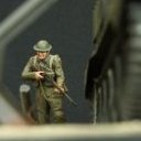
This is the reasonably new Miniart kit with crew figures in 1/35. If it's detail and parts you want, this is the kit for you. There's multiple decal options which require many different parts for different configurations of tank. There is also an extensive photo etch fret. I have deviated a little from the instructions; I changed the road wheels to the open kind and included the heavy machine gun on the cupola for this version as I liked the look. I also played around with the tools and stores on the tank. The kit includes 4 figures. I didn't use the bloke squatting down as I thought it looked like he was taking a dump. I did however cut off his hands and put them on the figure sitting in the turret as I liked them better than the closed fisted hands supplied. AK-47s come from the spares box. I decided to use a brush for this model as I figure it probably wasn't all nicely spray painted with and air gun, more likely being painted with a brush, or mop. I like the hard edge to the camo pattern this gives. Weathering was done with various washes and sandy pigments worked into the surface. These Miniart armour kits are very nice, but require a lot of work due to the high parts count and complexity of the build. I also found the plastic very soft and broke several smaller pieces trying to get them off the sprue. It's also worth noting these don't have anything like the Dragon Magic tracks, so every track link has 4 sprue attachment points to cut and clean, times by about 150 links. That said, patience will result in a nice looking model. I do have their T-55 and Panzer IV in the stash to build as well.
-
Spherical Fighting Vehicle TsAMO Project Interior Kit (40003) 1:35 MiniArt via Creative Models Ltd This is a hypothetical design from an alternative reality where ball-tanks were practical, and although there are some quite realistic looking pictures out there on the web, this is a decidedly fictional or "what-if" design for a small infantry tank that might have been quite handy for approaching bunkers or installations with significant light weapons presence. It does appear to have some critical weaknesses though, such as the little outrigger wheels that if shot out, would result in a seriously dizzy crew at best, so it's probably for the best that it remains in the realms of the fantastic. The ball hull is static, with a wide track running around the circumference, propelled by the motor inside. There would be some serious torque transfer to the hull on acceleration or deceleration, but as this doesn't seem to adversely affect those big-wheel motorcycles, it wouldn't be a huge impediment, especially as the major part of the hull won't be moving. There is a crew of five, with the top-most crew member in each side operating the weapons stations, and the front-facing crew driving and crewing the forward machine gun. The final crewman operates another machine-gun that faces to the rear. Oddly, the main guns face sideways in ball-mounts, which would make shooting straight ahead difficult without cooperation from the driver, which could be tricky in such a confined, noisy environment. In reality, it would probably have been an abject failure, but it's an interesting concept nonetheless. The Kit The first boxing of this kit was MiniArt’s initial foray into What-if or ‘alternate timeline’ subject-matter, arriving on the shelves in 2018. A lot of effort had been put into making it appear believable however, including a complete interior, which gives the model more gravitas and believability than an empty hull otherwise would, and opens up the possibility for dioramas or vignettes. The kit arrives in standard sized MiniArt top-opening box, with a painting of a pair of ball-tanks passing a knocked-out German Panzer, and inside are 23 sprues in mid grey styrene of various sizes, a single sprue of clear parts, and a decal sheet. The instruction booklet is bound in a glossy colour cover, with greyscale drawings inside, and the decal options printed on the inside covers front and back. Detail is good for a relatively small kit, and I have to say that this is just the kind of silliness that appeals to me, as it is at least semi-believable, whilst coming firmly from the left-field. Construction begins with the engine, which is quite a complex assembly, and has a large friction roller at the rear to apply power to the track. The crew seats are built up next with foot steps to keep their feet out of the way where appropriate, and then they are attached to the main frame, which consists of two large hoops with cross-members to hold them apart, and retain its shape. Track rollers are fitted to the inside of the frames, with the engine, seats, a fuel tank on a support rack, and ancillary equipment all suspended from this. Ammo racks for the main guns are built up at the same time as the gun breeches and the machine guns, which also have spare ammo cans made up, and all these sub-assemblies are installed into the hull halves, which have cut-outs for the ball-mounts, a radiator grille (backed with a standard-looking radiator), and conformal tank that could contain fuel or ballast. In the centre of each side is a large crew hatch that is operated by a wheel, with curved hinges and interlock mechanism included. With the breeches and machine guns fitted from the inside, and the hatches put in their required positions, the halves are glued to the frames, and the hollow tipped gun barrels are added, plus a headlight with clear lens for night operations (ha!). The track is supplied in four parts with a smooth tread and perpendicular joins to simplify clean-up. The four parts glue around the open section of the hull, and of course the two "trainer-wheels" that stop it from tipping over. The last diagram shows the option of leaving one or both hatches open to expose the interior. Markings As it's all fiction, it's probably more a case of choosing one of the six schemes that appeals to you, and it should be pretty easy to find one you like. You can of course mix and match decals and schemes, as no-one (sane) is going to be complaining that it isn't accurate. From the box you can build one of the following: Unidentified Unit Red Army, Spring 1942 13th Motorcycle Regiment, Red Army, Summer 1942 29th Guards Tank Corps, Red Army, Summer 1943 Unidentified Unit, Red Army, Summer 1944 Captured 5. Panzer-Division, Wehrmacht, Kursk, Summer 1943 Captured unidentified Unit, Italy, 1945 Decals are by Cartograf, which is a guarantee of good registration, sharpness and colour density, with a thin matt carrier film cut close to the printed areas. Conclusion An awesome trip into alternative history that's got a certain hokey appeal, partly because it looks like it could possibly have worked, although it only takes a moment to identify its critical weaknesses. The internal structure has been well thought-out, and the variation in decal options makes for a fun project that shouldn't take too long to complete. Very highly recommended. Review sample courtesy of
-
I completed my tandem SdKfz 235/3 Stummel builds. The Miniart and Dragon kits are both excellent and were a lot of fun to build. The Miniart kit: The Dragon kit:
- 11 replies
-
- 29
-
-

-

-
I’m not much of a figure painter but I do like to do a tank crew for most of my vehicles. I finished a British armoured bulldozer most recently and to go with the base I have painted one of miniarts royal engineers. These are relatively nice figures although the faces could use an uplift and details a little soft in places. I haven’t seen this set released with the resin heads yet like they do with a lot of their figure sets. Built out of the box other than the addition of the rifle sling. Few gaps that needed filling but went together well other than that. Close up photos highlight the roughness of my paint work but I think he looks decent from a normal viewing distance! Feedback welcome.
-

MiniArt Construction Workers (38097) 1:36
Mike posted a topic in Diorama, Accessories & Themed Figures
Construction Workers (38097) 1:35 MiniArt via Creative Models Ltd This new figure set from MiniArt Models depicts a pair of construction workers, or builders, hard at work laying bricks on a site, accompanied by their work-a-day equipment. It arrives in an end-opening figure-sized box with a painting of the contents on the front, and the same artwork split and covered with blue-boxed numbers for painting, and black alpha-numeric codes to match the sprue and part numbers, plus brief instructions to the side that detail creation of the multi-part accessories, and a paint chart that gives codes for Vallejo, Mr Color, AK RealColor, Mission Models, AMMO, Tamiya, plus colour swatches and generic names for completeness. Inside the box are five sprues of grey styrene of various shapes and sizes, two containing the figures, the rest their accessories. The parts for each figure are found in separate sprue for ease of identification, and parts breakdown is sensibly placed along clothing seams or natural breaks to minimise clean-up of the figures once they are built up. The sculpting is typically excellent, as we’ve come to expect from MiniArt’s artists and tool-makers, with natural poses, drape of clothing and textures appropriate to the parts of the model. The two figures are dressed in un-tucked shirts and trousers, with a beret or cap on their heads, one of them laying bricks with a large mortar trowel and an apron keeping mortar splashes off his clothes, while the other man is delivering a stack of bricks on a simple wheelbarrow-like trolley, although it has no sides. Both figures have flat tops to their heads to accommodate their headgear, and the bricklayer has a separate hand, with an over-thick trowel that will need thinning down to more closely represent the thin metal that they are made from. Replacing the blade with a scrap piece of Photo-Etch (PE) brass from another project would be a good option, patterning it on the styrene part. The palette of bricks that the bricklayer is working with consists of a separate wood-grain engraved palette, plus a five-part stack of bricks that are moulded as being roughly stacked, with the upper layer displaying the frogs that assist with adhesion between the courses of bricks once laid. The trolley is made from two frames that are linked by three cross-members and an axle with miniature cart-style wheel, adding two sections of wood-engraved planking to the top surfaces, and a sprue full of individual bricks of various designs, some of which are broken and chipped, with a mixture of flat frogs, or triple hole frogs that penetrate the entire thickness of the bricks, all implying that they are for disposal. Conclusion The two figures and their accessories are brilliantly sculpted with realistic poses that would give any early 20th century diorama a candid appearance. Highly recommended. Review sample courtesy of -
 After many long nights, I have finally finished this MiniArt P-47D-30RA Advanced Kit 1/48 with additional 3D printed assets that were created by Plasmo. This P-47D along with two P-51B Mustangs were my contribution to an Operation Overlord Group Build. I somehow was able to build all three aircraft in just over a month. Within a few weeks, these three aircraft will be placed on a maintenance diorama to mirror my Luftwaffe one.
 -
MiniArt Tempo A400 Kastenwagen Delivery Box Truck (38053) 1:35
Mike posted a topic in Vehicle Reviews
Tempo A400 Kastenwagen Delivery Box Truck (38053) 1:35 MiniArt via Creative Models Ltd The A/E400 Lieferwagen was another of Hitler’s standard vehicles that is perhaps lesser known than the original Beetle. It was produced by company Tempowerk Vidal & Sohn from 1938, and was joined by an identical Standard E-1 that was manufactured in another factory. It was one of the few factories that were permitted to carry on making civilian vehicles, although this permit was eventually withdrawn as the state of the war deteriorated for Germany. The wagon was a little unstable in the corners due to its single front wheel, and it had a front-mounted engine that probably made matters worse, with a chain drive from the motor to the wheel. The two-stroke 400cc engine in the standard E1 output 12 hp that gave it sluggish performance to say the least, which was probably just as well due to the instability that came with that front wheel. The driver was situated behind the front wheel, with a pair of side doors for entry and exit, and a single-panel windscreen that overlooked the short, tapered bonnet/hood. The load area was to the rear of the vehicle, with a single door at the back to keep the contents safe and cool, and with several other rear bodyshell designs available. The covered van was common, although flatbeds and other designs were available. The Kit This is another new variant of the recent tool from MiniArt, using the enclosed van body style that we have seen in the beer and milk delivery trucks. This unusual little vehicle arrives in a small top-opening box, and inside are six sprues of varying sizes in grey styrene, a clear sprue, a fret of Photo-Etch (PE) in a card envelope, a large decal sheet and the instruction booklet on glossy paper with colour profiles on the front and rear pages. It’s a full-body model that has a separate panelled body with the cab up front, so you’ll get to build all the internal parts and during the process possibly learn a little about how it works – I did when the first boxings came in. Detail is as good as we’ve come to expect from MiniArt, with a lot of it and it’s all very well-defined. Well considered use of slide-moulding also improves the detail without increasing the part count, and makes parts like the engine cowling a feast for the eyes. Construction begins with the small cab floor, which has a planked texture engraved on its surface, and is fitted out with foot pedals, a hand-brake lever and narrow cylindrical chassis tube, plus a battery attached to the floor on the left. The front bulkhead has a clear windscreen with rounded corners popped in with a small piece of PE at the bottom, a short steering column and a droopy shifter lever, with the windscreen wiper motor cover added to the top of the screen frame, drilling three holes in the frame. The windscreen/bulkhead assembly is attached to the front of the floor with a pot for the washers and the conversion stub of the steering column, with a pair of PE wiper blades added in a boxed diagram later along with the shackle for the bonnet. The padded bench seat for the crew is slotted into the floor, and the back is attached to the rear bulkhead that has two side parts and a small clear window for later joining to the floor, and you’ll need to find some 0.3mm wire 24.6mm long to represent the linkage to the floor-mounted brake lever and the back of the cockpit. The steering wheel and rear bulkhead are glued in, followed by the roof, then the two crew doors a made up, having clear side windows plus winders and handles that are quite delicate for realism, then they are installed on the cab under the roof, remembering that they hinge rearward in the manner sometimes referred to as suicide doors. The rear chassis is built around a cylindrical centreline tube with the back axle and its triangular bearers slipping over its end and hubs with brake drums added at each end. A sturdy V-shaped brace is added between the ends of the axle and the other end of the cylindrical chassis tube, with a large joint between them for strength. The rear wheels are made from a tyre-carcass and rear hub, with a choice of two inserts slipped inside to front recess to represent two different hub cap styles and front tyre wall, fitting them onto the axles on short pegs, with a brake-line made from some more of your own 0.3mm wire and suspended from the frame on PE brackets that are folded over the wire, closed up then glued to the frame with an etched-in rivet giving the impression that it is attached firmly to the chassis, which makes you an advanced modeller according to a nearby note. The load bed floor is a single part with more planking engraved into both surfaces, adding lights on a PE bracket, then setting it aside until the load box is made. The little engine is superbly detailed with a lot of parts representing the diminutive 400cc two-stroke motor and its ancillaries, including radiator, fuel tank, exhaust with silencer and chain-drive cover that leads to the front axle. The completed assembly comprises the motor, axle and the fork that attaches to the front of the cab and is wired in using three more lengths of 0.3mm wire from your own stocks, which the instructions advise you again makes you an experienced modeller. The box is built up on the load bed floor, fitting the sides, then adding the ends and the curved roof, attaching the mudguards to the raised guides on the sides, and a choice of number plate designs that fit on the back door, which has a handle opposite the hinges, as does the smaller side door on the right. After load bed is mated with the cab, the rear axle and chassis tube are fitted under the bed, then the slide-moulded cowling for the engine is fitted-out with a fine PE radiator mesh, an internal deflector panel, PE numberplate for some decal options, a pair of PE clasps on the lower rear edge of the bonnet, and a tiny hook on the top in between two rows of louvres. The cowling can be fixed in the closed position or depicted open to show off the engine, when the little hook latches onto the clip on the roof’s drip-rail, holding it up past vertical against the windscreen, as per the scrap diagram nearby. A sign is included for the cab roof of one decal option, and all have a pair of headlamps with clear lenses fitted on the sides of the cowling and a pair of wing mirrors on an angled arm are glued to holes in the front of the bulkhead above the windscreen frame, with a PE bracket giving the appearance of that the etched rivets are what holds them in place. Markings There are a generous five decal options on the large sheet, all with colourful schemes and branding of their operators, which includes a season-appropriate red Coca-Cola van with a snowman on the sides. If you’re not reading this at or just before Christmas, just ignore the last part of that sentence. From the box you can build one of the following: Henkel, Dusseldorf, late 1930s Coca-Cola, Berlin, late 1930s-early 40s Goldina, Bremen, early 1940s Chlorodont, Dresden, early 1940s Maggi, Stuttgart, early 1940s Decals are by Cartograf, which is a guarantee of good registration, sharpness and colour density, with a thin gloss carrier film cut close to the printed areas. Conclusion It’s weird, so of course like it, but MiniArt have also done a great job with making an easy to build, well-detailed kit of this quirky little German grandfather to the Reliant Robin. There are plenty of variants to choose from already, but we can guarantee there will be more of these coming in due course. Highly recommended. Review sample courtesy of -
Allied Drivers (53052) 1:35 MiniArt via Creative Models Ltd This new figure set from MiniArt arrives in a figure-sized box with a painting of the four figures on the front, and the same artwork cut-down and separated to act as the paint and assembly instruction plus a sprue diagram sheet inside, with a panel of colour profiles of the accessories underneath, and a paint chart beneath that, giving codes for Vallejo, Mr Color, AK RealColor, Mission Models, AMMO, Tamiya, plus colour swatches and generic names for completeness. There are five sprues of grey styrene in total, two containing parts for the figures, the other three full of accessories for you to detail them or the surroundings in which you place them. The parts for each figure are found in separate areas of the sprues for ease of identification, and parts breakdown is sensibly placed along clothing seams or natural breaks to minimise clean-up of the figures once they are built up. The sculpting is typically excellent, as we’ve come to expect from MiniArt’s artists and tool-makers, with natural poses, drape of clothing and textures appropriate to the parts of the model. There are two Soviet drivers, one operating the levers of a tank or other tracked vehicle, the other driving a truck with a wheel, resting one elbow on the door sill whilst conversing or looking to his left. A US Army driver is included in the process of dismounting his vehicle, one leg and arm still in the cab, his other hand on the sill of the door. The final figure is a British RASC (Royal Army Service Corps) driver, sat in his cab, driving with both hands on the wheel and an intent stare forward. All figures are wearing typical battle-dress clothing and equipment of their respective army, as can be seen from the box art, and the accessory sprues are also themed, so take care in choosing which parts to use with each figure. Conclusion A useful set of drivers to give your next project that trusty human scale, and give some rationale for a vehicle being there in your diorama. Highly recommended. Review sample courtesy of
-
Junkers F13 Mid Production (48005) German, Polish & Swiss Service 1:48 MiniArt via Creative Models Ltd The design process that led to the Junkers F13 was begun while WWI was still raging, and it was an unconventional and advanced design for the time, when most aircraft were still wood and canvas biplanes that were strengthened by copious rigging wires that created excess drag, making them slow and delicate. The J13 as it was initially called first flew in 1919, and reached maturity during a time that Germany was prevented from having an Air Force, and the market was flooded with military surplus aircraft that could be quickly and cheaply converted into rudimentary airliners or transports. It had a few cards up its sleeve however, such as its all-metal monoplane construction that was far easier to protect from the deleterious effects of weather, especially in humid or damp climates. Through careful design and extensive testing, it had a clean aerodynamic profile that meant a lower power output engine could be utilised to achieve desired speeds, meaning that it could be fitted with different engines from many manufacturers, rather than being saddled with a single high-output and potentially temperamental power-plant. It was crewed by one pilot with a spare seat to his side twin control columns, and a further four passenger seats in the rear compartment, utilising the cockpit seat for an extra passenger should the need arise. Its stressed, corrugated duralumin skin and internal bracing made it both light and strong, with the fuselage attached to the top of the wing, which gave the crew and passengers an extra layer of protection in the event of a rough landing that compromised the gear legs. It also had an unusual trimming system that utilised fuel that was pumped between header tanks in the fore and aft of the fuselage to adjust for centre of gravity changes of the aircraft, and its fixed gear was simple to replace with skis or floats if the need arose. Germany was prevented from building any aircraft until 1921, which resulted in initial sales going overseas, even selling to England and America, Germany’s former enemies. It became so popular thanks to its many appealing qualities that within a few years it constituted around 40% of the world’s civilian air-traffic, and was a familiar sight in the skies of many countries around the world. Production continued until 1932, and included license-built examples that were manufactured in Russia and America, with airframes around the world continuing commercial service until the early 50s, whilst civilian operators were less inclined to give up flying them. The type’s development was mostly centred on the engine type that was mounted in the nose, having several options during its life-time, but there was also a stretched-fuselage variant that could carry more load, and the afore-mentioned float or ski options. More unusual variants were created by users, including a light bomber in China, a bizarre ground-attack aircraft in the US that mounted thirty downward-firing machine guns to pepper enemy troops below, and Soviet forces pressed some of their aircraft into military service with the Red Army. The aircraft remained popular despite its age, and in the new millennium, a Swiss-German company decided to create a series of replica airframes in the noughties, utilising as much of the original design as possible, but substituting a more modern Pratt & Whitney engine and precision instruments where the improvement would be worth the change. The design was based upon original blueprints and a laser-scan of an original airframe to confirm their accuracy, but at $2.5m per example, there won’t be too many gracing the skies any time soon. The Kit This is a new boxing of a recent tooling from MiniArt of this grandfather of the Ju.52 that utilised many of the same technologies and engineering techniques that were pioneered in this small aircraft. The kit arrives in a standard MiniArt top-opening box with a painting of the subject-matter on the top that is parked on a grass field on a sunny day, and has the decal option profiles on one of the sides. Inside the box are twelve sprues of various sizes in grey styrene, a clear sprue, a fret of Photo-Etch (PE) brass, a large decal sheet, and the instruction booklet that has a cover printed in colour, with a full set of profiles on the front and rear pages, also in colour. Detail is up to MiniArt’s current standards, and examining the sprues reveals a huge quantity of detail that extends across the entire exterior, covering the model with finely rendered corrugations, and where appropriate, these corrugations also extend to the interior. The cockpit is well-rendered, and sits behind a replica of the BMW IIIa six-cylinder engine, with a radiator at the front, while the passenger compartment has a humped floor just like the real thing to accommodate the wing spars under the floor. This edition also sports extended span wings, and the changes to the airframe commensurate with this mid production airframe. Construction begins with the starboard rear fuselage, which has a window and two bulkheads fitted, setting it aside whilst building the cockpit on its contoured floor. The two control columns are detailed with a lamination of two PE layers that represent the control cables, fitting a bow-tie wheel at the top of each one, and setting them in place through rectangular holes in the floor, mounting rudder pedals in front, and making up two barrel seats from two styrene parts and PE lap-belts, setting those aside while the unusually-shaped instrument panel is further detailed with levers and controls, plus a few PE parts, adding another PE lever between the columns along with a styrene part. The panel is decaled extensively after painting, and is fitted to a bulkhead via a C-shaped stand-off bracket that locates on two recesses. This too is put aside, mounting the starboard fuselage half to the short cruciform fuselage floor after drilling out a few holes, and fitting two optional boxes in place in the wing roots if you plan on building your model with the wings mounted for flight. The forward section of the fuselage has three window panes added and is fixed to the rear, using raised guides in the floor to ensure the assembly is straight and true. The cockpit is fitted next, and will be useful to help align the fuselage sides, fixing the two seats in place, then adding the instrument panel on its bulkhead. Another bulkhead is made to separate the cockpit from the passengers, adding a window and two tied-back curtains, plus a pair of wedge-shaped strengtheners into slots at the sides. Two more individual two-part seats with PE lap-belts are made and inserted in the floor as the front row, building a four-part bench seat/sofa that also has PE seatbelts added, gluing it to a stepped bulkhead, and fitting that into the rear of the passenger compartment, using the guides to ensure it is correctly aligned. A handle is inserted into a hole in the side door, fixing another to the opening door on the opposite side later. The six-cylinder in-line BMW engine is based upon a two-part block, into which the individual cylinders are dropped, adding a prop-axle and generator, then completing the tops of the cylinder heads, cooling tubing, wiring loom, air-intake and exhaust manifold to the sides, ending the manifold with a vertical horn if you plan on leaving the cowling open. Engine mounts are installed on both sides of the bay, lowering the completed engine into position between them, fitting the radiator after gluing the rear and a PE cross-brace to it, and a fixed aft cowling panel. The opposite side of the fuselage is made from two almost identical (but handed) parts, although a separate door is included, fitting the windows, a door handle and rail, and drilling two small holes in the rear section close to the wing root. The completed parts are then brought in and glued to the floor, creating a cowling for the engine bay from top and side parts, with a further option of a PE strap around it if you wish. The cowling open option isn’t discussed any further in the instructions, which is unusual. A folded PE part is available to replace a styrene grab-handle part if you prefer, mounting it on the forward section of the cowling, fitting the roof on the fuselage after adding a circular light to the inside and drilling a small hole nearby. Another styrene or PE grab-handle is fixed to the side cowling on both sides, and a pair of clear windscreens are installed in front of the cockpit, as this variant also didn’t have an enclosed cockpit, which is tough luck for the crew. At the rear, the elevator is made from upper and lower halves, the upper half having the entire flying surfaces moulded-in to achieve a slim trailing edge, mounting it on the open rear of the fuselage behind the roof panel. The new straight tapered tail fin is slotted into the top of the elevator, with the rudder moulded-in. There are two short C-beams provided for the inner wing upper panels, which are only utilised if the wings are to be built ready for flight, fitting into a recess under the short inner wing panels, then gluing them into place either side of the fuselage. At this stage the decision must be made whether to mount the wings, or leave them off for transport, using either three parts to create the joint for the mounted option, or an open rib with a socket glued behind it that will be seen in the wingless option, depending on your choice. Your preferred insert is glued into the ends of the inner panels, adding a pair of intakes under the belly, fitting a PE crew step under the port trailing-edge, the tail-skid under the rear, and a PE actuator tab in a recess on the rudder. More PE or styrene grab-handles are fitted to the rear fuselage for ground-handling, and around the square back windows to ease access to the door over the wing. The extended outer wing panels are stiffened by adding two ribs to the grooves moulded into the inner surfaces, and slotting a three-quarter span spar lengthways into the grooves in the ribs, cutting the inner ends off as indicated if you are leaving the wings off the airframe. The wing underside is glued to the uppers over the spar, and once the glue is cured, the ailerons can be fitted into the cut-outs in the trailing edges along with grab-handles in drilled-out holes under the wingtips. They are put to the side for a while so that the landing gear can be made, which is based upon a K-shaped axle, which has a pair of V-shaped supports glued near the ends, finishing the assembly with a pair of two-part wheels, or using two-part tyres with PE spokes spaced apart by a hollow bearing in the centre, and mounting the completed gear in the recesses under the belly between the wings. The supports are handed, so be careful when putting them together to ensure the correct parts are used. The wings are completed by fitting PE actuators at the inner ends of the ailerons, after which the completed assemblies can either be slipped into their slots in the inner wing panels and glued, or depicted stowed nearby in whatever fashion you choose. An aerial mast is slotted into the roof behind the cockpit, and a choice of two propellers with or without spinner is supplied for you to complete the build. Markings There are three decal options on the large sheet, all wearing the same basic scheme of silver over black, with a black engine cowling and landing gear, differentiated mainly by the large individual markings and black or red wing bands. From the box you can build one of the following: CH-91 Ad Astra Aero, Switzerland, Early 1920s P-PALD ‘Daniel’ PLL Aerolot, Poland, Early 1920s D-230 ‘Wieldehopf’ Deutsche Luft Hansa AG, 1920s Decals are screen printed by Cartograf, which is a guarantee of good registration, sharpness and colour density, with a thin matt carrier film cut close to the printed areas. Conclusion This popular aircraft went through design changes through its career like many other successful designs, extending the wingspan, changing the underside of the fuselage from flatter to tapered, and amending the shape of the tail fin, all of which are depicted here. Detail is excellent, and the kit should build into a creditable replica of this corrugated monoplane. Highly recommended. Review sample courtesy of
-
German Ground Staff North Africa (49020) 1:48 MiniArt via Creative Models Ltd This new figure set from MiniArt in 1:48 will mesh perfectly with your next North Africa diorama or vignette that incorporates Luftwaffe aviation in that scale. The set arrives in a figure-sized end-opening box with a painting of the figures and their equipment on the front, replicated separately on the rear to act as painting and building instructions, with a paint chart that gives codes for Vallejo, Mr Color, AK RealColor, Mission Models, AMMO, Tamiya, plus colour swatches and generic names for completeness. Inside the box are six sprues of grey styrene, a small fret of Photo-Etch (PE) brass, and a single sheet of instructions for some of the multi-part accessories that are included. The parts for each figure are found in separate areas of the sprues for ease of identification, and parts breakdown is sensibly placed along clothing seams or natural breaks to minimise clean-up of the figures once they are built up. The sculpting is typically excellent, as we’ve come to expect from MiniArt’s artists and tool-makers, with natural poses, drape of clothing and textures appropriate to the parts of the model. They look more impressive for being that much smaller than their usual 1:35 figures. There are four figures, all bar one dressed in hot-weather light-weight clothing to keep cool in the extreme heat of North Africa. One is shirtless with braces holding up his trousers, resting one foot on a chair while he paints something, another is wearing shorts and a Pith helmet bringing a wooden toolbox for some task, retaining his calf-length boots and looking like someone from 70s sitcom ‘It Ain't Half Hot Mum’. The third figure is working at a bench on an engineering task with sleeves rolled up, while the last is sitting consulting a clip-board, comparatively over-dressed in long-sleeved jacket over a shirt, long trousers and calf-length boots. The accessories are spread across four sprues, providing plenty of assemblies to add to your work, consisting of a wheeled compressor with receiver tank, a wooden tool box with a choice of tools, a trestle table, a portable bench vice, wooden step ladder, a pillar drill, hacksaw, two metal toolboxes, one open with PE covers and spread open drawers, the other closed, an anvil, a fixed bench vice, chair, stool, buckets, spades, spray gun and many other small tools. Markings Whilst there are no decals included with the kit, the afore mentioned painting guide on the rear of the box should be sufficient to enable accurate painting with some care and a good quality paint brush. If you use other makes of paint than those given in the chart, those codes should give you a suitable starting point for conversion to your preferred brand. Conclusion Figures lend a human scale to any model for obvious reasons, and with careful painting these ground crew with the tools of their trade should add a lot more than just that. Highly recommended. Review sample courtesy of
-
Iraqi T-55 Al Faw/Enigma (37095) 1:35 MiniArt via Creative Models Ltd The T-54's gestation and transformation into the T-55 was long-winded and complicated by constant changes to an unsatisfactorily performing vehicle, and began as early as the end of WWII. Production of the T-54-1 was halted due to production and quality issues, and recommenced as the re-designed T-54-2, with the turret design changed to closer resemble the eventual domed shape of the T-55. The -2 didn't last all that long before the -3 replaced it, and the requirement for survival of tactical nuclear blasts led to the eventual introduction of the similar looking, but significantly different T-55 that we know so well. As the heavy tank fell out of favour, the T-55 became part of the burgeoning Main Battle Tank (MBT) movement, with thousands of them being produced over the years in various guises. In the early 60s the T-55A was developed, providing more competent Nuclear Biological and Chemical (NBC) protection that required a lengthening of the hull and concurrently added anti-spall protection for the crew. It also sounded the death-knell of the bow-mounted machine gun, which was removed to improve ammo storage, and hasn't been seen on MBTs for decades now. The Czechs built their own versions of the T-54 and T-55, with quite an export market developing due to their being of better build quality than the Russian built alternative. Some of Iraq’s stocks of T-55s were upgraded before the Gulf War with a locally designed and produced set of Non-Explosive Reactive Armour (NERA), which consisted of a series of layers of aluminium, rubber and toughened steel that were extremely bulky and slowed down the top speed of the vehicle accordingly, whilst affording enhanced protection. Based upon combat experience, the armour upgrade was reasonably effective in tank-to-tank engagements where the armour was thickest, but in one particular engagement that was documented, a tank that had survived a number of impacts from ground-based Milan missiles was then taken out by a rotary-wing air asset from a higher angle where the tank was unprotected by the ENIGMA panels. The Kit Based upon MiniArt’s successful range of newly tooled T-55 kits, this boxing adding new sprues to depict the additional armour, and any changes that were made to the tank to accommodate these alterations. The kit arrives in a standard top-opening box with a painting of a camouflaged tank in action in a desert environment, and inside are thirty-one sprues of various sizes in grey styrene, a clear sprue, a fret of Photo-Etch (PE) brass in a card envelope, decal sheet and instruction booklet, which is printed in colour on glossy paper, with colour profiles on the rear pages for the markings options. Detail is excellent as per the other kits in the range, and the new parts are extensive and well-detailed to match the rest of the kit. Construction begins with the lower hull, which has cut-outs for the suspension mounts, hatches and access panels, all of which are supplied as separate parts. The suspension is torsion-link, so the bars are inserted with the axles at their ends, or shorter stubby versions can be installed if you want to freeze the suspension in the level position. Another layer of suspension fitments are installed on the sides of the hull floor, preparing the hull sides with a second layer at the front, and the final drive housings on the rear exterior, adding some small parts, and curved surrounds to the turret area, plus a PE grille laid flat on the top of the right side, joining these to the hull floor along with the rear bulkhead and the engine firewall that is there purely to add support to the structure. A short strip is added under the glacis plate, which is next to be fitted along with the deck with the turret ring, slotting a driver’s hatch in on a pivot, and two clear vision blocks at the panel break. A multi-part engine deck with individual slats fitted before installation is made up in three segments, adding PE mesh panels with raised covers with more PE louvres and mesh supplied as additional parts, plus dozens of small details for the engine deck and the rear bulkhead that includes PE and styrene. The fenders have additional structures moulded underneath, and more added to the top to support the extra weight of the armour, with PE bracing inside the sprung mudguard parts, exhaust on the port side, and several triangular cross-braces perpendicular to the upper surface of the fender and additional metalwork. Stowage boxes and extra fuel tanks are built and fitted to the rear portions of the fenders where there is no augmentation, adding a long narrow box to the right-hand fender over the bracing. The first sections of appliqué armour are built from upper boxes and lower surfaces, plus some mounting lugs (they’re heavy IRL), and the edge blocks have brackets with custom light fittings, adding springs and fitments to the front mudguards on both sides, the main lights that have clear lenses, fitting inside a multi-part cage to protect them from damage, which will take some care to glue together neatly, but they have pins and recesses to assist with location. At the relatively unaltered rear of the vehicle, an unditching log is lashed to the bulkhead with PE straps, and the extra fuel drums so often seen are also lashed to curved brackets that overhang the rear of the hull. the wheels are handled next, with five pairs per side with separate hubs, plus the idler wheel at the front, and drive sprocket at the rear. Tracks are then made from individual links, requiring 90 links per side, each of which have four sprue gates, but no ejection pin or sink marks to worry about. They are moulded in stunning detail, which includes the casting numbers inlaid into the hollows of each track link, and close-fitting lugs that should make building them an easier task. An eight-segment side-skirt of NERA blocks are made up from two parts each, and are attached to the sides of the strengthened fenders, mounting a set of strips in a box-shape on the engine deck, the use of which isn’t illustrated, but could be used for shallow stowage due to the extreme overhang of the bustle-armour that is built shortly. The turret on a standard T-55 is a busy assembly, but the Al Faw takes it up a notch, eschewing some small parts on the exterior for massive armour blocks. The kit is an exterior boxing, but still has the basics of the breech mechanism and coax machine gun made up and mated with the lower turret on two trunnion mounts at the front. The upper turret is attached to the lower, after which the two-part turret roof is fitted with hatches, vents and vision blocks. The commander’s cupola is raised above the armour, and has a periscope fitted to the front vision-block location, with two clear blocks to the sides, surrounded by grab-handle-like protectors. Externally a four-part blast-bag is slipped over the one-part barrel then it is surrounded by PE strips. A searchlight with a separate bulb in the reflector is made and fixed to a flat platform on the front of the commander’s cupola, surrounding it in a curved ‘hutch’ and a two-layer PE front door that you can fold down to depict it in use. An armature links the gun barrel and another searchlight together so they move in unison, and this too is surrounded by another hutch with two-layer PE door at the front. Apart from some tie-downs and brackets on the rear, much of the exterior detail to the turret isn’t required due to the presence of the armour blocks, with work commencing by making a block that can hinge up, sitting on the right side of the turret and acting as the locating point for the other blocks later. A pair of tapering arms are made from three main parts plus three triangular fillets for mounting on the rear of the turret, each one handed to close around a large flat stowage box and a vertical sheet of armour, which then has four NERA blocks mould as one to the rear, doubling as a counter-weight to the frontal armour. The frontal NERA quadrants are built from exterior panels with sides, back plates and undersides, the latter having spacing support bars moulded into them. A set of mounting brackets are fitted to the rear of the blocks and they are fixed to the right side, the same process carried out in mirror-image for the opposite quadrant, except the opening box is at the front with springs added to the top. The turret is dropped into the hull to complete the build, and you should bear in mind that there are no bayonet lugs that will hold it in situ if you invert the model, so be careful to support it if the need arises. Markings There are two colour schemes and no decals because these were highly customised T-55s and were only used for a relatively short period in the field. From the box you can build one of the following: Conclusion For a long time there were only resin options if you wanted to depict these oddities, but that changed 12 years ago, but this is the most well-detailed and modern kit of the type to reach the market in a long while. MiniArt make very good T-55s. Very highly recommended. Review sample courtesy of
-
Sd.Kfz.234/1 Early Mod Interior Kit (35410) 1:35 MiniArt via Creative Models Ltd Armoured cars and their derivatives were a dominant part of German military thinking after WWI, as they were prevented from having tanks or other types of heavy weaponry by the Versailles Treaty, at least until they unilaterally set its terms aside once Mr Hitler was firmly ensconced as the country’s mad dictator. Although it closely resembles the earlier Sd.Kfz.231, the 234 was based upon a more modern ARK chassis, while the 231 was built on the GS chassis. The 232 Schwerer Panzerspähwagen was available in 6- or 8-wheeled formats, with the number of wheels appended to the designation, and it was the 8-Rad that the basis for the 234, following on later in 1940 and learning from issues encountered with earlier designs. The new turret was designed by Daimler Benz, while the engine was a Tatra air-cooled diesel unit, powering all eight wheels that were also all steerable. To add to the ease with which the vehicle could be driven, there was an additional driver’s station at the rear of the crew cab, complete with a steering wheel that gave it the capability of reversing out of trouble with similar speed and dexterity as driving forward – a facility that came in very useful in the event of an ambush or stumbling into an enemy position. The 234/2 was the initial variant and the most prevalent, as well as being the best known, probably because of the (comparatively) large 50mm gun in the turret. Oddly, it was replaced less than a year later with an open-turreted /1 variant that mounted a smaller 20mm cannon, and concurrently another variant with a short-barrelled 75mm K51 gun under the /3 designation. This variant was also short-lived, increasing the fire-power substantially with an installation of the powerful Pak 40, although the extra weight caused extreme stress to the 234’s chassis and running gear. All the variants after the /2 were open-topped, leaving the crew exposed to the elements, incoming plunging fire and explosive charges or grenades lobbed in by the enemy, however the /1 was fitted with a clamshell of wire mesh to deflect such nuisances. To keep the enemy out of range however, a single MG42 was coaxially mounted with the main gun - a very capable machine gun against troops and lightly armoured targets. The armour built into the vehicle could deflect light-arms and smaller cannon rounds, with 30mm of sloped armour on the turret, and up to 100mm thickness on the mantlet, but at the rear the protection was only 10mm, as was the roof of the /2. Over 100 /2 vehicles were made before it was superseded, and despite being the most well-known, there were around 200 of the later /1 produced, with roughly 90 of each of the other two made before the war ended. The Kit This is a new boxing of a very recent tooling from those dynamos at MiniArt, a new Interior Kit boxing, and more than likely not the last. We’ve had other kits of the type in this scale previously, but not for some considerable time, and it’s fair to say that armour modellers with an interest in this genre are very pleased. The kit arrives in a standard-sized top-opening box with a painting of a 234/1 engaged in some desperate anti-aircraft action against Allied P-47D Thunderbolts, ably demonstrating the theme of the kit. Inside the box are twenty-three sprues of various sizes in grey styrene, a clear sprue, a fret of Photo-Etch (PE) brass, decal sheet, and the instruction booklet that is printed in colour on the outer pages on glossy paper, with profiles of the decal options on the inner and outer covers. The detail is excellent, extending to the full interior for this boxing, following on from the initial exterior-only version we reviewed recently. The full gamut of hatches can be posed open or closed to expose the details, PE parts, and the surface is fully realised with weld seams and exterior structure well defined. Construction begins with the lower hull, starting with the narrow bottom section where the drive-shafts and suspensions are located, which is made from three faces, two internal bulkheads, and two steering actuators, one at each end. The hull floor has tread-plate moulded-in and a cut-out ready for the interior, sandwiching it between the two outward sloping sides, drilling out holes in the parts before assembling them, adding a rear bulkhead behind the engine compartment. The two assemblies are mated, fitting the first parts for the suspension to the sides, and a U-shaped stiffener in the centre of the lower portion. The interior starts with the two drivers’ positions, fitting the floor section after drilling out holes for the pedals, three for the rear driver and four for the main driver at the front, adding linkages down both sides of the engine compartment, and fairings on the left side of the hull, plus a battery compartment and fairing on the right that is built from five parts, fitting a shallow frame in front. The drivers have their steering columns and wheels attached in recesses, the main driver’s being a more comprehensive installation. A two-part seat is fixed to the rails moulded into the floor, with a linkage and gas mask canister to his left, and a two-part magazine stowage box fitted to the floor behind his station. The battery rack is wired into a distribution box on the right wall, using wire from your own stock, then inserting the two levers to the driver’s right, noting that the scrap diagram shows that the wires to the battery are braided and thick to cope with the level of current. The rear driver’s station has the same pair of levers fitted, mounting a seven-part two-box radio rack, another small equipment box to his right, and another ammo stowage box behind and to the right of the front driver. The rear driver also gets a two-part seat, a seven part dash panel, and a skeletal bulkhead is inserted into a groove on the inside of the hull. A folded MP40 on a bracket is fitted above the right-hand side door within easy reach of the rear driver. The engine is a substantial block, weighing in at 14,825cc, and is a V12 diesel manufactured by Czech manufacturer Tatra, and it is supplied in its entirety in this boxing. The piston banks are each made from four parts, held together by the end-caps, adding extra parts around the underside, and at both ends, utilising a lot of parts that includes the ancillaries, twin cooling fans, fan belt, dynamo, and if you feel brave enough, you can wire up the engine using the extra steps that are labelled for “advanced modellers” that run side-by-side with the main steps. The completed engine is an impressive size, and covered with detail, especially if you continue with the wiring that helps to integrate it with the chassis. A pair of four-part tanks are inserted to the sides of the engine, and another shell stowage box is made from six parts, with two extra parts for the doors either in the open or closed position, as you see fit. It is fixed in place at an angle on two rails over the rear differential, bracketed by a pair of contoured tanks, then the side doors and their locking mechanisms are installed in either open or closed position if you want to show off your work. The upper hull interior has several appliqué panels, gas mask canister, the driver’s instrument panel, another multi-part radio box and other inner structural parts, plus the vision ports applied, adding hinge-points for the driver’s hatch and building three vision ports for later installation, and an optional stowage box for some decal options. The upper hull’s exterior has the engine deck aperture filled with cooling vents that can be posed open or closed by using different parts, with two solid doors at the sides that can also be posed open, locating it in the cut-out in the back of the deck, then adding the rear bulkhead with hatch that has four “milk bottles” on the inner face if posing it open, mating the upper and lower hull assemblies, fitting the vision ports and a hatch with separate hinges and handles in the square cut-out in the glacis plate, again in either open or closed position, as you might have guessed. Suspension and steering parts are assembled on the underside of the hull, making up four axles and leaf-springs on each side, replacing left with right-handed hubs on the relevant side. Six triple-handled Jerry cans with PE central weld-flares and filler cap are made and wrapped in PE straps that secure them to the vehicle later, adding armoured panels to the ends of the hull, and spare wheel bracket on the rear. Both sides of the fenders/sponsons have the rear carcasses of the flush stowage boxes installed, adding the external parts such as the jack, mufflers for each of the rear fenders, and another long stowage box and a shorter box for two decal options, finishing the sponsons and their ends with additional parts. The doors can be fitted open or closed by using different parts, with a selection of stowage boxes made up and used for different decal options. The spare wheel is the first to be made, making it from either four centre laminations and two exterior faces to create a detailed tread pattern, or using a simpler two-part wheel structure if you prefer, fitting it to the bracket on the rear of the vehicle, in between the mufflers on either side of the sloped rear of the sponsons. More stowage boxes and Jerry cans are mounted on and around the engine deck, again for the decal options, plus pioneer tools and a fire extinguisher on the left sponson. Additional detail parts are dotted around the hull, including width-marker lollipops, rear-view mirrors for some markings, headlight, an antenna with PE star-shaped tip, then crushing it all while you fit the tyres (I hope I’m joking here), which are made from four laminations and exterior faces, one of the inner parts a tapering hub that will be seen once the wheels are installed on the four axles. Assembly of the turret is begun by adding a ring and three detail parts to the turret floor, then fitting manual rotation wheels, a central stack of equipment with two seats on either side at the bottom, the assembly made from eighteen parts in total. The 20mm cannon barrel can be made one of two ways, with either a moulded-in flash-hider, or a separate PE part that is rolled into a short cone and glued to the tip of the styrene barrel after clipping off the end. There are two breech options with different details, with a magazine well added on the left side, building the slide from an impressive six parts, and making the cradle with integrated dump bag from another seven. Sighting gear is made for the right side of the breech from a combination of PE and styrene parts, fitting a guide for the spent brass on the same side. A coaxial MG42 is fitted into the carrier, adding a breech cover, four-part support, and a small “snail” drum mag on the left of the breech before mounting it to the left of the main gun. The assembly is fitted into the turret base on a pair of trunnions with extra detail parts, an aerial in the rear of the floor on a wide C-bracket, fixing a cylinder and a PE bracket to the floor before mounting the individual turret sides with brackets at the top, the rear faces with stowage boxes that have PE clasps, and the mantlet with three slots to accommodate the MG42, the 20mm gun, and the optics from left to right as you view it from inside the turret. The protective mesh turret top is made from PE sheets that are folded into shape and detailed with brackets, PE stiffeners, and styrene C-brackets on the outside, with a choice of which direction they face, depending on whether you wish to pose the top open for action, or closed to protect the crew from incoming grenades or satchel charges. When closed, the brackets sit folded over the roof panels, but when open they are flipped out to the rear, with scrap diagrams showing how they should look for each option. The turret is dropped into the aperture on the hull, which doesn’t have a bayonet lock, so you’ll need to be careful when inverting the model once completed. Markings There are six decal options included on the sheet, all wearing a base coat of dunkelgelb (dark yellow) with a variety of camouflage schemes that expose more or less of the base coat. One option has a patchy coat of winter white distemper, and another has an almost complete overcoat of green. From the box you can build one of the following: Unidentified unit, Wehrmacht, Western Front, 1944 Unidentified unit, Liege, Belgium, August 1944 Unidentified unit, East Prussia, February 1945 Pz.Aufkl.Abt.116, 116. Panzer-Division, Germany, Spring 1945 Pz.Aufkl.Abt.8, 8. Panzer-Division, Czechoslovakia, Spring 1945 Unidentified unit, Wehrmacht, Germany, Spring 1945 Decals are by Cartograf, which is a guarantee of good registration, sharpness and colour density, with a thin matt carrier film cut close to the printed areas. Conclusion A comprehensive kit of this eight-wheeler armoured car that goes forward just as well as in reverse, complete with an entire interior, and a hull full of detail that extends into the engine compartment, and includes enough PE to give it extra realism, particularly around the turret. It’s another of MiniArt’s output that deserves to go on to be the de facto standard in this scale. Very highly recommended. Review sample courtesy of
-
Sd.Kfz.234/3 with 2cm Schwebelafette 38 (35431) 1:35 MiniArt via Creative Models Ltd Armoured cars and their derivatives were a dominant part of German military thinking after WWII, as they were prevented from having tanks or other types of heavy weaponry by the Versailles Treaty, at least until they unilaterally set its terms aside once Mr Hitler was firmly ensconced as the country’s mad dictator. Although it closely resembles the earlier Sd.Kfz.231, the 234 was based upon a more modern ARK chassis, while the 231 was built on the GS chassis. The 232 Schwerer Panzerspähwagen was available in 6- or 8-wheeled formats, with the number of wheels appended to the designation, and it was the 8-Rad that the basis for the 234, following on later in 1940 and learning from issues encountered with earlier designs. The new turret was designed by Daimler Benz, while the engine was a Tatra air-cooled diesel unit, powering all eight wheels that were also all steerable. To add to the ease with which the vehicle could be driven, there was an additional driver’s station at the rear, complete with a steering wheel that gave it the capability of reversing out of trouble with similar speed and dexterity as driving forward – a facility that came in very useful in the event of an ambush or stumbling into an enemy position. The 234/2 was the initial variant and the most prevalent, as well as being the best known, probably because of the (comparatively) big 50mm gun in the turret. Oddly, it was replaced less than a year later with an open-turreted /1 variant that mounted a smaller 20mm cannon, and concurrently another variant with a short-barrelled 75mm K51 gun under the /3 designation. This variant was also short-lived, increasing the fire-power substantially with an installation of the powerful Pak 40, although the extra weight caused extreme stress to the 234’s chassis and running gear. All the variants after the /2 were open-topped, leaving the crew exposed to the elements, incoming plunging fire and explosive charges lobbed in by the enemy. To keep them out of range however, a single MG42 was coaxial with the main gun - a very capable machine gun against troops and lightly armoured targets. The armour built into the vehicle could deflect light-arms and smaller cannon rounds, with 30mm of sloped armour on the turret, and up to 100mm thickness on the mantlet, but at the rear the protection was only 10mm, as was the roof of the /2. Over 100 /2 vehicles were made before it was superseded, and despite being the most well-known, there were around 200 of the later /1 produced, with roughly 90 of each of the other two made before the war ended. The Kit This is a new boxing of a recent tooling from MiniArt, the fifth (IIRC) in a line of boxing that includes Interior Kits, and now has a unique sub-variant such as this /3 with a 2cm Schwebelafette 38, a 20mm autocannon that was also installed in an Sd.Kfz.251 half-track in the same mount. We’ve had other kits of the type in this scale previously, but not for some considerable time, and it’s fair to say that armour modellers with an interest in this genre are very pleased. The kit arrives in a standard-sized top-opening box with a painting of this unique vehicle on the battlefield, passing some German troops that are making good use of cover. Inside the box are twenty-three sprues of various sizes in grey styrene, a clear sprue, a fret of Photo-Etch (PE) brass, a decal sheet, and the instruction booklet that is printed in colour on the outer pages on glossy paper, with profiles of the decal options on both sides of the rear cover. The detail is excellent, as usual, restricted mostly to the exterior for this boxing, but the hatches can be posed open or closed, although with limited appeal for this boxing, PE details, and the surface detail is fully realised with weld seams and exterior structure well defined. Construction begins with the lower hull, starting with the narrow bottom section where the drive-shafts and suspensions are located, which is made from three faces, two internal bulkheads, and two steering actuators, one at each end. The hull floor has tread-plate moulded-in and a cut-out that’s ready for the interior kits, which is sandwiched between the two outward sloping sides, adding a rear bulkhead behind the engine compartment. The two assemblies are mated, fitting the first parts for the suspension to the sides, and a U-shaped stiffener in the centre of the lower portion. Despite the exterior-only nature of the kit, various internal parts are installed in the lower hull, with side doors and their locking mechanisms, and an inner bow-tie stiffener in the centre of the crew space. The upper hull has inner structure of the vision ports applied, radio gear, an instrument panel, gas mask canister on an appliqué panel, plus hinge-points for the driver’s hatch and building two vision ports for later installation, and a pair of inserts fixed proud of the edge of the lower portion of the engine bay. The upper hull has the engine deck filled with cooling vents that can be posed with the louvres open or closed by using different parts, with two solid doors at the sides, locating it in the cut-out in the back of the deck, joining the rear bulkhead with hatch, mating the upper and lower hull assemblies, fitting the vision ports and a hatch with separate hinges and handles in the square cut-out in the glacis plate. Suspension and steering parts are assembled on the underside of the hull, making up four axles on each side, replacing left with right-handed hubs on the relevant side, and applying leaf-springs between each wheel pair. Either four or six triple-handled Jerry cans with PE central weld-flares and cap are made and wrapped in PE straps that secure them to the vehicle later, making up both sides of the sponsons and installing the rear carcasses of the flush stowage boxes, plus making a start on the external parts such as the jack, two mufflers and another stowage box, then going on to fit steering linkages and other detail parts before the sponson sides are glued in place, finishing the ends with additional parts. The doors can be fitted open or closed by using different parts, with a set of width-indicator lollipops used for some decal options. The spare wheel is the first to be made, making it from either four centre laminations and two exterior faces to create a highly detailed tread pattern, or using a simpler two-part wheel structure if you prefer, fitting it to the bracket on the rear of the vehicle, with a muffler on either side of the sloped rear of the sponsons with feeders on the sides. Stowage boxes and the two twin-packs of Jerry cans are mounted on the fenders to the side of the engine deck, plus pioneer tools and a fire extinguisher on the left sponson. More detail parts are dotted around the hull, including a headlight and horn, pioneer tools, an antenna, fitting the tyres that are made from four laminations and exterior faces, one of the inner parts a tapering hub that will be seen once the wheels are installed on the eight axles. This exterior kit includes the entirety of the 20mm autocannon, and starts with the application of the vertical protective shroud for the crew, which consists of four outer components and two inner sections on each side. The gun has a flared muzzle, which involves cutting the stub tip of the barrel off, and rolling a small PE part into a tapering cylinder and gluing it position, or you can use an alternative part that has a styrene rendition of the muzzle moulded-in. Your choice is fitted to the breech, adding a combined magazine and its well to the left side, encasing it with a three-part frame, a rectangular armour panel sited vertically on the breech, sighting gear with a PE insert and bracket on the top, and a four-part trigger assembly that is attached to the frame without glue. A back-up sight is attached on the left along with an adjustment lever, making the pedestal from five parts, plus a rear damper that attaches between the base of the pedestal and rear of the gun mount, made from four parts. A pair of bicycle-style seats and two three-part ready mag assemblies are fixed to the pedestal to complete the gun, leaving just the armoured surround with a pair of grab-handles to finish off the assembly, locating on two arms at the sides of the gun. A two-part pintle-mount is fixed at the rear of the crew compartment and a rest is mounted on the left side with an MG42 that has a separate drum mag, breech cover and cocking handle, plus a simple mounting plate on the underside, resting the stock in the PE bracket. The cannon assembly is installed in the lower hull on the support on the floor to complete the build. Markings There are two decal options included on the sheet, both of which have a base-coat of dunkelgelb (dark yellow), with a green and red camouflage on the real choice, and another with a hypothetical winter distemper over the top of it, possibly the same vehicle. From the box you can build one of the following: Stabskp.Pz.Aufkl.Abt.20, 20. Panzer-Division, Czechoslovakia, Spring 1945 Hypothetical winter camouflage Stabskp.Pz.Aufkl.Abt.20, 20. Panzer-Division Decals are by Cartograf, which is a guarantee of good registration, sharpness and colour density, with a thin matt carrier film cut close to the printed areas. Conclusion The 8-rad armoured car is an appealing subject to a lot of modellers, and the Sd.Kfz.234/3 with a unique gun mount is quite appealling. The detail is excellent, and I can’t wait to see what’s next. Very highly recommended. Review sample courtesy of
-
Raupenschlepper Ost RSO/01 Early Prod. (35478) 1:35 MiniArt via Creative Models Ltd During the first Autumn of operation Barbarossa during WWII, German forces struggled to a virtual standstill due to the muddy, then icy conditions that occurred on the rudimentary road systems they found in Russia, or the Eastern Front, as they called it. The Raupenschlepper Ost was the response by Steyr, or ‘Caterpillar Tractor East’ in English was available in two main variants – the cargo version and the self-propelled version with a PaK40 mounted onboard. Shortened to RSO, the initial /01 cargo variant had a pressed steel cab and a shallow-sided load area, plus a canvas tilt over the load-bed. This was simplified later to a straight-sided cab to streamline construction and in-the-field repair, retaining the main underpinnings, which consisted of a Steyr 3.5L petrol V8, followed by a substantially lower-powered Deutz diesel engine for those vehicles manufactured by Magirus, reducing fuel consumption and flammability, but increasing available torque that’s typical of diesel engines. The engine was mounted in the front of the vehicle beneath the crew cab for all variants, which must have been a boon during the cold winter months, powering the drive-sprockets initially with a differential similar to those used in wheeled vehicles, which was later replaced by a final-drive system more typical of an AFV. The driver effected steering via a pair of levers akin to those used in many AFVs of the era, with four gears plus reverse available for motion, and a standard single-plate clutch for power delivery. Suspension was simple elliptical leaf springs on two double-wheel bogeys per side, which took some of the lumps out of the terrible Russian roads, most of which were nothing more than packed dirt tracks in the summer, turning to muddy bogs in the period between summer and winter, at which point the ruts solidified, creating their own problems. The simple wheels and slack-track with no return-rollers gave the RSO enhanced capability during the change of seasons and during winter-time, with no complex interleaved wheels or ‘live’ tracks for mud to accumulate in and/or freeze. Its primary drawback was its relatively small load capacity, as it was based on a 1.5 ton truck, requiring multiple RSOs to replace their 3.5 ton wheeled equivalents once the weather deteriorated beyond the usefulness of wheels. The Kit This is a new tooling from MiniArt of this small bad-weather capable truck, and is already the first of three boxing, the third carrying a PaK40, as mentioned above. This first early variant arrives in a top-opening box with a painting of a camouflaged RSO on the front, and profiles of the four decal options on one side of the lid. Inside the box are sixteen sprues of grey styrene, one of clear parts, a small Photo-Etch (PE) fret, decal sheet, and the instruction booklet that is printed in colour on glossy white paper, with full profiles of the decal options on the front and rear covers. Detail is excellent, as we’ve come to expect from MiniArt, including a full chassis, engine, interior and load area with canvas tilt or bare framework in the back. Construction begins with the chassis, starting with the bottom plate and four cross-members, sliding two sections of the drive-shaft through holes in the centres, then adding the rails to the sides after removing several tabs from the upper edge, and adding triangular stubs that encroach into the centre. A platform with tubing is fitted to the front, adding actuator rods front and rear, plus a K-shaped rear bumper iron, and a pair of flag-like rods that appear to be scrapers that remove mud accumulations from the drive-sprockets. In the front of the soon-to-be engine compartment, a bench-like fixture is applied, adding a four-part blow-torch/engine pre-heater for the open bonnet option, with the front axle, bumper bar and a small box in a cut-out under the chassis, covering it with a panel that has an access hatch moulded-in. The rear axle with differential bulge is built from five parts, and is fixed to the flat rear of the chassis under the bumper, pushing up against the aft end of the drive-shaft, then mounting two brake-housings to the ends of the axle. The engine is a complex assembly, making the V8 block from six parts, and nestling the four-part transmission and sump in between the banks, adding exhaust manifolds, serpentine belt, plus a substantial pair of intake fans, dynamo, and other ancillaries, joining the two intakes via an air-box and filters, then installing the motor in the chassis, linking the radiator hoses, making a fuel tank with cut-out for the drive-shaft and feeder pipe that drops into the centre of the frame, and fitting a three-part exhaust with muffler under the rear of the chassis. Righting the chassis sees the installation of a choice of two towing hitches, one with a further sub-variant using different parts, slipping your chosen assembly into a hole in the rearmost cross-member. Although the suspension consists of a pair of two-wheel bogeys, the entire length of the tracks pivots around a centre axle that fits in a slot under the chassis, with a pair of leaf-springs at the ends of rails that have bearings for the bogeys, one fitted to each side of the vehicle, with a PE strip wrapped around the front axle that is linked to the assembly via piston that allows the system to stretch and rotate as the main suspension bar pivots. The idler and drive-sprockets look broadly similar, although they use different parts, fixing them carefully to the correct end. Four bogeys are made from tubes with a pivot strengthened by another layer, again, paying attention to where each one is fitted, then mounting the road wheels to each stub axle. The included tracks are link-and-length, achieving the look of individual links without the most of the tedium. The straight runs top and bottom are moulded as one part each, with short lengths on the diagonals, then six individual links around the highly curved ends, plus an extra link between the diagonals and the horizontal runs. The moulded links have several sensibly placed sprue gates per section, while the individual links have three each, while the designers have managed to avoid any ejector-pin marks on the links that is a blessing, especially if you plan to build your model clean. The cab is a small area, the floor built in halves from four parts each with a choice of two styles of footwell. A fuel filler is pushed through a hole in the side, adding a section of tread-plate at an angle on the opposite side, with a small bracket under the floor. The rear bulkhead has a shaped bar fitted to the bottom edge, a fire extinguisher, two canvas rolls and a bottle between the crew, and is set aside while the halves are joined and levers mounted in recesses, after which it is joined to the bulkhead, fixing a window in the central cut-out, and installing the crew controls, consisting of a set of foot pedals and two track control levers in a housing on the left side. An engine cover joins the two halves of the cab, followed by a pair of tubular framed canvas seats for the crew, with a choice of two styles. The cab front has a two-panel windscreen inserted, two wiper motor casings, and a choice of two dashboards under the screen, gluing the assembly to the front of the cab, spaced apart by the roof. The crew doors can be made with open or closed windows by using different clear parts, adding winder handles inside and a door handle to the outside, plus a PE hinge strap if you intend to pose the doors open. You also have a choice of a thickly louvred hood or one with a fine grille, both having a locking-handle on the lower frame, and an optional PE horse-shoe for luck on the grilled option, using a PE strut to hold it open if you intend to display the engine deep within. A choice of PE or styrene windscreen wiper blades, a two-part convoy light, and two reflectors/side lights are added to the front of the cab, mating it with the chassis, and adding a long wire from your own stock between the back of the cab and the chassis if you feel the urge. A set of pioneer tools are fixed to the rear bulkhead, with a choice of styrene tools with moulded-in brackets, or PE replacement clips after you have cut the chunky styrene brackets away from the two shovels and pick-axe. A couple of PE L-brackets are fixed to the rear of the cab roof to finish work on that aspect of the model. The load bed is constructed from a single planked floor that is supported by three cross-members and two ribs, with a choice of open or closed bed sides, which is achieved by using the same side parts but changing the location of the clasps that hold them in position at the corners, cutting a lug off for the closed option, or omitting the parts if you intend to use the canvas tilt that is included. The tail-gate has a rear light on a PE bracket that can be fixed open or closed, while the headboard is a single part that is glued on three pegs. To omit the tilt, four C-frames are installed along the sides of the bed, mounting it behind the cab on the chassis. The tilt is made from two sides, a solid front, a rear with entryway cut out, and the roof, all with creases and folds realistically depicted, plus a rolled-up and tied door panel that is glued to the top of the rear cut-out. Markings There are four decal options on the small sheet in a variety of schemes, two of which have additional camouflage overpainted in the field. From the box you can build one of the following: Unidentified Unit, Eastern Front, Autumn 1942 21. Luftwaffen-Felddivision, Eastern Front, Winter 1942/3 21. Luftwaffen-Felddivision, Eastern Front, Spring 1943 Unidentified Wehrmacht Tower Anti-Tank Gun Company, Eastern Front, Autumn 1943 Decals are by Cartograf, which is a guarantee of good registration, sharpness and colour density, with a thin matt carrier film cut close to the printed areas. Conclusion The RSO is a diminutive vehicle with short wheelbase that gives it a hunched, almost comical appearance. Detail is excellent, and extends inside and out, using link-and-length tracks to simplify the process without losing detail. Highly recommended. Review sample courtesy of
-
German Officers & Drivers (53030) 1:35 MiniArt via Creative Models Ltd It’s a well-known fact that Officers are far too good to drive themselves around, so generally get someone from the lower ranks to do it for them, leaving them to relax in the back of the car, sleep, work, plot or otherwise entertain themselves, arriving (hopefully) refreshed at their destination. The Nazis were no different, possibly more conceited and obsessed with their own status, so any officer worth his riding crop and calf-length boots would ensure he wouldn’t have to steer his own vehicle, even up until the very end of WWII. This new set from MiniArt arrives in a figure-sized box with a painting of the four figures on the front, and the same artwork cut-down and separated to act as the paint and assembly instruction, with a panel of colour profiles of the accessories underneath, and a paint chart beneath that, giving codes for Vallejo, Mr Color, AK RealColor, Mission Models, AMMO, Tamiya, plus colour swatches and generic names for completeness. There are five sprues of grey styrene in total, three containing parts for the figures, the other two full of accessories for you to detail them or the surroundings in which you place them. The parts for each figure are found in separate areas of the sprues for ease of identification, and parts breakdown is sensibly placed along clothing seams or natural breaks to minimise clean-up of the figures once they are built up. The sculpting is typically excellent, as we’ve come to expect from MiniArt’s artists and tool-makers, with natural poses, drape of clothing and textures appropriate to the parts of the model. There are two drivers, one actively driving, or at least adopting the pose ready to go, while the other is opening the driver’s door from inside and leaning slightly out as he does so. Two offices complete the set, one sat cross-legged in the back of a car with his hand folded, while the other is a more practical-looking gentleman, standing by the car as if he has just been investigating something interesting, an MP40 machine gun held loosely in his right hand. Both drivers are wearing side caps at an angle on their heads, while the officers have peaked caps suitable to their rank, both with riding trousers and long leather boots as is typical of Nazi officers of the era. There are two sprues that are devoted completely to a substantial quantity of accessories that include Small Arms, pistols in and out of holsters, ammo pouches, and map cases, bayonets in and out of scabbards. The weapons range from MP40s, an STG44, an FG42, Karabiner 98ks, MP28, Erma EMP-35, Gewehr 41, Walther P38, and of course a Luger P-08. Highly recommended. Review sample courtesy of
-
MiniArt US Radio Set SCR-299 (35455) 1:35
Mike posted a topic in Diorama, Accessories & Themed Figures
US Radio Set SCR-299 (35455) 1:35 MiniArt via Creative Models Ltd Since its invention, radio has become a crucial communication technology for military operations, as it allows distant units and squads to keep in touch, share intelligence, and update each other about changing circumstances on and off the battlefield. During WWI it was a nascent technology that was bulky and unreliable, but by the time WWII came around the technology had matured, and although the size of equipment was still relatively large due to the necessary use of electro-mechanical and valve-driven components, the range and reliability had improved, making portable short-range devices a possibility in the shape of backpack or large hand-held ‘walkie-talkies’, and longer range communications were at least portable in a trailer or the back of a light to medium truck. The SCR-299 radio set was a long-range communications unit that was used from 1942 by the Americans as their primary radio set. It was credited as being a key component in several strategic victories by the Allies in its various guises, either towed behind a wagon in a K-51 trailer, truck-mounted as the SCR-399, or air-portable under the guise of the… you guessed it, SCR-499, using the same core components. A 2000W power supply gave it a broadcast strength of 350W and a frequency range between 2 and 8mhz in its standard form, with frequency conversion kits available to adapt the output for other uses. Various lengths of antennae were used, depending on the operator’s requirements and frequency range. The Kit Parts of this set have been seen before in a K-51 ‘Ben Hur’ trailer kit from MiniArt, but it is now available individually, deployed on a custom table with ancillary equipment and power management unit also provided. The kit arrives in a shallow top-opening box with profiles on the cover, and inside are three sprues of grey styrene, a small fret of Photo-Etch (PE) brass, decal sheet, and a two-sided instruction sheet that is printed on glossy paper in colour, with the profiles recreated along with a colour chart that gives codes for Vallejo, Mr Color, AK RealColor, Mission Models, AMMO, Tamiya, plus colour swatches and generic names for completeness. Construction begins with the desk that will hold the operator equipment, making it from four structural parts and four more ancillaries, adding a pull-out drawer under the separate top, and a diagonally mounted rack for an equipment box on the right. Two reels are built from two-part rolls of cable with separate end-caps, then the various radio boxes are built from copious parts, adding PE to some of them, a work-light, and a telephone handset on the transmitter box that is mounted on the left side of the table. There are six boxes mounted on and around the table’s surfaces, and a large power unit is made from six sides that have dials moulded-in, with another box fitted to the top, a stand-alone fire extinguisher for those occasional overheating moments, a separate box that sits under the table, plus a four cushion stowage box and seat for the operator(s) to sit at, and another stowage box that has a PE chain diagonally across the ends. A wiring diagram isn’t given per se, but many details can be gleaned from the profiles, especially the frontal drawing of the main bench. Combined PE and styrene antennae mounts are provided in the box to assist with creating a more realistic scenario, making a 2.7m receiver antenna and a 4.6m transmitter antenna from your own stocks of wire or carbon fibre rod. A 6.4m aerial could optionally be fitted for a stationary mounting, to which this kit is suited. Markings The small decal sheet contains stencils and legends for the equipment boxes, while the colour scheme is going to be predominantly olive green. Decals are by Cartograf, which is a guarantee of good registration, sharpness and colour density, with a thin matt carrier film cut close to the printed areas. Conclusion A well-detailed model of this crucial piece of Allied communications equipment that was used extensively during WWII, just needing some wire, antennae, and possibly some figures to give it life. Highly recommended. Review sample courtesy of -
Japanese M3 Stuart with Crew (35454) 1:35 MiniArt via Creative Models Ltd The M3 Stuart was designed before the US went to war, based upon the experiences of the British, which led to the US top brass deciding that their M2 light tank was obsolete. While the radial engine M3 was an improvement over the M2, it suffered from an underpowered M6 main gun at only 37mm, which although it was improved later in the war, the crews had to suffer with it for some considerable time. The British troops in Africa used it first against the superior tanks of the Afrika Korps, but fared badly in combat, suffering from the lack of range of the Stuart in the wide-open spaces of the African desert. It was fast and manoeuvrable however, and a British driver’s comment that she was a "honey" to drive led to one of its nicknames during the war. The M3A1 was an improved version that deleted the sponson mounted machine guns of the initial production, and some of these used more conventional diesel engines instead of the bulky radials, which gave the crew more room for other equipment. It also had a new turret with a basket for the turret crew to stand in, and no cupola for the commander that gave the tank a lower profile, and added a gun stabilisation system that helped with vertical alignment of targets while the tank was on the move, ironing out the bumps for the gunners. In British service it was known as the Stuart III and with the diesel engine version was designated the IV. It was hopelessly outclassed by Axis armour in Europe for tank-on-tank engagements, and was soon relegated to infantry support and recce roles, where it performed well. It was more successful in the Pacific theatre against the lightly armoured Japanese tanks in the jungle, where medium and heavy tanks could soon flounder in the mud and jungles. It continued to be used to the end of the war by the Allies in the Pacific area, although Russia, another user of the Stuart disliked it intensely and refused to take the upgraded M5 design that followed the M3A3. Variants were used well into the 60s, and Brazil even built their own version with redesigned upper hull and carrying a 90mm gun. Paraguay still had a few of its ancient original stock of 12 beyond the turn of the millennium, which is astonishing, considering the age of the machine. The Kit This is a new boxing of a brand-new tooling from our friends at MiniArt, and arrives in a top-opening box with a painting of a captured early production Stuart on the front, clearly illustrating the prominent machine guns on the sponsons, and that the crew are Japanese Army. Inside the box are fourteen sprues in grey styrene, a clear sprue, a fret of Photo-Etch (PE) brass in a card envelope, a decal sheet, and the instruction booklet, which is printed in colour on glossy paper, with profiles of the decal options and the figures on the rearmost pages. Detail is excellent as we’ve come to expect from MiniArt, and as this is an exterior kit, the interior isn’t provided, but the exterior and running gear are well-defined, and the tracks are supplied as link-and-length, taking the benefits of individual links and making the job a lot less labour intensive without much loss of detail. The absence of the interior will be blocked by the inclusion of the figures, who can be posed stood in hatches around the vehicle. Construction begins with the vehicle’s floor with a choice of two styles of floor hatch, then making curved transmission armour at the front of the tank, which is detailed with various towing eyes, additional bolt heads that are cut from the sprue runner, and a central frame that can be folded from PE or replaced by a single styrene part. Now the hull sides can be fitted, but not before they are detailed with various external parts, adding final drive housings to the front ends, using the bogie axle ends to locate the parts on the sides of the floor. The aft bulkhead is built from two parts with a hatch space in the upper half, gluing it to the rear of the vehicle. The rear hatch is in two sections, one of which has a PE clapping plate, both having handles, posing them closed to hide the lack of engine. Above the hatch is an overhang with a PE mesh floor insert and styrene rear, with a couple of towing eyes and shackles mounted on the lower edge of the bulkhead. The next assembly is a machine gun, which has a vertical magazine moulded into the breech, finished with a circular mount that is slotted through the glacis plate from the inside, plus a strengthening strap under the driver’s hatch. It is glued into position on the front of the tank, fitting the transmission inspection hatch with handle to the centre, and adding a pair of towing shackles to the front. The driver’s hatch is in two parts, and can be posed closed for battle, or with both parts folded open to allow the driver to see the full vista, which would of course expose the lack of interior. A two-layer T-shaped cross-member is located over the upper glacis, adding a bracket that supports the headlamp, and a pair of bearing spacers to the final drive housings. As already mentioned, the earliest Stuarts had sponson-mounted machine guns, which extend from the main hull out over the tracks, roughly along the middle third of the vehicle’s length. The two sponson floors are glued into position, and two .30cal machine guns are trapped between two-part mounts, one fitted to each sponson, sliding through the front armour. The sides of the sponsons can then be built around the guns, with a short wall to the rear, a long panel along the side. Two hatches are fixed to the front of the upper hull after adding an extra layer behind, a clear vision port, and openers to the sides. If you intend to pose the hatches up, you have the option of leaving the inclement weather inner hatches in position, which have large panes of glass and windscreen wipers to save filling the tank with precipitation. The open outer hatches are propped up with a pair of short stays from their top hinges, but the caveat about the lack of interior still applies. The hull roof is next, starting with the panel that has the turret ring moulded-in, adding additional nuts on the top ring from the sprue runners, and a pair of filler caps on the deck behind it, shaving away clasp details around them. The completed part is lowered into place on the hull, turning to the engine deck next, placing the panel after fitting handles, gluing it in position and fitting a pair of rear lights on brackets to the sides, adding a little connecting wire if you wish. The main deck panel has a PE shroud to the forward edge to deflect incoming rounds or debris, plus another PE bracket for one of the aerials is attached to the right, with another L-bracket mounted on the side wall slightly lower and further to the side than the other. The aerial bases are each made from two parts for one decal option, left in place despite the lack of aerials that were likely incompatible with Japanese radio equipment. A pair of dome-topped cylindrical air-boxes are built from four parts each and are attached to the rear of the sponson on brackets on both sides. We finally get some wheels for the tank, starting with the two-part drive sprockets and a pair of over-size idler wheels, which are trapped between two halves of their swing-arms, adding a PE rim to both sides. The road wheels are mounted in two-wheel bogies, each one made from ten parts, building four in total, handed for each side. The road wheels flex-fit into position between the arms of the bogies, so that they can be mounted on the sides of the vehicle in shallow recesses along with the idlers and drive sprockets, with three return rollers on short axles above the main run. As discussed earlier, the tracks are link-and-length, using long single-part lengths under the wheels, individual links around sharp curves, and short diagonal lengths where the tracks are relatively straight. The various sections are attached to the sprues at the edges, and each short portion has a unique tab and slot format to ensure that parts can only be put together in the correct manner. There are a few ejector-pin marks on the inside of the longer track link sections, but these are raised and on flat surfaces, so shouldn’t be difficult to remove with a sanding stick or sharp blade, and won’t slow you don’t too much. When the track runs are suitably cured, fenders are added over the open areas, the rear straight sections fitted with a curved end to deflect kicked up mud, while the front section have triangular inner side skirts to prevent mud ingress, which is improved further by gluing a PE web between it and the leading edge of the glacis plate, along with a PE stiffening strap further back. Before we start festooning the vehicle with pioneer tools, a pair of headlamps with clear lenses are placed, one on each fender protected by a PE cage, and both with a short length of wire leading back to hole in the glacis plate. The pioneer tools are full styrene tools that have their clasps moulded-in, and are dotted all over the horizontal surfaces of the vehicle, including an axe, pickaxe shaft and head, and a shovel. More tools are located on the forward sponsons, adding PE tie-downs around the deck for securing stowage or camouflage. The single towing rope requires the modeller to provide either a 157mm length of braided wire or thread, fitting a pair of styrene eyes to the ends, and clamping it in place with PE brackets along the left sponson and fender. Now for the turret, starting with the main 37 mm M6 gun, the gun tube formed by a single part with hollow muzzle that is surrounded by a two-part frame, and has the halves of the breech closed around the rear, adding extra detail on the right, and a breech protector to the left side, followed by a four-part pivot that are fixed around the gun without glue, then the coaxial machine gun is attached to the right side of the breech, and its ammo box is located on the left side, fed by a ‘bridge’ of link over the main gun in a guide to the breech of the smaller gun, dumping spent rounds in a box-like bag underneath. The barrel is pushed through the mantlet and inserted into the front of the turret, which has been made from a well-detailed ring, with the faceted turret sides arranged around it after being detailed with vision blocks themselves. The roof has a yoke inserted on its underside in stowed or combat positions, and is glued in place, sliding the mantlet armour over the main and coax guns from in front. The commander’s cupola is similarly faceted, and each side is prepared by fitting a vision block in the slot, creating an asymmetrical hexagonal shape, and deciding whether to pose the turret crew’s vision ports open or closed. The commander's hatch is a choice of two styles of flat panel with a lock on the upper edge, and hinges on the lower, which can be fitted open or closed, with more vision ports on the turret sides posed open or closed around the rest of the perimeter. An empty .30cal machine gun mount with adjuster handle is fixed to a short column that is secured to the rear left side of the turret on curved brackets moulded into the surface. With that, the turret can be dropped into position after installing a few small linkages to the underside of the ring. To complete the model, a three-part rack is made up and attached to the rear of the tank for three decal options. Figures Japanese tankers tended to either dress like their army colleagues, or wore an overall with fabric-wrapped puttees over their boots, the officers wearing knee-high leather boots and carrying a Samurai sword, although how they managed to get that inside in a hurry is debatable. They wore close-fitting helmets with chin-straps and googles when inside the tank, their usual peaked caps with neck covering at the rear were more comfortable under the hot sun. This set was originally tooled in 2012, and includes five figures on a single linked sprue. The parts for each figure are found in separate areas of the sprue for ease of identification, and parts breakdown is sensibly placed along clothing seams or natural breaks to minimise clean-up of the figures once they are built up. The sculpting is typically excellent for the time, as we’ve come to expect from MiniArt’s artists and tool-makers, with natural poses, drape of clothing and textures appropriate to the parts of the model. Accessories include a sword, goggles, pouches, holsters and bayonets to personalise the figures, and flat-tops to the heads to accommodate the headwear. Four of the crew are standing, two with their arms raised as if resting on the lip of their hatches, one standing staring wistfully into the distance with one leg raised, while the officer stands pointing into the distance, probably directing the attention of Mr Wistful, his free hand resting on the scabbard of his sword. The final crewman is sitting cross-legged in shirt-sleeves with a cap protecting his neck from the sun while he examines or sharpens his bayonet. Their wrapped puttees are well-detailed, although the cross-banding visible on the drawings isn’t present on the figures, but other details such as the flag wrapped around the torso of one crewman is present, as is the detail of the officer’s sword, with a tassel on the grip, which is wrapped in the typical diamond pattern. Markings There are four decal options included on the small sheet, and you’d be right to guess that they have all been repainted by their new owners in a variety of schemes that have a green base. From the box you can build one of the following: 3rd Company, 7th Tank Regiment, Manila, Philippines, May 1942 3rd Company, 7th Tank Regiment, Manila, Philippines, May 1942 7th Tank Regiment, Manila, Philippines, January 1945 Unidentified Unit, Philippines, Tuguegarao, Luzon, 1945 Decals are by Cartograf, which is a guarantee of good registration, sharpness and colour density, with a thin matt carrier film cut close to the printed areas. Conclusion It’s great to have this much detail present in a newly tooled kit of the diminutive Stuart, or Honey as the Brits called it, and it deserves to become the de facto standard for the scale. This captured variant will confuse a few viewers, but should start a few conversations about Beutepanzers and their origin in WWI, or the hardships endured by the Allied soldiers and locals in the Philippines during WWII. Very highly recommended. Review sample courtesy of
-
Marston Mat Landing Strip w/Barrels (49019) 1:48 MiniArt via Creative Models Ltd During WWII, temporary airfields were quickly created near the battlefront on flat ground by the linking together of stamped steel planking that had their transport weight reduced by punching out holes in the centres where it wouldn’t weaken the structure. These were known as Perforated Steel Planking (PSP) or Pierced Steel Planking, and were used commonly in all theatres of war, reducing mud and slurry build-ups, and providing a flat and tough surface for aircraft to land, take-off and taxy, plus a roadway for other vehicles to avoid creating ruts in the surface. The holes however led to an element of dust and debris being kicked up, which is known in aviation as Foreign Object Debris or FOD, so the design was later changed to reduce the possibility of rocks, dust and soil penetrating the planking. By the time of the Vietnam War, the M8A1 design had been formalised and was used to great effect. It was lightened by the use of corrugations to provide more strength using less material, and was capable of supporting the larger, heavier jet aircraft that were more prevalent by then. The Kit This rebox of MiniArt’s recent backdrop kit with added 55 gallon drums arrives in a top-opening box with a painting of the subject and a greyscale P-47 on the top, and inside is a large styrene Marston Mat textured base, plus three sprues of barrels and a small decal sheet. The base is 316mm x 227mm x 9mm deep, and the barrels are of two styles, one with two ribs either side of the centreline, the other with many more ribs in the top and bottom areas. You can build six of each type, and parts are included to create a hand-cranked pump that consists of a dip-tube with winding handle, and the applicator, which you should join with some wire from your own stock to reproduce the tubing. There are three of these, one per sprue. The barrels are formed into a cylinder from two halves, then have the end caps inserted, and if you intend to use the pumps, you should drill out the caps that are moulded into the top to admit the dip-tube. Markings The mat was stamped from sheet metal, and then dipped in an anti-corrosion coating to protect it from short-term rusting, which it usually achieved, save for areas that became exposed due to wear, impact or other damage, with the majority reached the job site with an oily steel colour over the majority of its surface. In action it was seldom used for long enough to become seriously corroded, but if used for extended lengths of time beyond the original intention, it took on a dense rust colour after many years exposed to the elements. Most of the time during WWII it was usually seen as either its original colour or would take on the colour of the substrate on which it was laid, as the lightening holes would allow some material to pass through, which was addressed in later variants. The barrels are shown on the instructions in various shades of olive drab, and the included decals will give you the opportunity to depict oil or fuel drums, as you see fit. The paint chart gives codes for Vallejo, Mr Color, AK RealColor, Mission Models, AMMO, Tamiya, plus colour swatches and generic names for completeness to assist you. Conclusion A quick, easy base with accessories for your model, and it’s clear that MiniArt had their own brand-new P-47 Thunderbolt kit in 1:48 in mind during the design phase and judging by the box art, so if you haven’t got one yet, you really should correct that. That said, you could display any WWII Allied fighter-sized model on the base just as easily. Highly recommended. Currently available with a handsome discount at time of writing Review sample courtesy of
-
Italian Tank Crew with Resin Heads (35500) 1: 35 MiniArt via Creative Models Ltd WWII Italian tankers were by necessity a tough breed, as their vehicles were notoriously poorly armed and armoured, without reliability to make up for those deficiencies, but they did have more forward gears than reverse, contrary to the propaganda of the day. Their dress was simple, consisting of overalls and boots for the crew, while the commander and supervisory crew members often wore three-quarter length leather jackets, leather puttees, and an optional leather helmet to preserve their cranium from harm in the cramped spaces of their tanks. The set arrives in a figure-sized end-opening box with a painting of the crew on the front, and the same artwork reproduced on the back, separated for use as the painting and assembly guide. Letters and numbers are used to point out parts and suggest colours that correspond to the table below that gives codes for Vallejo, Mr Color, AK RealColor, Mission Models, AMMO, Tamiya, plus colour swatches and generic names for completeness. Inside the box are two sprues of grey styrene, a Ziploc bag containing five resin heads on a single casting block, and a small sheet of paper that has a sprue diagram printed on one side. Three of the figures are standing, including two wearing the afore mentioned leather jackets, the commander wearing a forage cap, while his assistant wears a leather helmet with a protective collar around the rear. The other standing figure is a crew member with his hands on hips, a bandolier of ammo over his shoulder, and a cap with goggles on his head. The two seated figures lend themselves to being outside the tank due to their open poses, both wearing overalls, bandoliers, and leather helmets with goggles, the collar around the rear flipped up and out, giving a comedic look. All but one of the crew have facial hair of some type, predominantly moustaches that were popular at the time, and the fidelity of the new resin heads far exceeds that of the styrene originals that are still found on the sprues. The crew that are wearing helmets have flat tops to their heads to accommodate the styrene helmets and collars, and there are a few accessories to personalise the crew, such as pistol holsters, goggles, folded gloves, and various pouches. Note that the photo above shows the figures with styrene heads The parts for each figure are found in separate areas of the sprues for ease of identification, and parts breakdown is sensibly placed along clothing seams or other natural breaks to minimise clean-up of the figures once they are built up. There is a little flash evident on some of the parts, but as they are along moulding seams, there’s barely any additional work as the seams will need cleaning anyway. The sculpting is typically excellent, as we’ve come to expect from MiniArt’s artists and tool-makers, with natural poses, drape of clothing and textures appropriate to the parts of the model. The resin heads will be a drop-in replacement once cut from their base with a razor saw, although you will need to use Super Glue (CA) to glue the heads to the bodies and helmets, as standard styrene glue won’t adhere. Conclusion Adding figures to Italian WWII armour will likely give the viewer a better impression of the diminutive size of the vehicles, which were usually substantially smaller than their Allied or Nazi counterparts, poorly designed, and lacking in almost every other metric. Detail is good, and the resin heads make them better still. Highly recommended. Review sample courtesy of