

Stickframe
-
Posts
630 -
Joined
-
Last visited
Content Type
Events
Profiles
Forums
Media Demo
Everything posted by Stickframe
-
Hello model builders, Something of a brief update today. I painted the chassis and have begun detail painting: We are making some progress. The whole thing was primed with Tamiya grey, then used a solid coat of Vallejo Anthracite grey. Next, several washes of various shades of black and grey, and a few other colors as needed. It's too bad these are indoor photos, as you can't see much variation in tone, but, they are there and will be evident in the final outdoor photos. This will receive an overall wash in dust, then grime and so on. I'm pleased so far, especially when considering how much hacking I did on the base assembly. So for now, off to the holidays! Work picked up so this went to the back of the shelf, but I might be able to get back on it later next week - Enjoy the holiday - Nick
-
You certainly took the problem head on and saved it! I understand that you might have some small imperfections where the sheet material attaches to the ribs, but I wonder with paint, or primer, if the viewer would notice? I like your idea of adding bits - maybe ladder or various connecting points, lights etc, so when done, likely hard to notice any irregularities. Cheers Nick
-
So Pete, another low and slow? I was looking through pics on my phone and found these: Some nice Chevies! This was mid 2018 - on Alameda Island, with the Port of Oakland in the background (across the bay from San Francisco). Aw, how hard would it be to convert the Impala to a convertible?? 😁 All three have hydraulics, but only one guy has rear slammed, and front raised - enjoy! Cheers Nick
-
Thanks for having a look fellow model builders. No update, now, but some info on the real truck. @busnproplinerfan, well, it seems this type of truck has been around a long time - and are still in use. After I read your comment, I took a look for on line sales, auctions etc and found some trucks, with the most recent being a 2019 rig - there were some 2024 trucks, but they were fifth wheel winch trucks. Please see: Interestingly (to me anyway) is the number of really big, new, twin steer models of this truck are in use and apparently still being made - some even 8 x 8s - huge rigs. @JeroenS, hi Jeroen, you are not alone in wondering how these trucks work, and what the setup procedures are. While building this, I found a youtube video of a guy setting one up and tearing it down. Despite what looks like inoperable geometry (I agree with your thoughts on this), the winch and pulleys are indeed used for setup. I took several screen shots of the video during setup. I don't get how the leverage works here, but as I am not planning on becoming a rigger anytime soon, I can comfortably live with that mystery! Please see the following sequence: Et voila! Evidently the geometry works! More interesting is the take down procedure - all the safety here 😁. In this video, the operator loosely chained the poles in the outward position - with a few feet of slack in the chain (tied from mid-height on the poles to the back bumper). He then added another chain about halfway up one of the poles, and ran it over and then under the forward side of the rear tires - follow me here - then, he drove forward over the chain, allowing the tires to operate like a chain winch. This action pulled the poles back toward the cab! The movement was eventually halted by the previously described loose chain - and once "over the top" the cable winch was used to gradually lower the poles back to the bed! Clearly low tech and equally clearly effective! Not something I'd try as a less-than-amateur!! 😄 @keefr22, hi Keith, I'm sure you'll guess what I'm about to say regarding this type of model building. Take on a project - and feel ok if it doesn't work as planned the first few times, and keep trying until you feel better about it. My first few scratch attempts were pretty straight forward, adding a few details here and there. Some worked out as planned and others....well, less so! As Joroen pointed out earlier, you can pretty quickly see if you did something right or wrong! and if you don't go back and fix it, will drive you crazy looking at it 😁 Some things you can fix and others you need to live with, in either case, it's still only a model - and as I do this as a hobby, it's fine! Race cars are a good place to start with scratch work, as many kits only include a simple body shell and chassis without much detail - maybe start by improving a firewall, fuel cell, raising or lowering ride height, or adding/cleaning up chassis bits - whatever catches your eye! You might want to give it a go! At this point, I enjoy the challenge! Thanks for having a look - Cheers Nick
-
Hi guys, thanks for sharing the info on the DEF tank - interesting to learn - Today's update is on the bed. A few small pulley arrived from Shapeways, so into action they went: As you can see above, the poles dry fitted. They stand on their own because I included some small stops in the hinges. The poles are alu tube. At the head, I have added two pulleys, attached to a brass rod, with a separate alu bracket. This allows the pulleys to swing freely from one another - you'll see more clearly below. The red lines represent the winch lift line, while the green represent ties - keeping the poles in place during use, by tying them off on the bed. Below, the traveling position: Getting this to work was one of those times when a third hand might have been useful - alas, none to be had there - so, just time and patience. The challenge was to get dry fit parts to stay together while trying to get them clocked - and getting the pole lengths adjusted so that the "head" is centered. As to how it works: The top pictures are of the inside and outside of the head. The left is the pulley and bracket on the inside which attaches to the tie backs. The picture on the right is the pull winch pulley. You can see I added bushings to either side of the pull pulley, then the bracket, all of which is connected by brass rod, capped on the ends. I must say, this took some head scratching to resolve. In the lower left, you can see the bed pulley. Like this in real life, these are big, removable pulleys. In the lower right you can see the tie backs These are two brass shackles (I think from a 1/35 panzer?) which serve as the tie back points. And below, a few other details: On the left, once again, the hood/bonnet. Well - now it sits flush against the cab. More filing, and, I added some thick white metal rods for weights inside the hood - simply to keep it flush on the cab. Unhappily, you can also see where I need still more putty..... On the right, a good view of the tieback shackles and you can see a couple of spot lights added to the rack. You can also see how the poles rest on the winch rack. OK guys, thanks for having a look - Cheers Nick
-
I am not familiar with a silhouette cutter, but it does nice work! this is looking really nice!
-
@silver911, well Ron, I'm not quite ready to dethrone you just yet! I appreciate your modesty, and fully recognize your talent! @JeroenS, yes, Jeroen, you know it! Nobody else will/might notice....haha. If you look carefully, I removed and relocated part of the tubing surrounding the winch on the driver side - it wasn't level! Was driving me nuts!! For today, something of a small update. The cab is now closed in and glued together: So, how many shift levers??? All of them! Transmission, PTO engage, winch in and out, winch brake, and well, plenty. Looking at pictures, I saw these trucks use a separate console next to the driver to operate the various winches. As these are power take off units, they are driven by the truck main transmission - evidently a gear split, set up in such a way that the winch speed can be adjusted by the gear box (changing gears) and the truck can drive, or not at the same time. Sorry about the crummy pics. I was on something of a roll last night, so took some quick pics and then glued it together. In the hopes that some of this detail might be somewhat evident when done, I painted the cab walls light tan and cut the side windows, only keeping the the small wing windows. All of that said, my guess is you won't be able to see much of this. I also went about adding some detail to the firewall. Considering how little is here, it took quite a while to get done! While only dryfit, you can see the hood loosely mated to the cab, and some details within. The small tank, next to the door steps is called a DEF tank - you ask what is a DEF tank? Well, here in sunny California they are required: What is in a DEF tank? Diesel Exhaust Fluid (DEF) is a solution of urea and water that's injected into the exhaust stream of diesel vehicles to turn NOx gases (harmful emissions) into nitrogen and water. This system is called a Selective Catalytic Reduction (SCR) implemented by vehicle manufacturers to meet EPA emissions standards in 2010.Sep 15, 2020 I have no idea how, or if they impact power etc - but, I see them around. Above - overall progress. Need to work on the bed still, but am waiting for some pulleys from Shapeway for the rigging, will add more to the passenger side of the engine, and add the logo plates to the side of the bonnet/hood. I might wind up painting up the rolling chassis too - just to keep it moving. Ok guys, thanks for having a look - Cheers Nick
-
Peugeot 405T 16GR Dakar - 1/24 Tamiya
Stickframe replied to bradeq's topic in Work In Progress - Vehicles
Beautiful work on the electric fans! (and the rest of the build!😀) Cheers Nick -
Hi Joroen, man, you aren't wasting any time on this build - and looking great! I like the use of the German grey, I use Anthracite which might be a bit darker? I found that using black doesn't seem to work well at this scale as details all fade back, as you can't see any shadows. OK, looking forward to your next post Cheers Nick
-
In addition to the excellent craftsmanship being shared, the use of so many materials is really great and informative to see - thank you for posting the various steps along the way. Looing forward to your next update - Cheers Nick
-
Hi guys, thanks very much - I appreciate it! @silver911, Ron, great to hear from you! It's been a while since I've seen you on the forum. You know, I have to rightly admit that some of my willingness to try such a project is inspired by your work! In the spirit of willingness to try a project, I find that yes, first being willing to try is a big step - followed by the equal willingness to step back and redo if you know it doesn't look right, haha - think of cutting the bumper up because well, it just didn't look right. I was recently talking with a friend of mine who is an artist - she does some pretty remarkable large scale abstract sculpture, and some smaller objects with fine detail - in each recognizing scale proportion reflecting the piece. We were talking about the often unpleasant reality which is you might be able to pull something really nice together, but, if you can see it's not right, well, you can't really unsee it. So, for today's update, I went back to the bonnet/hood - and redid it. As to why: The truck on the left is a Kenworth T600 - commonly referred to as an "anteater" - that less than flattering label comes because the nose of the bonnet slopes downward pretty dramatically. In the middle a Peterbilt, and on the right, my attempt. I did the study early in this project, to try and convince myself that my hood angle looked correct. Well, it wasn't it was too steep. That reality doesn't clearly show up here, but it's wrong. Ultimately, I did get the fender openings about right. You can see the Pete fenders are conical, with a compound curve near the headlights, and the Kenworth fender is essentially horizontal, with a steep angle where the headlights are located. I concluded I should make a new bonnet - as I had a base hood from a kit that I ordered on Ebay a long time ago. A you'll see, I think the hood slope is now better: What a treat! nailed it! this is so good! woo hoo - uhhh, but something doesn't look quite right here....what is it? ahh - yes, of course, I modeled a Pete Kenworth hybrid! stunning...........So, despite getting some of it right, a pretty obvious part was wrong!! note the area where the headlights will go....a perfect match for a Kenworth!!! I did indeed try to pretend that I didn't notice that subtle point. But, as you can see above, the pencil lines show what more lor less should be happening here. So, out came the saw, knife and file: I carefully cut, filed, and added new styrene. I think this looks better - still not right (of course) but better. I realized the stumbling block that I couldn't fully overcome is the compound curve, coming off the front of the fender well, which sweeps toward the grill. Short of starting over, I have to call this it. Funnily enough, the challenge that followed might have been/is still more annoying. The new challenge? getting the putty to go on evenly and fill several really small gaps. As for a comparison, have a look: Old version is on the left - new on the right with primer. The most apparent victory is that the top slope looks better - but oy.....the bodywork looks terrible! I'll sand it back in the areas that look wrong. This time tho, I'll use Tamiya putty on big gaps, and Vallejo on the smaller. I've learned that the Tamiya putty is not good for use on thin materials, as it seems to induce some warping - whereas the Vallejo is very gentle - almost too gentle in that if you are even remotely heavy handed, all imperfections seem to jump out. OK gents, thanks for having a look - Cheers Nick
-
Well guys, have a good update for today. It turns out, I received the chain drive from Spotmodel yesterday - which was quite a surprise. While waiting for it though, made some progress: Went ahead and made up the bed and added a variety of details Among the tasks was making the base for the gin poles. This took a while to figure out. I wanted something that works and isn't too flimsy. The approach turned out to be fairly close to the way the actual looks and works. As you can see, I notched a couple of pieces of alu tubing, inserted a piece of alu flat bar, then slid a brass sleeve over to make a fairly tight compression fitting. Then, added a second "blade" to add to the width, mostly for looks, but it's also more stout. The pic in the upper left shows the single blade, while you can barely see in the lower right that these are now thicker and the gap between the deck bracket is tight. And, on to the winch drive chains: This worked out as well as I could have hoped. The chain is supposed to be used for a 1/12 scale motorcycle, but works out for this too! It turns out the part (chain and sprockets) was 3d printed - only mention this because the material did not like being cut (fractured) or glued....perfect. Assembling and adapting this became a bit of an exercise in patience. but, when all said and done, I like it. Among the "waiting for the chain" tasks, I detailed up the winch area and added tanks and battery boxes. I scraped off the kit chrome and added PE details - straps and fuel cap on the tanks, and some really nice steps on on the boxes. These (tanks and boxes) are only held on with metal pins, so I can remove them for painting - the pins also make firm attachments all around. Finally, the bed: On one hand, this looks relatively simple - but, it's not that simple - there is a roller on the back - which is integral with the bed, and supported from beneath in the bed. Like the rest of this build, just figuring out how it is supposed to work took some time. And, the overall shape is fairly unique - and as always, with not plans, spent fair amount of time looking at photos to figure it out. Almost there - still need to add a few bits. So that's where we stand - happy model building, and thanks for having a look, Nick
-
Well guys, lots of good question and points made! @Rob G thanks very much! all of your points make plenty of sense to me 😀 Regarding hydraulics - aha! Yes - that is true! As noted above, these trucks use winches, pulleys, and "poles" for lifting heavy machinery and parts. Speaking of dangerous - or apparently dangerous, how about the pic in the lower left? that looks like all the safety! These trucks certainly appear to be versatile. As to the origin of the term "gin" - I was curious too! The gin pole is derived from a gyn, and considered a form of derrick, called a standing derrick or pole derrick, distinguished from sheers (or shear legs) by having a single boom rather than a two-legged one. Gin pole - Wikipedia https://en.wikipedia.org › wiki › Gin_pole
-
H Joroen, The new bolts on the wheels look really good - so does the chassis! Cheers Nick
-
Hi @JeroenS and @keefr22, thanks, guys. Yes, that's one heavy bumper! I had to do it. And, Jeroen, those bolts, and more bolts - you're right - a guy can't pretend they will just show up! nope, just keep cutting them off, and gluing them down 😄 I've spent the last few days working on the winches. The plan is to make this a gin pole truck with three PTO, chain driven bed winches, with the goal of the truck looking more or less like this: I have no idea why the chain drive winch is used, versus hydraulic You can see the chain drive in the two pictures on the right - both front and rear winches. I do recognize that some of this is likely defined by era specific technology, but have seen that chain driven parts are still used. So, rather than adding hydraulic pumps and hoses, I'm going with gears and chains. This has been very interesting to make, and to scrounge parts for: Like the real thing, I made up a cage for the winches. I'm not altogether sure why these are used, but they seem to be pretty universal. On some level I suspect they are used to act as a shield from snapped winch lines, provide a rack to rest gin poles on, and to provide the operator with storage for rigging and a place to stand when assembling - and the good stuff: Good times....This is constructed in several modules - there is the PTO drive shaft, front and rear winches and cage. None are glued together yet. The small gears are 1:20 scale, model railroad gear locks. I drilled them out and slid the PTO shaft through - not glued yet - waiting for the 1/12 scale motorcycle chain. Making a leap of faith here that the scale will be about right, and that I'll be able to adapt it, so fingers crossed. The cage is made up of several pieces of sprue material, KFS winches, segments of the kit chassis, and evergreen, and of course, bolt heads! And, like so much of the model building we all do, I'm not sure any of this will be clearly visible! when it's done 😁 I'm pretty pleased with how this is shaping up. Some geometry is a bit awry, but with the tolerance of demonstrating convincing realism (a term I came across years ago while doing design review! 😁) As the motorcycle chain is not here, there are plenty of other things I can start - the bed, interior of the cab, fuel tanks, battery boxes and so on. As an unrelated side note - I ran by a local model rr shop to looks for some parts, which resulted in me finding the gear locks, good. But the shop has changed owners. It was quite the scene. The once tidy shop is now a mess (physically that is - inventory everywhere in apparent disarray). There were several old guys loudly speaking politics while watching the trains run, and the new owner let me know that I didn't need the parts and tools I wanted, and that his alternative was "the same"....perfect. I'll stick with the internet. Thanks for having a look - now off to a zoom call! Cheers Nick
-
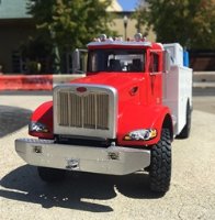
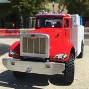
Thanks guys, we are making some progress - for today's adventure, the front bumper, winch, and PTO. So, as I always liked these PTO winches and bumpers - the way they stick out looks tough to me. And, as this project has shifted into the realm of adding cool things I like, well, a big bumper with a PTO driven winch we added! How many U-joints??? all the U-joints!!!! Nothing electronic or hydraulic on this rig! Thankfully the junk box is deep 😀 So, what is going on here? - well, as you can see, in went a bumper, chassis rails, winch, and PTO shaft! good. The bumper needs to step down from the chassis, so the hood can tilt forward, which is fine. Then, make up a winch - using left over resin wheel hubs - fine. Then using a cut up driveshaft from a 1/35 MRAP, make the drive shaft for the PTO. Still going fine! Then, install on chassis - keeping it level, and keeping the holes for the hood hinge pins open, while keeping the PTO drive shaft above the front axle - as seen in the lower right. Not easy, but worked out as well as could be hoped. Woo hoo! good to go! 😀 Then - just to be sure, take another quick glance at the prototypes....and...realize - uhhh, this is not good - it's ok, but not good. As I scratch built the winch, well, shoot - I made the opening in the bumper for it too deep - which meant the front bumper stepped down a bit dramatically (as shown in the lower left pic, with the dashed red oval). Still ok - looked pretty good while making it - even with those fancy pants tapers headed toward the fenders! equal and level! Then - actually look at it - and well, that deep bumper, fancy or not - just looked wrong. I didn't realize exactly how bad this looked until this morning when I looked again - nope - I can't go for that 😄 So, out came the razor saw - and to cutting we went. The good news is that this model, for the most part, isn't particularly fragile, so, held the chassis firmly in one hand and the razor saw in the other and off came the lower portion of the front bumper, winch and winch mount. And now, a better bumper! Still a brute, but a bit more convincing! Despite my hacking away, the bumper and the parts I wanted to stay put did so. Inside the red dashed oval you can see the PTO driveshaft. I added some shackles and mounting points. In the pic on the right, you can see how the frame rails step down . This was done to allow some clearance for the hood to functionally hinge, and to rest on the frame rails, and to clear the winch. Above, you can see the hood tilts and rests on the chassis rails as I want it to. You also see some of the bits I added to the engine. Speaking of the engine, the hood covers it with some clearance, which is good - but, for the longest time, it would not rest flush against the cab when tilted back. I eventually figured out that maybe like an MFH kit, the slightest bit of misalignment seems to get amplified with moving parts. So, out came the file, sanding sticks, and some more evergreen and glue. Good times. The upside is that after several tries I got it to line up. Oh, and how many bolts and rivets?? All the bolts and rivets!! Tediously, not all of them just yet! I can't mount the bed winches yet, as I'm still waiting for that 1/12 scale motorcycle chain to arrive, which will hopefully serve as my chain drive. I might do the cab interior next, and then on to the bed, or at least as much as I can do without mounting the winches. I think I can do this because the gin pole truck beds I've looked at have two parts - one with winches and hardware, and the other the gin poles, roller and so on. Ok gents, Happy model building, cheers, Nick
-
Nice and clean work! looking good 😀
-
Another big GM beast! Nice, and your engine yard, yes! absolutely worth keeping - you never know....lol - as I try and convince myself to toss old sprues..."I'll never need this...." 😄
-
Bravo on the chassis! Now you're just showing off - making it look easy 😄
-
Looking forward to seeing how you tie this together! Cheers Nick
-
Peugeot 405T 16GR Dakar - 1/24 Tamiya
Stickframe replied to bradeq's topic in Work In Progress - Vehicles
The suspension is looking really good! Cheers Nick -
AMT '65 lowrider Grand Prix
Stickframe replied to Pete in Lincs's topic in Work In Progress - Vehicles
Hi Pete, Hmm - rattle can, air brush - or leave it primer, matte black? with some glossy black rims, small chrome hubcaps and raised white letters on the tires? - or not!😄 The wrap around bumper looks the part, and yes, the paint on the exhaust did the trick, as the pipes no longer look molded in place! Cheers Nick -
Well guys, Billy big rig here again - Joroen, well, you were absolutely right - I did go ahead and glue the engine in - and then, embark upon a remarkably unpleasant task - the exhaust. For whatever reason, I concluded that this should be built in what amounts to a reasonably convincing fashion - which means, parts shouldn't touch where they shouldn't, such as exhaust pipes and drivelines - seems fair enough. Unhappily this was much easier said than done. Just one big, hot, tedious mess!! Adding to this, rather than just scratching a new exhaust, I unwisely concluded that it would be a better idea to "just" adapt the kit parts.....but as you will see, it's done: And here you have one sassy looking big rig! piece of cake....no - it wasn't. I added and removed both sides of the exhaust and those stacks several times. Inside the red circle, you can just see some light between the driveline and the pipes! Above you can sort of see how this works out. The reason this was such a headache? As this is a straight six engine, the exhaust comes out of the engine with a single pipe, then transfers via crossover to the two stacks - en route, it is strikingly close to my front axle driveshaft, which means in the center, there is now a "U" shaped crossover pipe, made from old sprue material. Next, the routing from under the truck to the stacks, which is, of course, not a straight shot - it is off-set to allow room for fuel and DEF tanks, and a battery box....perfect. In any event it's done. Next, of course I had to go back on my earlier thinking - and concluded that while pretty cool looking, the "shorty" bed wouldn't cut it. So, a guy went ahead and cut the rear of the frame off, removed the rear driveshaft, and extended the chassis rails and made a new driveshaft: Ahh - a real winch truck! The two vertical pencil marks on the chassis show the two sides of my original cut and fill! Back to Billy really-big rig! In the mean time, I added to the engine, which I'll show later. It turns out that aside from being six cylinders and turbo charged, the likely a Cummins engine, not a Caterpillar, that comes with the kit is not at all like the newer Paccar engine...great. I can live with that. But, also worked on the front steering, which went relatively smoothly: Above, you can see I went ahead and added a pitman arm (not sure if it's called that on a big truck?) to the steering gear, then added what looks like a short drag link to the knuckle, and then, a drag link connecting both front wheels - and it works remarkably well 😀 Then - back to the bed. It seemed like adding a big oil field winch was the right thing to do. I purchased a big single and a smaller dual winch from KFS when they were closing the old site - as the song goes "it's now or never" so, in the big one has been dry fit: In the spirit of the rest of this, another wise conclusion - If a winch is going in, why not build a chain drive PTO?? another easy task - lol. It turns out many oil field trucks run these big Tulsa winches, which are run off of a PTO(power takeoff), from the transmission to a chain drive. So, in went a PTO connection at the transfer case and a small, operable U-joint. I haven't added the same to the rear yet. For now, the plan is to use a 1/12 scale motorcycle chain to connect them. I order one from Spotmodel. Funny thing, it could arrive next week or next month! I eyeballed a resin part - and guessed it might work, and if not, well, I'll make it work - fingers crossed! Thanks for having a look Cheers Nick
-
Alfa Romeo 8 C 2300 - 1/12 - Italieri
Stickframe replied to bosscat's topic in Work In Progress - Vehicles
Hello - thank you for providing a really interesting introduction. I'll watch your build, as I have been tempted several times to buy this kit - sort of a two for one - we get yo see your project come together and maybe make a decision about buying the kit too! Cheers Nick -
Hello gents - all the good eating! all of it!! 😄 As some of you might have been able to gather, I work from home - so, one hand it's great - obvious enough why, but on the other - being at home always can get a bit old! Thankfully I do lots of zoom meetings, and my clients are far away, so every now and then I'll fly off to Texas or New York to project sites, and once a month drive up to Sacramento for a client meeting - they insist on in person - not sure why, it's a long drive (about 2hrs each way) and it's obvious enough that zoom works. But, when not doing that, I make it a point to go out for a walk every day - sometimes for lunch, other times, just to get out and move. And, as you have seen in various posts, I often see relevant material for a quick picture, like this: This glorious photo on the left is of a Kenworth concrete mixer, featuring the Hendrickson rear end. This doesn't say too much about it's flexibility, but it does suggest they can carry some weight! I did some research and found one cubic yard of concrete weighs about 4,050 pounds, and mixers carry 8-10 yards, so the load weight is between about 32,400 and 40,500 lbs or about 14,700kg to 18,400kg. As I am not a big truck expert, I can't say if that is a lot of weight or not, but, I can say that in my colorful youth I worked in construction, and have shoveled, wheel barrowed, and pumped lots of concrete, and can say with clarity - it is heavy!! And, the other photo is of a Paccar engine in a Peterbilt tractor, likely a 348. Unhappily for my, the model kit includes a big CAT engine - which is indeed a mighty beast, but not right for what I'm doing - so I can report there are several differences between the two. For my purposes I am focusing on getting the turbo routing correct, and changing from two external air filters, to one interior. In addition, because I cut up the hood/bonnet, and grill, I needed to cut up the radiator and fan to make them smaller, build a new fan shroud and reroute the radiator and turbo intercooler plumbing. This was not difficult per se, but it was slow going, and required lots of dry fitting and reworking: I'm sorry about the lack of contrast in these images. The glossy black kit parts just merge into a black mass. The model engine is nice enough, but a bit light on detail, which might be fine - I'll add some tubes and wires eventually, but for now the goal was to get it all to fit together. By this, I'm referring to getting the hood to tilt, locating the cab so it's a moderately close fit, locating the transfer case - and so on. Like noted already, this was not a strictly complicated series of tasks - but, did require numerous dry-fits, adapting kit parts and building new ones to tie this mess together!! So far so good. I decided to post now, because next on the list is routing the exhaust pipes - which now must be located above the front driveshaft (as someone, decided it would be a good idea to make this a 6x6), and under the shaft connecting the transmission to the transfer case. Hmmmm. Making this more of a challenge, I am considering making this a winch truck with gin poles. To make the winches work, a secondary driveshaft is run from the front tandem axle forward toward the cab where the winches are mounted. It's a PTO (power takeoff) that powers the winches, via chain drive! how's that for crazy? I debated making some sort of a load for the bed - a drill rig? crane? anything, but concluded that if this were my truck, I might like the flexibility that comes with a flat bed. This of course raises other problems, a guy should have mounted the tandems further back on the chassis, and it seems that gin pole trucks have conventional walking beams or giant springs packs....yeah, I going to go ahead and pretend not to notice those subtle points, and carry on! 😄 On with some progress: The foam sanding block proved useful for this little test - you can see the rear suspension doing it's thing! the walking beams pivot as hoped 😓😄 And, the other way too! Just like a real vehicle, the long driveshafts have slip joints (fake splined yokes) and those sassy U-joints! I'm glad to report no binding, and easy movement - whew!! I'll add the steering gear up front, which will have a pitman arm and drag link, tying to a bracket I need to install on the knuckle right next to the ball joint on the left front wheel - from there a drag link across to the other side. I'm not looking forward to this. I'm sorry I forgot to take a pic of the bracket that the transfer case hangs from. It took some time to make, and has a good and connection to the chassis. I also figured out the aforementioned torsion rods, don't have extra arms - apparently they are just controlled in the bushings - ok then. I'm still pondering where to glue the motor in place right now or not. I don't mind painting while in-frame (heck in real life, guys rebuild engines in frame!) so I might just glue it in - this will allow me to get that exhaust resolved a bit more easily - maybe I'll take it out one last time to string some hoses and wires? Not sure yet. Ok, that's my report - thanks for having a look Cheers Nick


