

albertross
-
Posts
34 -
Joined
-
Last visited
Recent Profile Visitors


albertross's Achievements
")
Newbie (1/9)
41
Reputation
-

DBR9 Wheels - with a bit of a how to CAD
albertross replied to albertross's topic in 3D Printing Basics
Super cool whatever they are from, and the info about profile and the valve is all super useful. Thanks again -
DBR9 Wheels - with a bit of a how to CAD
albertross replied to albertross's topic in 3D Printing Basics
There is some great work being done on this site. @Fritag hawks are really showing what can be achieved. Been distracted by a push bike rebuild and summer league hockey - so not much done . Love that flame finish on your guitar btw. All the best David -
DBR9 Wheels - with a bit of a how to CAD
albertross replied to albertross's topic in 3D Printing Basics
Absolutely incredible , thank you so much. Can I ask how and why you have a wheel? All the Best David -
DBR9 Wheels - with a bit of a how to CAD
albertross replied to albertross's topic in 3D Printing Basics
No worries, @Sabrejet i have done some test prints, shape of the tyre is a bit off but spoke work ok. Will look forward to some images. KR David -
DBR9 Wheels - with a bit of a how to CAD
albertross replied to albertross's topic in 3D Printing Basics
Hi Sabrejet, I have no clue. Would it be possible to post an image please. The article in Racecar Engineering stated the wheels were designed specially for the car - unlikely two sets of tooling were generated for a run of 17 chassis. The tool may have been moved if it was Aston owned. Will do a bit more digging. KR David -
DBR9 Wheels - with a bit of a how to CAD
albertross replied to albertross's topic in 3D Printing Basics
So as promised... Using another model of an OZ Ultraleggera rim from GRAB cad i Created a profile to revolve.. I only used the outside profile, the spoke profile is created by my MK1 eyeball and reference to the images on ROFGO. I then did a complete revolve to create this solid. For reference the dotted line is one of the datum planes Recreating my sketch from before using the datum plane, you'll notice some difference in the dims if u look closely - this is the final iteration. Then doing an extrude too (the highlighted) face i cut away the spokes The random 320 circle on the sketch allows me to generate a second extrusion to clear away the rest of the material. After cleaning up added the fillets to the ribs using a variable ratio fillet as well as the through holes. Our final profile looks like this I then dumped into fusion to complete a render. I did do a quick test print, but if anyone is interested I will show how I created the complete assembly... An image of the front wheel with a rear tyre... don't ask compared to the Airfix... -
DBR9 Wheels - with a bit of a how to CAD
albertross replied to albertross's topic in 3D Printing Basics
So the first thing i do is upload an image into autocad - you can use fusion to do the same. I then set about scaling the image to a 1: 1 representation. On this project for me this made sense as I have designed disc bells and centre locks so I was able to roughly gauge along with the rim and tyre OD to make a educated guess. I achieve this by drawing a number of circles to generate a nominal centre position, even the best photos are not likely to be completely square on, taking some measurements and then calculate the scaling factor for the photo. Once scaled I add a few lines to take some measurements - once again this really only gives you a staring point. So u can see I have sketched on a few lines ,taken some angle and intersect measurements - the extended lines for the spokes... Once we have these nominal dims we can start working up our sketches in 3D. I will now revert to the rear wheel as I an unfortunate crash meant I lost some dev work. Here is the sketch I created, a lot of this is trial and error, but this wheel went a lot quicker than the front. It took about three iterations to get to this point. The process was to generate a simple 2D file from the 3d model then overlay the designed part over our original layout. The orange line (just visible) shows us how close we are...(or not). On this iteration I was happy with the result. We are now able to create the final wheel. KR David -
HI All, Was doing a bit of research on the aforementioned DBR9 and stumbled across this excellent build article. Having read @JuanjoDominguez build he mentioned about the wheels not being 'the best' so i did a little research as I thought these would be excellent candidates for 3D printing. Thus the worm hole opened... I hope Juanjo doesn't mind me reusing his image for illustration purposes. The image shows a front and rear. You can see the the work he has done to remove mould misalignment. In looking for images i came across the Rofgo website. Just google Rofgo Collection, they have some excellent images of 007 & 009 including detail shots of the wheels. The below are snippets just a few of those images. Rofgo is mostly a collection of Gulf liveried racing cars Front Left 009 Rear Right 009 It immediately jumped out at me that the whilst the wheels in the kit are fairly similar the spoke pattern is actually a little different. The front has 2 corner rads on one cut out, whilst the rear has a single rad. Further research was required. From the images and an on line article from Racecar Engineering wheel size was determined as DIA 18" front and rear, width is 12,5" front and 13" rear. Tyre sizes were 31/71-18 rear and 30/65-18 on the front. A quick trawl of Michelin technical catalogue gave up the necessary information for the 31/71-18 As we can see the tyre code relates to the sizing. So 31 is a reference to the tread width 31 - 310mm and the 71 a reference to the OD - 710mm & 18 for 18 " wheel simple stuff. The info for the front tyre showed this carried through. This still didn't get me anywhere near the actual tyre profile the images showed it was quite detailed. So off to GRABCAD I went. (A very useful resource of free 3D models but you do have to register) where I found a model of a tyre. I can provide a link if required... I was lucky enough to find a smaller wheel of similar design that I pillaged for the rim detail. Next Post I'll outline how I schemed the parts up, but below is a quick spoiler..... All the Best David
-
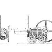
I wont intrude on your thread too much - Midland Railway Baldwin - 1900
-
Hey John, Your probably going to be looking at 3D paths as a minimum and probably also some surfacing. If you look for tutorials based at creating 3D sketches this may be a good starting point. I'm very much a solids man, so little use on this topic! All the Best David
-
How to do canopy frames and panel lines in Fusion 360?
albertross replied to zebra's topic in 3D Printing Chat
So selecting sweep from the create pull down menu We first select the profile we wish to sweep. So obviously we choose our triangle to create an indentation. (I have not printed using this style of recess any opinions on the matter would be interesting) Hopefully you can see that profile is highlighted blue in the sweep dialogue box, and that the actual profile now it is selected is also blue. So now we have the profile selected it is time to choose a path to sweep around. In this instance we are going to use sketch one To make this visible (if it isn't already) select the correct sketch in the sketch tree in your browser flyout and press the v key (keyboard short cut) Select path in the sweep dialogue box and then select the profile. Depending on your settings you will probably need to change the operation setting to cut. When all this has been selected you should get the above representation of what is about to transpire. This is all good, but I don't want to actually have a groove in the bottom face. Therefore back to the Sweep dialogue box. Here we can de select the chain tick box (Below path) We can now de-select the lower line giving us the following result. Neat huh, so now we are ready to rock and and roll and hit the magic ok button to accept the operation. With a little luck should end up with this. (exaggerated a little for clarity). Hope some of the above is useful. Don't forget there are many workflows to achieve the same result. This is just my preferred method. All the best David -
How to do canopy frames and panel lines in Fusion 360?
albertross replied to zebra's topic in 3D Printing Chat
So here we go how to create a sweep in Fusion for generating panel line / split. I'll use a similar shape to the mag cover. Firstly we create our base sketch. For simplicity I've made the base shape solid. We will re use this sketch later for the sweep. Notice the lines are all black, indicating the sketch is fully constrained. Also note the vertical constraint between the arc centre and the origin point which is the mid point of the bottom line. Also what you should be aware of is that every dimension has a unique identifier. This information can be re-used later on. For example the 20.00 dimension is d1 (NB) Once we have completed our sketch I extruded the profile equally from the mid-plane. We now create a sketch on our xz plane. You could of course select the face. This is important as the plane and our original sketch our related. With our plane selected we now create the profile we want to sweep. This will generate our panel line. On the sketch you can see the 9.75 dimension has an fx in front of it. This because I am using an equation to generate this position. I have referenced d1 to create our depth. This means if we change d1 to 21.00 the panel line sketch is related and will move with the modification and not fail. Below is the simple equation Now that we have completed the sketch we need to create the sweep. TBC -
How to do canopy frames and panel lines in Fusion 360?
albertross replied to zebra's topic in 3D Printing Chat
Mike if you are really interested i could perhaps run a tutorial over teams or something similar? Need to find a file sharing site to post images... still haven't recovered from photobuckets policy change -
How to do canopy frames and panel lines in Fusion 360?
albertross replied to zebra's topic in 3D Printing Chat
Whilst splitting is certainly an option I would advocate creating a sweep. Very versatile and can re use existing geometry. Print looks great. BTW -
Hi @Locomotion seeing your interests lie in the steam area will be 3d printing some of my own parts (hopefully) for a 7mm Midland Railway Baldwin. Will share some info soon.


