Search the Community
Showing results for tags 'Thunder Model'.
Found 13 results
-
Seems I got a bit sidetracked from the Bergepanther for a little while. The kit here is Thunder Model BL 7.2-inch Howitzer. It goes together very nice and is simple enough to build it in a reasonably short time - took me a week or so. Since there's no aftermarket for this kit anyways, I decided to go pretty much building it out of the box and didn't bother myself to correct all the inaccuracies the kit has. If you observe the box art, even there are many details wrong - most prominent of these are correct with the kit itself though. Most of the PE you see, came out of the kit and I only added a few details here and there. The kit builds into a pretty impressive size of an artillery piece with the oversized wheels being the most prominent part of it. The length of it is the same as the Bergepanther with a spade. The howitzer came with couple of huge ramps which were there to at least somewhat deal with the violent recoil the gun had. I have read that these weren't always enough and in some cases the gun jumped over these when fired. The ramps are present in the kit as well but are poorly executed so I took a bit more liberty there to make these half way decent. To prevent the most obvious question with the subject, then no - there's no Scammell tractor to go with it. Maybe some day, but for now it will be just the gun. Cheers! Kristjan
- 1 reply
-
- 14
-

-
- 1:35
- Thunder Model
- (and 1 more)
-
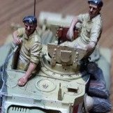
 LRDG F30 Patrol Truck (35306) With Ordnance 37mm Mk.I Bofors Gun 1:35 Thunder Model via Albion Alloys The Long-Range Desert Group (LRDG) are a historically significant fighting force that operated in North Africa during WWII deep in the desert, and often far behind enemy lines, using stripped down and augmented vehicles to travel to and from their destinations. From 1941 the larger of the two vehicles used were Ford F30 Long Wheelbase Trucks, manufactured as Canadian Military Pattern (CMP), and stripped of everything that wouldn’t be of use in the desert, such as doors, body panels, windscreens and any creature comforts. They also had enlarged radiators, raised and strengthened suspension, and a condenser system that recovered as much lost moisture from the system as possible. Unlike their predecessors, the Fords were 4X4, which almost doubled fuel consumption and reduced their effective range, but improved their rough ground handling. Some saw it as a backward step, and this was echoed by those in command, replacing them with Chevrolets starting in 1942, by which time most of the Fords were probably either written off or worn out by use, the abrasive nature of the locale, and the hot, dry climate there. The initial armament of the trucks consisted of Lewis guns and Boyes anti-tank rifles, adding Vickers .303 machine guns into the mix, and later widening the options with a 37mm Bofors anti-tank gun, which if fired forward would require the driving crew to duck and cover their ears if they wanted to survive with their hearing intact. The vehicles were fitted with six to eight mounts, but excluding the 37mm mount in the centre of the load bed, usually only three or four were in use at any one time during a mission. The trucks were equipped with compasses and radio-gear, and the crews usually carried a Lee Enfield rifle or similar, adding suitable quantities of water, food, ammunition, camouflage netting, and medical supplies in the event of injury to one or more of the crew members within their combat group. The water was just as important for refilling the radiator as it was for keeping the crews hydrated, and this became doubly important if the radiators were damaged during operations or had caught a bullet in combat, particularly if the repair wasn’t a good one. The trucks and men worked incredibly hard inflicting damage on the enemy, causing enemy troops to be re-assigned to guarding matériel and locations when they would have been otherwise employed in combat operations. Attrition of men and machines was severe, and many medals were awarded to LRDG operators, sadly sometimes posthumously, and their reputation continues to today, assisted by the efforts of the LRDG Preservation Society, who were active in assisting with the development of this kit and the others in the LRDG line, as can be seen on the box, and the history booklet. The Kit This is the second in a series of new toolings from Thunder Model that started with the basic truck, followed by this 37mm option. Each of these kits is available in a standard edition, or as a Limited bonus Edition for those wanting a little extra detail from the outset. This Limited Bonus Edition kit arrives in a flat rectangular box with a captive top-opening lid, and inside are five sprues of grey styrene, two frets of Photo-Etch (PE) brass, five pale grey resin wheels, two bags of 3D printed parts to build a pair of figures, add weapons and other details, two lengths of different gauge copper wire, a small sprue of clear parts, two pre-cut clear foil windscreens for the driver, a decal sheet, instruction booklet printed on glossy paper in black and white, plus a short 8-page history of the LRDG that has colour decal profiles on the back pages, which were created for them by AK Interactive. Detail is good and extends to the complete chassis, engine and the resin wheels have more detail than is possible with injection-moulded styrene. The additional parts are beautifully sculpted and have been printed at high resolution, although some of the casting block undersides are a bit on the rough side, but as they will end up in the bin anyway, it shouldn’t be a problem unless you plan on photographing the parts for a review or something. Construction begins with the engine and transmission, which is built up over six steps from a host of parts, followed by the transfer box over three more steps. The chassis rails are spaced apart by eight cross-rails, one of which has two additional parts added to the ends before installation, after which the engine and the newly built radiator are mated to the front, building the radiator from six parts plus two feeder hoses that link back to the engine. The exhaust system is an impressive seven parts, including a muffler midway, and an exhaust that exits to the side near the rear. The transfer box with reservoir is fixed into the centre of the chassis, making a drive-shaft from four parts that includes a universal joint, requiring no glue. The rear axle consists of two hubs with brake drums at the ends, and the bulbous differential off-centre of the axle, which is attached to the double-stack leaf-springs by twin U-bolts and corresponding nuts on either side. Small parts and linkages are applied around the axle, then the front axle is made in a similar manner, but with a shorter differential and single-stack leaf-springs, again attached to the axle via twin U-bolts on both sides. The hubs and short power-transfer couplings are built in a similar manner to the real thing, using seven parts including the brake drum per side. A steering linkage and six-part drive-shaft link the front axle to the transfer box, with a much longer five-part shaft heading to the rear, adding two small parts to the inner face of a toroidal structure on the aft face of the transfer box. A large four-part fuel tank runs down most of both sides on two L-brackets between the axles, adding a PE ring and styrene filler nozzle after drilling a bleed hole above the filler location. The complex shape of the cab floor is made from five parts, with a scrap diagram showing the correct location of the parts, then a pair of front wheel arches are made from three parts each, and glued to the sides of the floor with the help of another scrap diagram, adding four additional panels to the front, then making the headlights and two PE brackets further back on the arches. The seats are made from two cushions that are joined by a pair of C-shaped tubular frames, building two before fixing them in the cab floor, then adding driver controls in the centre console and pedals in the right-hand foot well. Behind the crew is a bulkhead with a fire extinguisher in the centre, with a decal on it and a PE log-book on the driver’s side, then adding two more PE brackets to the trailing side of the wheel arches. More decals are applied to the centre console, a PE strap is added to the extinguisher, and a three-part PE lozenge-shaped insert is glued to the top of the fuel tanks on both sides. A rifle cup and bracket are mounted in the rear of the cab as it is mated to the front of the chassis over the engine, adding support brackets for tread-plate steps on each side of the cab. A pair of 3D printed ducts are supplied to fit under the front arches, one for each arch, leading back into the vehicle. The bumper iron and two upstands with a top rail are mounted on the front of the vehicle, adding an overflow reservoir with PE bracket and decal inside the engine bay, plus bracket-ends on the chassis rails that are shown in a scrap diagram to assist with locating them. The steering column and linkage are threaded through the chassis from below, mounting a four-part box behind it, and another bracket with tread-plate on the opposite side. A retainer fixes the steering column to the dash so that the wheel can be fitted to the end, using a piece of 0.6mm wire as the base for the foil windscreen (there is a spare too), and creating frames to the sides that are each made from three PE parts for accuracy. A cylinder is fitted to the right side of the chassis in front of the fuel tank on a PE bracket, routing another length of 0.6mm wire to the top of the radiator for added realism. The load bed consists of a deformed I-shaped floor that needs some slots cutting into it, with short steps added to each side along with two arch inserts in grooves within, then fitting the sides to the bed, and adding the support structure beneath the floor, plus the corners and the tail-gate at the rear of the vehicle. The headboard has a 3.3mm length cut from the angled bar moulded into the inner surface, making good the area where the removal took place. A spare tyre is glued into the space behind the headboard, then the load bed is joined with the rest of the vehicle, finishing off the bed with PE brackets, hinges, rear light brackets with styrene light housings, and strapping, finishing the body by adding an optional triple weapons rack outboard of the co-driver’s position using PE clips and cups on the tread-plate. The 37mm Bofors gun is moulded as barrel with a hollow muzzle on its sled, to which the breech and elevation rack is added, mating with a six-part base, and locking it in position with the trunnions, whilst leaving the barrel free to pivot by not using glue – unless you want to. Controls for elevation and rotation are fitted along with a breech lever, then the completed gun has its highly-sloped splinter-shield made from four parts, and located on the weapon by four stand-off brackets. Additional PE splinter-guards are added to the bottom of the shield to prevent injury to the crews’ legs, and the gun is mated with the load bed by a raised platform that is built from four verticals, two of which are 3D printed, a platform and four diagonal supports, locking the gun in position with a short pin that pushes through a hole in the centre of the platform. This glues into the bed floor via the four slots cut earlier with the assistance of a scrap diagram that gives positional information. A travel lock is made from five PE parts plus short lengths of 0.5mm wire, and is glued to the bed floor behind the gun, wrapping the top parts around the barrel and closing the bracket with a PE wing-nut. The resin wheels are applied to the wheel hubs and fixed in position with small caps, then you have the choice of fitting a pair of PE sand-channels that have eight PE brackets down their length, and are secured to the sides of the load bed by parts labelled PE2. Limited Bonus Edition Parts As well as the ducts under the front arches and the centre sections of the gun platform, there are two crew figures that are wearing typical casual dress worn by the LRDG crews, consisting of light-weight clothing, and a head scarf held in place by an elasticated band, known as a Keffiyeh in the Middle East. There are also copious rifles and machine guns for the crew to stow in the vehicle, including an incredibly well-detailed Lewis gun, a pair of Lee Enfields for the rifle clips, and a Thompson with stick magazine, or Tommy gun as it was more colloquially known. There is also a revolver, a flare gun, machete, a large scabbard, and a few other small parts that are intended for the Lewis gun, although the standard instructions don’t show how they fit. There is a separate instruction diagram on Thunder Model’s site however, that we have reproduced below for your ease. Markings There are five decal options on the sheet, and the profiles have been penned by AK Interactive’s artists for Thunder Model, although there isn’t any information given about when or where these vehicles served, other than their vehicle numbers on the back of the load bed. From the box you can build one of the following: Decals are by Thunder Model’s usual partners, which means good registration, sharpness and colour density, with a thin gloss carrier film cut close to the printed areas. Conclusion This is a highly-detailed model of a vehicle that was used in support of the Allied North Africa campaign during WWII, driven and operated by very brave men. The fact that it also carries a big gun appeals even more (to me). Highly recommended. Available in the UK in all good model shops. Review sample courtesy of
 -
LRDG F30 Patrol Truck (35304) CMP in LRDG Service 1:35 Thunder Model via Albion Alloys The Long-Range Desert Group (LRDG) are a historically significant fighting force that operated in North Africa during WWII deep in the desert, and often far behind enemy lines, using stripped down and augmented vehicles to travel to and from their destinations. From 1941 the larger of the two vehicles used were Ford F30 Long Wheelbase Trucks, manufactured as Canadian Military Pattern (CMP), and stripped of everything that wouldn’t be of use in the desert, such as doors, body panels, windscreens and any creature comforts. They also had enlarged radiators, raised and strengthened suspension, and a condenser system that recovered as much lost moisture from the system as possible. Unlike their predecessors, the Fords were 4X4, which almost doubled fuel consumption and reduced their effective range, but improved their rough ground handling. Some saw it as a backward step, and this was echoed by those in command, replacing them with Chevrolets starting in 1942, by which time most of the Fords were probably either written off or worn out by use, the abrasive nature of the locale, and the hot, dry climate there. The initial armament of the trucks consisted of Lewis guns and Boyes anti-tank rifles, adding Vickers .303 machine guns into the mix, and later widening the options with a 37mm Bofors anti-tank gun, which if fired forward would require the driving crew to duck and cover their ears if they wanted to survive with their hearing intact. The vehicles were fitted with six to eight mounts, but excluding the 37mm mount in the centre of the load bed, usually only three or four were in use at any one time during a mission. The trucks were equipped with compasses and radio-gear, and the crews usually carried a Lee Enfield rifle or similar, adding suitable quantities of water, food, ammunition, camouflage netting, and medical supplies in the event of injury to one or more of the crew members within their combat group. The water was just as important for refilling the radiator as it was for keeping the crews hydrated, and this became doubly important if the radiators were damaged during operations or had caught a bullet in combat, particularly if the repair wasn’t a good one. The trucks and men worked incredibly hard inflicting damage on the enemy, causing enemy troops to be re-assigned to guarding matériel and locations when they would have been otherwise employed in combat operations. Attrition of men and machines was severe, and many medals were awarded to LRDG operators, sadly sometimes posthumously, and their reputation continues to today, assisted by the efforts of the LRDG Preservation Society, who were active in assisting with the development of this kit and the others in the LRDG line, as can be seen on the box, and the history booklet. The Kit This is the first in a series of new toolings from Thunder Model, starting with the basic truck, followed by the 37mm option, which we’ll be reviewing soon. Each of these kits is available in a standard edition, or as a Limited bonus Edition for those wanting a little extra detail from the outset. This standard edition kit arrives in a flat rectangular box with a captive top-opening lid, and inside are four sprues of grey styrene, two frets of Photo-Etch (PE) brass, five pale grey resin wheels, two lengths of different gauge copper wire, a small sprue of clear parts, two pre-cut clear foil windscreens for the driver, a decal sheet, instruction booklet printed on glossy paper in black and white, plus a short 8-page history of the LRDG that has colour decal profiles on the back pages, profiles that are repeated on separate sheets with a glossy surface, which were created for them by AK Interactive. Detail is good and extends to the complete chassis, engine and the resin wheels have more detail than is possible with injection-moulded styrene. Construction begins with the engine and transmission, which is built up over six steps from a host of parts, followed by the transfer box over three more steps. The chassis rails are spaced apart by eight cross-rails, one of which has two additional parts added to the ends before installation, after which the engine and the newly built radiator are mated to the front, building the radiator from six parts plus two feeder hoses that link back to the engine. The exhaust system is an impressive seven parts, including a muffler midway, and an exhaust that exits to the side near the rear. The transfer box with reservoir is fixed into the centre of the chassis, making a drive-shaft from four parts that includes a universal joint, requiring no glue. The rear axle consists of two hubs with brake drums at the ends, and the bulbous differential off-centre of the axle, which is attached to the double-stack leaf-springs by twin U-bolts and corresponding nuts on either side. Small parts and linkages are applied around the axle, then the front axle is made in a similar manner, but with a shorter differential and single-stack leaf-springs, again attached to the axle via twin U-bolts on both sides. The hubs and short power-transfer couplings are built in a similar manner to the real thing, using seven parts including the brake drum per side. A steering linkage and six-part drive-shaft link the front axle to the transfer box, with a much longer five-part shaft heading to the rear, adding two small parts to the inner face of a toroidal structure on the aft face of the transfer box. A large four-part fuel tank runs down most of both sides on two L-brackets between the axles, adding a PE ring and styrene filler nozzle after drilling a bleed hole above the filler location. The complex shape of the cab floor is made from five parts, with a scrap diagram showing the correct location of the parts, then a pair of front wheel arches are made from three parts each, and glued to the sides of the floor with the help of another scrap diagram, adding four additional panels to the front, then making the headlights and two PE brackets further back on the arches. The seats are made from two cushions that are joined by a pair of C-shaped tubular frames, building two before fixing them in the cab floor, then adding driver controls in the centre console and pedals in the right-hand foot well. Behind the crew is a bulkhead with a fire extinguisher in the centre, with a decal on it and a PE log-book on the driver’s side, then adding two more PE brackets to the trailing side of the wheel arches. More decals are applied to the centre console, a PE strap is added to the extinguisher, and a three-part PE lozenge-shaped insert is glued to the top of the fuel tanks on both sides. A rifle cup and bracket are mounted in the rear of the cab as it is mated to the front of the chassis over the engine, adding support brackets for tread-plate steps on each side of the cab. The bumper iron and two upstands with a top rail are mounted on the front of the vehicle, adding an overflow reservoir with PE bracket and decal inside the engine bay, plus bracket-ends on the chassis rails that are shown in a scrap diagram to assist with locating them. The steering column and linkage are threaded through the chassis from below, mounting a four-part box behind it, and another bracket with tread-plate on the opposite side. A retainer fixes the steering column to the dash so that the wheel can be fitted to the end, using a piece of 0.6mm wire as the base for the foil windscreen (there is a spare too), and creating frames to the sides that are each made from three PE parts for accuracy. A cylinder is fitted to the right side of the chassis in front of the fuel tank on a PE bracket, routing another length of 0.6mm wire to the top of the radiator for added realism. The load bed consists of a distorted I-shaped floor with short steps added to each side along with two arch inserts in grooves within, then fitting the sides to the bed, and adding the support structure beneath the floor, plus the corners and the tail-gate at the rear of the vehicle. A PE base-plate is glued to a marked position on the floor, adding styrene support rods to a post that glues into the hole in the base. A Lewis machine gun is built from three parts with a hollow muzzle and fixed to the top of the post, then the load bed is joined with the rest of the vehicle, finishing off the bed with PE brackets, hinges, rear light brackets with styrene light housings, and strapping, finishing the body by adding an optional triple weapons rack outboard of the co-driver’s position using PE clips and cups on the tread-plate. The resin wheels are applied to the wheel hubs and fixed in position with small caps, then you have the choice of fitting a pair of PE sand-channels that have eight PE brackets down their length, and are secured to the sides of the load bed by parts labelled PE30. Markings There are four decal options on the sheet, and the profiles have been penned by AK Interactive’s artists for Thunder Model, although there isn’t any information given about when or where these vehicles served, other than their vehicle numbers on the back of the load bed. From the box you can build one of the following: Decals are by Thunder Model’s usual partners, which means good registration, sharpness and colour density, with a thin gloss carrier film cut close to the printed areas. Conclusion This is a highly-detailed model of a vehicle that was used in support of the Allied North Africa campaign during WWII, driven and operated by very brave men. Highly recommended. Available in the UK in all good model shops. Review sample courtesy of
-
Hi all! My first "Ready for Inspection" after a lengthy but enjoyable process. For the nitty gritty details see the in-progress thread: As usual with these things, it turns out my grandpa was more of a driver and worked primarily with a light AA regiment! Regardless, this was a fun build with lots of detail and only a few pain points. The BL 7.2" howitzer was used from ~1942 until the early 1960s. Based on rebored WWI 8" guns, their most (in)famous gunner was Spike Milligan. His war memoirs brought this kit to life. The Scammell Pioneer was used as a tank transporter (with trailer), recovery vehicle, and artillery tractor both pre- and post-WW2. My build is a bit of a mash up, because although Thunder Model boxed the kit in a desert scheme, neither the gun or tractor come with decals for one. Your best bet is to go for a 1944/45 heavy regiment. So here I just used the markings from a vehicle used in Italy, 1943. There are a number of ancillary parts for the gun that can be seen in the in-progress thread. Not sure what to do with them as of now. I'm very happy with the figure (first one with eyes!) and of course he's hidden away in the cab. I am also happy with the dust effect on the windscreen, first time trying that. Biggest mess is the rear cloth canopy which got rather mangled and I did a rough job filling it. Criticisms and suggestions for improvements are welcome. I hope to eventually 1) replace the rear cloth 2) add a tarp covering the back half of the gun to cover up the optics, which should be stowed when in motion, and because most photos I've seen show such an arrangement. Looking out the window: It's a rather lengthy result: And the mangled rear end: More images on the Scalemates albums here: https://www.scalemates.com/profiles/mate.php?id=123123&p=albums&album=109445 https://www.scalemates.com/profiles/mate.php?id=123123&p=albums&album=110528
- 6 replies
-
- 23
-
-
- Thunder Model
- 1:35
- (and 1 more)
-
 As my grandpa on my father's side fought as an artilleryman in North Africa, WW2 British AFVs, especially the early types, have been my primary interest since returning to the hobby in 2022. In that time I've completed 16 1/35 AFV kits (see some of them on my scalemates wall https://www.scalemates.com/profiles/mate.php?id=123123&p=albums) but only one has actually been artillery, the Dragon 25-pdr and limber. As an expat in the US it's a bit prohibitive to get accurate armour resin kits shipped over, so I was glad to see Thunder Model re-released their 7.2" Howitzer alongside the Scammell Pioneer R100. After a careful watch of Nigel's Modelling Bench build of the howitzer (https://www.youtube.com/watch?v=4QsmMZuON6Y), I've started on it in earnest. So far I've run into much the same issues as he did. The instructions are mediocre at best. The parts are generally okay, but some of the locating pins do not fit their supposed locating holes. There is indeed a seam between the rivets of the gun mount, but frankly I do not have the patience to tackle that, so I will just try to avoid it when it comes to weathering. The chassis doesn't have a great fit. The photoetch is quite thick in parts and honestly if I had not recently bought a bender, I would not have bothered with the parts that have plastic alternates. The wheels are good enough for my purposes. The barrel also cleaned up reasonably well. Currently the kit is in reality in 5 parts (limber, gun mount, gun, 2x wheels) for painting. I expect some filler will be needed on the chassis after priming shows gaps. Thanks to Nigel's video I managed to get the gunsight mounted without fouling the left wheel (I hope). Planned paint scheme is desert, so Light Stone overall. I may add some black, olive or slate colours that were often used in a ripple effect on barrels. I don't have any photographic reference for a 7.2" in Africa though, so it will mostly be artistic license. If anybody does have such a reference, it would be most welcome.
 -
German Bergepanzer Hetzer Late with 2cm Flak (35105) 1:35 Thunder Model via Albion Alloys The Hetzer was a highly successful tank destroyer that was based upon the chassis of the Czech P38(t), which mounted a powerful 75mm gun in the glacis with limited traverse capability, obviating the need for a turret and thereby reducing its profile, but requiring the driver to slew the vehicle for re-targeting at times. The Bergepanzer variant was fitted with a smooth glacis with no gun port or mantlet, and it had an open top for ease of ingress by the crew, who would be in and out connecting towing ropes etc. to any vehicle in distress, possibly whilst still under fire. Due to its designation as a "light" recovery vehicle its use was limited to an extent, and only 170 were built in total, with later models benefitting from experience in the field, and from schürzen side-skirts that helped dissipate the blast of shaped charges that were in common use by the Allies in the later part of the war. Prototypes of other uses were designed as the war progressed towards its conclusion, which included an mobile anti-aircraft vehicle with a 20mm Flak mount in the centre of the open hull, leaving space for the crew to work around it when not in use. It was an open-topped vehicle that would need a canvas tarpaulin during foul weather to keep it from filling up with water and making the crew extremely uncomfortable at the very least. As far as records go, only one example was made before the end of the war, as the capability of German industry was eroded by almost continuous bombing day and night, worsened in due course by the steady advance of the Allies through their industrial heartland. The Kit This is a variant on Thunder Model's original Bergepanzer Hetzer late, which has been released with different parts to bring a total of six boxings including this one, which was preceded by a Limited Special edition boxing that included some upgrades such as a full engine compartment at the rear of the vehicle and additional PE. The kit arrives in a top-opening box with a captive lid, opening to reveal eleven sprues of grey styrene in various shades, plus a ziplock bag that contains three frets of Photo-Etch (PE), a length of brass wire and braided cord. Two versions of the same decal sheet are also found in the Ziploc bag, one with an elfbein (light buff) background to the instruments, the other with a clear carrier film only. The instructions are printed on an A4 booklet in portrait with greyscale isometric views, and the painting guide is printed on glossy stock in full colour. The instruction booklet that comes with the kit is suitable for both the special edition that came with a sprue of engine parts and extra PE, so for this standard edition you start on step 5. Due to the open top, quite a lot of the interior will be on display, so it begins with the addition of dozens of tiny rivets around the inside of the hull around the final drive housing, followed by the suspension units with their large wheels plus various suspension parts that are added all around before the link-and-length track is built up around the road wheels and drive sprocket. The rear bulkhead is slotted into the hull beforehand along with the optional towing cables, lifting eyes and towing hooks. The transmission box is constructed over several steps from many parts before it is dropped into the front of the hull, adding some control-rods made from the wire that is supplied with the kit. The driver's seat is made from four parts that includes a back-rest, and this is positioned with PE pedals and controls that are glued into the left side in front of the seat, adding a large PE lever to the left side of the transmission tunnel. The firewall bulkhead is detailed with PE and styrene parts, and is fitted to separate the empty engine bay from the crew compartment, inserting a drive-shaft between it and the end of the transmission as it is slotted in. Before the upper hull can be fitted, the 20mm Flak gun and its mount must be prepared and built, with painting almost a necessity before you close the hull around it. The barrel and breech are moulded as one, fitting a conical muzzle brake and the top detail of the breech to complete the assembly, then the mount is made over several steps with PE parts for the elevation mechanism, which includes mating the inner portion without the use of glue, and joining it to the circular base-plate before the ancillary parts, including the sighting mechanism and seats, can be added. A small splinter-shield is mounted on an L-shaped bracket in front of the gunner’s position on the right, with a ring-and-bead and backup tubular sight fixed to the breech near the gunner’s eyeline. The completed gun is then mounted on the rotation ring, held in position by a large circular platter that glues to the underside of the gun’s ring platform, gluing the outer edge of the ring to the base, which is made from two parts set one on top of the other. The upper hull is open at the top as already mentioned, and the inner lip is festooned with ammo boxes on PE brackets and in cages on both sides and at the front, using styrene for the ammo cans themselves. Several brackets are added to the exterior lip of the hull, including a vision slit for the driver and the convoy light over the left mudguard, the brackets destined to hold extra equipment later in the build. The flak assembly is mounted in the centre of the lower hull, placing another PE rack with two styrene ammo cans where a bow gunner’s seat would have been on the right, after which the upper hull can be lowered over the gun, taking care not to damage the barrel or other delicate parts of the gun as you do. An exhaust, jack and winch assembly are made up, then the panel for the engine deck at the rear is built, which is constructed by adding an inverted T-shape with PE grille in the centre, and fitting the two access panels at the top left and right, the winch cable exiting from the right side. Various PE brackets are used, and the rear fenders are fixed to the hull sides, mounting the Pioneer tools and the bergepanzer specific tools over the slab sides, including the crane arm that is collapsed for transport on the left side with the diagram over the page, and fixing a length of spare track along the top on a PE bracket at the back of the roof with separate bolt heads, plus a curved PE bracket to support the exhaust assembly. Markings There are two markings options in the box, but as neither have any stencils applied, there are just a few decals that includes two crosses and instrument dial decals with a clear background and another with a tan background that is intended to mimic Elfbein. Although no details are given about the location and operation of the vehicles, probably because it is unlikely to have seen service, from the box you can build one of the following: The decals are printed in duplicate with the alternative background to the dials on one sheet, giving you four crosses in total. They are small and printed well enough to be useful for the task at hand. Conclusion This is a nicely detailed model of an unusual Hetzer, with a pair of nicely printed late-war schemes and some useful PE parts, brass wire, and cord to round out the package. Highly recommended. Available in the UK in all good model shops. Review sample courtesy of
-
Morris Bofors C9/B Late (35209) 1:35 Thunder Model via Albion Alloys During WWII, after crews of light artillery in transport began firing their weapons from the back of the trucks they were carried upon to save dismounting and increase the speed that they could relocate, the British Military commissioned Morris Motors to create a new mounted weapon that would utilise the chassis of the successful C8 Quad Tractor that was used to tow heavy artillery throughout the war. The official specification was Carrier, SP, 4x4, 40 mm AA, but it was more commonly known as the Morris C9/B, which shared the engine bay cowling up to the windscreen, but differed massively aft of there, mounting a Bofors 40 mm L/60 gun, which was the pre-eminent 40mm auto-cannon of the day, originating in Sweden, but proliferated around the world by the end of WWII. Its 40mm shells were effective up to 23,500 feet in the anti-aircraft role, and it could fire over 120 rounds a minute if it could be fed with ammunition quickly enough. The type was made in large numbers, serving in Europe in large quantities, and it was especially useful in North Africa where its tracer rounds were also inventively used to designate tracks across minefields and indicate lines of attack where it was unclear. The were also unloaded early on D-Day, providing ad hoc air defence that could be deployed and moved quickly without the delays inherent with unlimbering towed artillery. It was also used to provide fire support during the Allied ground advances through France and into Germany, where its 40mm rounds would devastate all but the most heavily armoured targets, especially personnel and softskin vehicles, which would be shredded by the weight of fire. Later in the war they were used on the south coast of Britain as part of the defence against the new terror weapon the V-1 flying bomb that the Nazis were launching from France as an overly-optimistic last-ditch attempt to turn the tide of war. Of course, once they were pushed back from the coastal areas, the V-1 threat to London and the surrounding area evaporated, to be replaced briefly by the ballistic V-2, against which there was no defence. The Kit This is a new tooling from Thunder Model, filling another gap in the WWII British armour and softskin range, and it’s excellent news. The kit arrives in a shallow top-opening box with a captive lid, and inside are eleven sprues of grey styrene, a small clear sprue, a Ziploc bag of five resin tyres, another bag with three sheets of Photo-Etch (PE) brass and a sheet of decals inside, a length of copper wire, the instruction booklet with errata sheet tucked inside, and a high-gloss colour sheet with painting and marking profiles on both sides, created for them by AK Interactive, using their acrylic and RealColor paint codes to assist with finishing your model. Detail is excellent, which includes the depiction of the engine and chassis, and with the addition of the PE and the resin tyres, it’s unlikely you’ll need to splash out on aftermarket unless you’re in need of extra detail above-and-beyond usual levels. Construction begins with the engine, which is a highly detailed assembly of over thirty parts, including PE and styrene to recreate the block, gearbox, and the transmission. The completed motor is trapped between two sub-frame rails, with a cross-brace at the front, and an asymmetric section at the narrower rear end. The main chassis rails are double-thickness to avoid sink-marks, and there are three substantial cross-members toward the rear, and another small frame at the front that is joined by more cross-members, then it accepts the engine sub-frame so that the front axle can be built under the engine, mounted beneath the rails on leaf-springs, the axle itself highly detailed, utilising some parts without glue that give it the possibility of workable wheels. The rear axle is similarly made, and all axles have large drum-assemblies at each end in preparation for the tyres that will be fitted at the end. The axles are held against the leaf springs by strong U-bolts, which are made from lengths of wire that is included in the kit. Many detail parts are fitted on and around the axles to stabilise the suspension and link the steering to the front axle, including a long drive-shaft that sends power to the rear axle, with a short one providing power to the front axle on this 4x4 vehicle. The exhaust is a long slender part with a narrow muffler that is threaded under the chassis to the engine manifold, and exits at the left side of the vehicle around the midpoint. The next step is to create the open cab, which is made from angular panels, starting with the lower parts of the structure, which has stowage boxes under the three seats, that attach via two C-shaped tubular frames underneath, the rear leg supporting the backrest, which can be folded flat. A fairing is made over the rear of the engine, and the simple dashboard has six decals applied to represent the white dial legends and stencils on the transmission hump. More details are added, including foot pedals, levers, a hose on the engine, and a substantial cross-member that mates with the rear of the cab floor, after which the steering column and wheel are fixed in the cab, and an airbox with linked hose that is surprisingly located within the cab. The space in front of the cab shows the front of the engine at this stage, which has the radiator, fairing, feeder hoses and radiator cap, without gluing one lower side of the radiator to the chassis. A PE cooling fan has its blades twisted to an angle before it is installed at the front of the engine and behind the radiator. The cowling is a three-part affair, and the right-hand section needs a groove filed on one side so that the steering wheel clears it sufficiently, topping off the bonnet with a single part, which prevents modelling the vehicle with the engine exposed unless you either make new cowling parts, wait for a PE set with cowling parts, or carry out surgery on the kit parts. The Bofors installation is attached to the main chassis on its own sub-frame, which is made first, with the turret ring in the centre of a long assembly that straddles the main chassis. It is joined by a pair of stepped outriggers to the rear, and the completed main area of the floor is joined to the chassis, adding a set of pioneer tools on a lower panel, held in position by a pair of straps that are secured by large wingnuts. The rear “bumper” is also a support for the ends of the raised outriggers, and is completed over two steps, after which you find out why it needed to be strong, as there are ten large crates of ammo built from six parts each, plus PE shackles and carry-handles. They are stacked up on the outriggers, and can be locked down by fitting brackets that latch on the handles, snugged down by more wingnuts, as shown in a scrap diagram. Stowage boxes are fitted under the rear of the outriggers, with separate door parts, and a further two smaller ammo crates are supplied to fill any empty space on the ends of the outriggers. Two fuel tanks are made from four parts each, and are suspended from the sides of the chassis on PE brackets that are folded up from straight straps, with a diagram showing their shape from the front. You’ll need to bend four of these, so it may be worthwhile creating a styrene jig from sheet or strip to help you fold them to a uniform shape. They are each protected at the sides by a box with an open bottom, which are folded up from two L-shaped PE parts, covering the filler hatch with a PE lid that is folded into a shallow box, again with no bottom. Two more stowage boxes are fitted under the back of the front arches, and these too have separate doors. To keep the truck stable when firing, a set of support cones are deployed, but in transport mode, they are stowed on the front arches. They are built from a bucket-shaped part that is mounted on a three-layer circular dish, with a fold-down bracket holding them in position from front and rear, plus a pair of PE stops at the front of the arch to prevent them slipping off. The headlamps with clear lenses are attached either side of the radiator on the bumper, plugging into holes in the upper surface. The support cone mechanisms are made from two scissor-links that are chosen depending on whether you plan to pose your model in firing position or in transit. The same rods link the scissors together, with a pivot at the bottom that holds a circular dished plate in position for transit, adding the cone and foot if modelling them deployed. They fix to both sides of the chassis in front of the rear wheels, with the assembly pivoted to the side for transport to decrease the vehicle's width. Another support assembly is fixed under the rear of the load bed, and the last support fits in the centre of the front cross-brace in front of the radiator. The 40mm Bofors is surrounded by a tread-plated and sectioned floor, which is mounted on a tubular frame that rotates with the gun. The base is fixed to the frame first, adding the angular plates around the frame, then fitting the base for the gun in the centre along with some other small details and controls. The core of the gun breech is built from eight parts, then sandwiched between the two outer surfaces, adding an impressive styrene spring to the front that has been created with the use of slide-moulding, but take care removing it from the sprue, as a poor set of nippers could fracture the part. See my recent review of the GodHand Ultimate Nippers if you’re concerned. More detail parts are fitted to the breech and to the sides of the elevation track, gluing the barrel into the front of the breech, then adding recuperators under it, linked to the substantial trunnions, taking note of where not to glue so that the gun can pivot once completed. The assembly is then mated to the floor, and detailing proceeds, adding equipment, mechanisms, and controls to the weapon, plus a pair of two-layer splinter shields fixed to the front of the gun via dog-leg brackets, adding single-layer screens at an angle to the sides. Sighting equipment on a triangular frame is installed above the breech, and in slots in the splinter shield, giving the gunner a bicycle-style seat with shallow backrest, mounted to the left side of the floor, and filling the W-shaped PE rack (a template is found nearby) next to the gun’s shell feeder with a clip of 40mm rounds inserted. The PE ring-sights are fitted to the sighting mechanisms in tandem on both sides of the splinter shield, with a pair of small PE wingnuts giving the impression they’re holding them in place instead of super glue. Two styles of winding handles are supplied for the left side of the gun, finishing work on the weapon for a while. A spare barrel is carried on a rack that is fitted to the right side of the load area, moulded as a barrel with integral spring and separate muzzle that is attached to the rack by being fed through two brackets that are glued to the rack, and detailed with two tiny C-shaped handles near the centre. It mates to the outrigger on two tabs, and then there is a page of steps filled with small parts added around the vehicle, including PE mudflaps, various PE brackets and caps, a pair of rectangular tools on a PE shackle, and a short section of floor at the rear of the vehicle is also made from a sheet of PE. More PE is used in creating a fuel can storage rack, which holds three styrene cans with PE handles and separate fillers, fitting into the lower centre section of the chassis on the left at the same time as the gun mount is lowered into position. The flared muzzle of the gun’s barrel is left off until now, although if you plan to use the travel lock, you will need to leave it off until the barrel is slipped through the detailed part that pivots into a recess in the back of the floor when not in use. A protective cover is folded up from four PE parts and placed over the ammo feed if the gun is not in use, then almost as an afterthought the wheels are fitted to the finished model. The wheels are worthy of note, as Thunder Model have gone to the trouble of supplying resin wheels from the outset, which only need a little sanding to remove the remains of the link to the casting block on the lower side of the tread, offering much better detail than can usually be achieved with styrene parts that are often made from two halves, or a lamination of several layers for detailed tread patterns. Each wheel has a two-part hub cap added in the centre, and the spare tyre is shown hovering in space on the little diagram on the back inside page, which is why it feels like an afterthought. As to the location for the tyre, most pictures don’t show it anywhere on the vehicle, but several photos and some of the early renders of the kit when it was announced shows the tyre lodged between the engine cowling and the left front wheel arch. It is likely it would need a strap to hold it in position, which you could fabricate from tape, some left-over PE or lead foil. If you’d rather not have to adjust the instructions provided to correct it according to the errata sheet included in the instructions, you can download the revised instructions here. Markings There are two decal options on the small sheet, both of which have camouflage schemes applied to them. From the box you can build one of the following: 1st Infantry Division, Italy 1944 119th Light Anti-Aircraft Regiment, 15th Scottish Infantry Division, North West Europe, 1944 Decals are printed anonymously, and have good registration, sharpness and colour density, with a thin matt carrier film cut close to the printed areas. Conclusion This is a welcome addition to the range of British WWII AFV subjects available, and it should build into a well-detailed, impressive replica of this highly effective mobile anti-aircraft system that kept enemy attacks from reaching strategic areas under Allied control. Highly recommended. Available in the UK in all good model shops. Review sample courtesy of
-
 Thunder Model has released a 1/32nd Clarktor-6 airfield tractor - ref. 32001 Sources: https://www.thundermodel.com/US-Clarktor6-Mill33-Tug.html https://www.facebook.com/ThunderModel/posts/pfbid0YHGfojzXLDfa2c59PFGSbL6bw6cqaw5pb9aaVjToJu74AcHrnht9khMS1xBKn2z7l V.P.
 -
Hello. I'm happy to present my newest project. It is the Scammell from Thunder Model with US Tractor D7 (dozer version) from Miniart. All in 1:35 scale. Cheers
- 22 replies
-
- 51
-
-

-
- Thunder Model
- Miniart
- (and 1 more)
-
British 7.2inch Howitzer (35211) 1:35 Thunder Model via Pocketbond The British were Looking for a suitable howitzer to replace the old 8" type that had seen action in WWI and was already known to have poor range in the run up to WWII, but it took until 1940 to select 7.2" as the most promising candidate, and engineering solutions were sought to make this a reality. Due to cost concerns the original 8" design was fine-tuned, and the old barrel had a liner installed to reduce the bore to the required size, which is called "lining-down". A more modern sighting mechanism was installed, along with brakes that were needed by then-current towing vehicles, and pneumatic tyres to get it over difficult terrain and provide some measure of suspension, first seeing service in 1942. The adaptation of the old design gave the gun a rather aged look, and the large tyres look out of place, jarring to the eye. There were four variants from I to IV due to the use of various types of barrel, and because of the massive recoil when firing with all four charges in the breech, large ramped wedges were fitted behind the gun to catch and minimise its movement, which was otherwise hazardous to the crew as well as terrifying to watch from close by. It was supposed to be replaced by a Mark V, but as that was unsuccessful it was eventually replaced by a completely new design that was called Mark.6 and remained in service until after the war, propelling the shells an additional 3,000m out to almost 18,000m. The Kit A new tool from Thunder Models that ties in nicely with their Scammell Pioneer R100, which was the usual prime mover used to tow these guns. It arrives in a flip-top box with four pale grey styrene sprues inside, plus two small sheets of Photo-Etch (PE) brass, two short lengths of copper wire, a small sheet of decals, instruction booklet, and two painting and markings guides for the gun itself and the accessories that come with it. It is these accessories that are assembled first, with two ammo boxes, a curved topped charging cradle that feeds the gun, plus four shells and four charges, which have PE connectors and containers with PE handles. Construction of the gun begins with the chassis frame, with a warning to treat the parts with care due to their thickness (or lack thereof) to obtain a scale-like look to the finished assembly. The floor with cut-out, top and side panels make the trail up, with a spade and towing eye to the rear. Details such as tie-downs and shackles for tools are added, and the assembly is put to one side while the breech cradle is assembled along with the trunnions and elevation mechanism, which is then mated with the trail and has the sighting and adjustment equipment added around the area. A brace fits across the cut-out in the trail to prevent over-elevation, with a scrap diagram showing how this is properly fitted. The gun tube is supplied in top and bottom halves and encompasses both the barrel and breech, with inserts depicting the aperture and breech block, with another gaggle of small parts added to the assembly. Due to its WWI heritage the suspension is entirely in the tyres, with simple stub-axles that have brake actuators linking the system to the drum brakes hidden in the back of the hubs. The tyres are styrene, and built from back and front parts with a centre insert to give the impression of circumferential tread, plus a little lynch pin that fits at the centre of the hub. Two types of chocks are included, one for the front and the large curved ramps for the rear, which are each one part with a hollow underside, and an optional part that digs into the ground on each of the rear ramps to prevent slippage. Markings The base colour is British Military green SCC2, with two options from the box. One has a wavy lined stone grey underside to the barrel and front of the cradle, reminiscent of the Sherman Firefly scheme that was used to fool the enemy regarding its barrel size, the other is a more usual green/black camo. Colour call-outs are given using the AMMO paint system, but also gives their names in case you use another manufacturer for your models. They even suggest a few weathering compounds from the AMMO range if you wanted to go for a more "lived-in" look for your model. The decals are printed in either black or white, and are used entirely on the shells, charges and cases, so there's no concern over registration, and as I could read each one with my Optivisor on, sharpness shouldn't be an issue either. Conclusion It's nice to see some of the more neglected subjects covered from a British point of view, and this model does seem to tick all the boxes of good detail, some nice accessories and (to me at least, and probably you if you're reading this) an interesting subject in the dominant AFV scale. Put this together with an R100 and it'll make an impressive model. Very highly recommended. Review sample courtesy of UK Distributors for
-
Hi guys, I'm going to start with new project, the Tractor Case Vai from Thunder Model. Now I'm looking for ww2 photos about the tractor and walk around. Do you suggest me info about this vehicle? Thank you so much. Mike
-
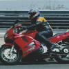
US Military Motorcycle Indian 741B (35003) 1:35 Thunder Model via PocketBond Ltd Indian Motorcycles were one of the two main motorcycle companies in the US at the time of WWII, and together with Harley Davidson supplied the Allies with the majority of their motorcycles. The 741 was a 500cc side-valve V-twin variant of their Thirty-Fifty Scout that was used predominantly by British and Commonwealth forces, as it differed from the Harley in having a foot-operated clutch that was difficult for established riders to adapt to. They were also needed to make up after a shortfall that was inevitable when the Triumph factory was bombed out during the bombing of Coventry. It was probably due to this favouritism on the US military's part that extended to cancelling contracts completely toward the end of the war, coupled with the company's lack of attention to the home market during the war that began their eventual demise, with the 741 leaving service at the end of the war and the company began a long spiral round the drain. The Kit This is a doubled-up reboxing of Thunder Model's 2017 kit, which now has two of everything, rather than just one bike in the box. It arrives in a top-hinging box with captive lid, and inside are four sprues of light grey styrene, two sheets of Photo-Etch (PE) still attached to their outer runner, a small ziplok back containing two decal sheets and a length of wire. The instruction booklet is printed in black and white, while the separate markings guide is printed on glossy paper in full colour, with profiles done by the almost ubiquitous AMMO artists. The instructions are a little confusing to my eyes, as they are printed landscape inside a portrait cover, and the orientation makes it feel wrongo to be flicking them that way. That may just be me though, so don't let it worry you. Construction begins with the wheels, which have three-part styrene tyres and rims that are layered together with two layers of PE spokes and a central spacer/drum brake to give a realistic representation of spoked wheels, although you'll need to drill out the centres and remember not to glue them, and pre-dish the PE spokes as per the instructions. The two cylinder heads are then fixed to the engine block, which is moulded into the main chassis tubes, and then has the casing, fuel tank, leg guards and handlebars added in short order. The front wheel is mated to the forks, and the single spring that gives up to 50mm of travel on the real thing attaches to the bottom of the head tube, with two more attachments lower down for strength. The rear wheel is put in place after the chain-stays are added along with the chain, and the mudguard fixes to two points on the frame, which leaves the model looking rather bike-like, although with nowhere comfy to sit yet. The exhaust, foot plates and forward mudguard stays are installed along with the chain-guard, brake linkage, kick-stand, rear lights and load rack, which has a pair of pannier bags added later, and finally the seat, perched on two springs to give the rider's bum some light relief. The final parts are instruments and filler cap on the fuel tank, with PE alternatives for some parts, and decals for the instruments. If you're going for detail, the instructions also show you where to route a length of 0.2mm wire for the brake and speedo linkage, however the included wire is 0.4mm, but I doubt many people will mind or notice. Markings There are three options in the box, one of which is for a military bike, the other two being for civilian versions, which were seen on the roads after the war. The decal sheet is small, and has a few stencils in white, instrument dials in white with black decals to put under them, and the Indian logo and name in orange, which under magnification is made up from yellow and brown (possibly) dots, although you'd be hard pushed to notice unless you were really looking. The civil options are rather bright, and just have the Indian logos or name on their two-tone fuel tanks. Conclusion A nice detailed little model times two that would look good in the background of a diorama, or with a figure riding it if you can find or adapt one suitable. Highly recommended. Review sample courtesy of UK Distributors for
-
German Bergepanzer Hetzer late 1:35 Thunder Model The Hetzer was a highly successful tank destroyer that was based on the Czech P38(t), which mounted a powerful 75mm gun in the glacis with limited traverse capability, obviating the need for a turret and thereby reducing its profile, but requiring the driver to slew the vehicle for gross re-targeting. The Bergepanzer variant was fitted with a smooth glacis with no gun port, and had an open top for ease of ingress by the crew, who would be in and out connecting up towing ropes etc. to any vehicle in distress, possibly whilst still under fire. Due to its designation as a "light" recovery vehicle its use was limited to an extent, and only 170 were built in total, with later models benefitting from experience in the field, and from side skirts that helped defuse the blast of shaped charges that were in use in the later part of the war. The Kit This is a variant on Thunder Model's original Bergepanzer Hetzer late, which has been released with different parts to bring a total of four boxings including this one, which is a Limited Special edition with some upgrades to detail in the shape of metal and resin parts. Thunder Model are another Chinese company, with a number of unusual kits under their belts already, and some more to be released going forwards. Their tooling style reminds me of Hasegawa, whether it's the colour of styrene they use, or the look of the parts, I'm not sure. Their boxes have captive lids, opening up to reveal seven sprues of that grey styrene, plus the extras, which you will find in a ziplok bag. Take care when opening the bag, as some of the parts are necessarily small and easily lost. There are two sheets of copper Photo-Etch (PE), a small sheet of brass PE, another nickel plated fret with painted dials, a length of brass chain, three lengths of braided string/rope with no fuzzy threads, a length of brass wire, two short loops of thicker gauge steel and copper wire, and two resin towing cable eyes. Almost everything you will need other than glue and paint to complete your model. The instructions are printed on an A4 booklet in portrait with greyscale isometric views, and the painting guide is printed on glossy stock in full colour. Due to the open top, quite a lot of the interior will be on display, so construction begins with the engine, which is nicely detailed, with ancillary parts also included, such as fuel tanks, radiator and air ducting parts. A number of tiny rivets are added around the inside of the hull by the final drive housing, and the leaf-spring suspension units with their large wheels are added all around before the link-and-length track is built up around the road wheels and drive sprocket. The rear bulkhead is added to the hull along with the towing cables, lifting eyes and towing hooks, while the transmission box is constructed over a number of steps before it is dropped into the front of the hull, and the driver's position with PE pedals and controls are glued into the left side. Behind and to his right a power take-off runs the internal winch that passes out through the rear armour, and behind that the bulkhead is fitted to separate the engine bay from the crew compartment. The upper hull is open at the top and has a separate engine deck, which is constructed by adding an inverted T-shape with PE grilled to the centre, and fitting the two access panels at the top left and right, the winch cable exiting from the starboard side. Various PE brackets and a length of replacement track are used, and the special edition rear fenders are built up from the included PE, which can be deformed to show use in a more realistic way, as well as having more scale thickness. The Pioneer tools and the bergepanzer specific tools are festooned over the slab sides, and the crane can either be shown collapsed for transport in the port side, or with the addition of its cabling and hook, it can be shown erected on the top of the hull. A choice of PE or styrene side skirts are also fitted to the hull and fender edges, which can also be dented, twisted or plain-old ripped free depending on how good your imaginary driver was at his job. A shallow stowage bin is fitted into the crew compartment aperture, which can be fitted with a choice of pulley assemblies, and the final act involves building up the chunky entrenching blade that fits to the rear of the vehicle and hinges vertically for travel. Small PE lifting eyes are added to the rear of the blade, and an addendum is included on a slip of paper in the box for the support arms, so staple it into the booklet before you start to remind you. Markings There are two markings options in the box, but as neither have any stencils applied, there are no decals, just instructions on how to paint your Hetzer. From the box you can build one of the following: Germany, March 1945 - Dotted ambush pattern in red brown and green over a dark yellow base. Rhineland, 1945 - Wavy-edged hard demarcation pattern in red brown and green over a dark yellow base. There are tools out there to help with these schemes, such as masks for the dotted pattern, and the Clever Putty to achieve the hard lines of the wavy edged pattern. Conclusion It's worth picking up the limited edition boxing for the extras that it includes, which includes the engine compartment, as the cost saving is notable, and it will be interesting to work with the softer copper PE for the first time (for this modeller at least). Highly recommended. Review sample courtesy of UK Distributors for