Terry1954 Posted January 31, 2023 Share Posted January 31, 2023 58 minutes ago, Fritag said: although I think you mean concave rather than convex. That is exactly what I meant! I could have sworn I'd put it the other way round, but there, you seem to have it and I reckon that's looking much better now. T. 2 Link to comment Share on other sites More sharing options...
hendie Posted January 31, 2023 Share Posted January 31, 2023 Almost there but I think you need a larger fillet on the top "corners". Okay, I know it doesn't have corners, but I know what I mean And maybe less of a curve on top? 1 Link to comment Share on other sites More sharing options...
marvinneko Posted February 1, 2023 Share Posted February 1, 2023 Very cool project and amazing to watch you work with the 3d stuff. Great to see the pix where you show your work in front of the photos. I just recently learned about target towers and drogues. Now you've got me curious what the target tower looked like for the ww2 bombing and gunnery school I'm digging into. 1 Link to comment Share on other sites More sharing options...
Serkan Sen Posted February 1, 2023 Share Posted February 1, 2023 On 1/30/2023 at 8:08 PM, Fritag said: Printed neatly enough with no thought to the best orientation beyond horizontal = quickest and with only short (2mm) supports and a 1mm raft. Do you get printed exactly what you design as support and base heights? I could not managed yet getting them in the same heights as defined in cad model. Always first 2.0-2.5mm has such issue and some portion of support height disappear/sink in base thickness (due to thicker thickness than defined) Serkan Link to comment Share on other sites More sharing options...
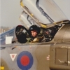
Fritag Posted February 1, 2023 Author Share Posted February 1, 2023 (edited) 22 hours ago, AndyL said: That's looking superb - makes me want to dig out the Defiant kit I donated the turret parts from and cobble together the Defiant two seat trainer. This was first proposed in 1940 to cut the wastage of Hurricanes and Spitfires at the Operational Training Unit level, but it was dropped as being 'too complex' to undertake. They tried again in 1942, with the same outcome. Did that proposal originate with Boulton Paul; maybe trying to find a use for the Defiant to keep it in production? Or was it put to Boulton Paul as a requirement that needed an aircraft? 22 hours ago, AndyL said: When the first TT Defiant was converted, they were concerns for the drogue operator as in the prototype it was deemed way too hot for them ( seating was close to the radiator ) and the possibility of the operator falling through the open floor! Did they do anything about the heat from the radiator? or just decided the operator could put up with it? 2 hours ago, Serkan Sen said: Do you get printed exactly what you design as support and base heights? Empirically I say no. I didn't measure the supports on the last print but I'm confident that they weren't as high as 2mm on top of the raft as I specified. I've taken on board your previous observations about the first few mm of the print being unreliable but I've not been systematic about trying to identify what and where the issue is. 12 hours ago, hendie said: Almost there but I think you need a larger fillet on the top "corners". Okay, I know it doesn't have corners, but I know what I mean And maybe less of a curve on top? Can't do a larger fillet on the top 'corners' (shoulders?); 1.5mm is that largest the algorithm will allow/compute. I'd have to make the cross section profile rounder at the 'shoulders' to soften the curve in the loft more. Trouble is, one of the minority of things that the 2 sets of plans I have agree on is the curve at the shoulders and so I'm reluctant to just eyeball a change. As to the curve on top. Of the 2 sets of plans - you've guessed it - one sets shows a more curved top cross section profile than the other. I've now adopted the less curved profile in the sketch as I think your right that it appears to accord better with the photographs; albeit that there's subjectivity of observation when it comes to photographs again. But both plans can't be correct.... But both plans could of course be incorrect... I'm not absolutely convinced yet that the bottom portion is concave rather than convex but the various photographs are difficult to interpret. The shadow in this IWM photo appears to suggest that there's a diagonal contour marking the transition from fuselage below the canopy and fuselage below the operators cockpit; but of so that diagonal aint' apparent on the photos I posted above and I'm not inclined to attach too much evidential weight to just one photo. Edited February 1, 2023 by Fritag 13 1 Link to comment Share on other sites More sharing options...
CedB Posted February 4, 2023 Share Posted February 4, 2023 Honestly, these people that don't put links into their threads for new builds… what do you think I am, an explorer or something? If you did put a link in I apologise profusely and claim a senior moment. Again. Lovely work here Steve, as usual. I look forward to seeing it in the flesh at Jim's later in the year when I hope I too have something to deliver. 8 Link to comment Share on other sites More sharing options...
bigbadbadge Posted February 6, 2023 Share Posted February 6, 2023 Some lovely photos here and some great 3D work, a dark art to me, intriguing none the less though. Great work Chris 1 Link to comment Share on other sites More sharing options...
Ex-FAAWAFU Posted February 9, 2023 Share Posted February 9, 2023 The sweetheart child of a Battle/Fulmar tail, Skua mid-section (sit-up-and-beg cockpit) and Trop Hurricane nose (engine). With a windmill bolted on the side and a Bond villain system for disposing of the winch operator through the “open floor” (which blunt Naval types would probably call a “hole”). Could this aircraft possibly be more British? One wonders what the USAAF types who flew it thought! [Lovely Fusion-ery, Steve, obvs] 9 Link to comment Share on other sites More sharing options...
Hamden Posted February 9, 2023 Share Posted February 9, 2023 @Fritag Not Defiant related but found this the other day https://www.facebook.com/aviationmt/photos/a.820373198324675/1891682681193716/ Don't know if you were serving when this was taken but hope it might bring back good memories! Stay safe Roger 1 Link to comment Share on other sites More sharing options...
Brandy Posted February 9, 2023 Share Posted February 9, 2023 That looks much better, but I'm still not sure that the fuselage around the lower part of the operator's cockpit, at the same level as the bottom part of the canopy, widens out at all. It looks straight to me, but your the one with the drawings.... Ian Link to comment Share on other sites More sharing options...
Fritag Posted February 16, 2023 Author Share Posted February 16, 2023 (edited) Morning all, It's been a couple of weeks since I've had much time for anything modelling and BM related - what with spending a pleasant week in Devon and the demands of real-world-work. Although I should perhaps admit that the pressure of the real-word-work is not entirely unrelated to having a week off in Devon and in anticipation of a week skiing at Tignes in 10 day's time. Just saying... So where was I? On 2/9/2023 at 11:55 AM, Hamden said: Don't know if you were serving when this was taken but hope it might bring back good memories! Thanks Roger. I wasn't serving then, still doing my O levels . But it's nice photo and does remind me of taking a Jag away to warmer climes and then noticing how much longer the poor old girl took to get airborne in very hot weather... On 2/9/2023 at 5:09 PM, Brandy said: That looks much better, but I'm still not sure that the fuselage around the lower part of the operator's cockpit, at the same level as the bottom part of the canopy, widens out at all. It looks straight to me, but your the one with the drawings.... I'm pretty sure it widens out around the operators cockpit, just at the level of the bottom of the operators canopy, Ian. These two photos (in my view) highlight the slight curve at the side of the operators cockpit at that level, and agree with the plans in the Franks book 'The Boulton Paul Defiant, A Technical Guide' I'm using. That said, looking again at the photographs has persuaded me that I've overdone the curve slightly and I've slimmed it down a little. I've also concluded that the front fairing for the operators cockpit flairs out from the fuselage behind the pilots cockpit in a convex and not a concave curve. I'm not sure there's a definitive photograph but zooming in on the top photograph above is one of those that strongly suggests convex. It's also the way that Classic Airframes and MPM moulded it on their kits. So convex it is. Anyway. Latest and last (hopefully) model of the basic outline of the rear decking: I did this just before we went to Devon but didn't have an opportunity to post it. I've printed it now; more on which below. Since we've been back I've had time to turn my attention to the oil cooler fairing below the nose. As well as having a longer nose to incorporate the Merlin XX engine the TT Mk I also had a larger oil cooler and so the intake fairing (which I think is also the carburettor air intake) below the nose is larger than on the Mk I. Here it is in all its multi-curvedness. This stumped me for a while at my level of Fusion competence. But the application of brute force and ignorance brought progress of a sort. I tried to break the structure down into logical sections capable of being 'lofted' from profiles and with guide rails. Rear: Front: Front Upper: Combined and a fillet applied to replicate the curves above the intake. Compared well in profile with my plans: And combined well with the nose: Then I hit a snag. I needed a nice large fillet all around the join between the oil cooler and the nose to create the smooth curved look of the original. But Fusion would not play ball and the algorithm simply refused to calculate a fillet. I simplified the bodies as much as possible to reduce the number of different sections in the route of the fillet and made sure there were no small sections of line or faces to impede the operation. But it wouldn't have it. I tried producing the shapes as solids and surfaces and whilst the errors were different the end result was still a failure to fillet. There may be a solution in the forms environment or by using 3d sketching and/or a sweep that is beyond my ken at present - and any suggestions from the hive would be welcome. In the meantime I've come up with a sort of rather cumbersome and inelegant bodge as a working solution. I created a serious of planes and sketches at intervals and angles at the interface of the oil cooler and nose as here: And then lofted a 'fillet' in two sections. Rear (port side): And front (port side): Mirrored and combined: And when combined there's now a sort of collar around the Oil Cooler: With an end result of a 'fillet' between the Oil Cooler and the nose: I've called it an inelegant bodge because the edges of the lofts don't (can't be made to) achieve a perfect intersection at every point around the body of the Oil Cooler or with the surface of the nose. You can see this on the screen prints where there is some bleed through/roughness at the edges of the 'fillet'. So this is an inelegant piece of CAD (for which I apologise to those more talented than me; but the real question is whether the bodge is good enough in practice. Which brings me to last night's print run: I do believe we have the beginnings of a Defiant TT Mk I: The somewhat slimmed down widening around the operators cockpit that I referred to earlier. The contours of the operators cockpit front fairing are as good as I can make them I think. I doubt it's definitive but the best I can do on the photos, diagrams and plans I have. The Oil Cooler fillet 'bodge' printed pretty well. Still don't like it as a solution but it may be good enough. The contours of the new nose compare pretty well with photographs. Overall I'm pretty pleased with how it's going. My first attempt at a major structural/shape changes using Fusion/printing and it's challenging but enjoyable. Edited February 16, 2023 by Fritag Typo's 30 1 Link to comment Share on other sites More sharing options...
Brandy Posted February 16, 2023 Share Posted February 16, 2023 I'd say you've very inelegantly nailed it! Looks fine to me, and after seeing those first two pics I agree that there is a slight widening for the operator's cockpit. Great job! Ian 2 Link to comment Share on other sites More sharing options...
AndyL Posted February 16, 2023 Share Posted February 16, 2023 @Fritag - in answer to your question ref the winch operator, IIRC the bulkhead was insulated to reduce the heat in the compartment. I've had a rummage and found a few images that may be of use. 8 1 Link to comment Share on other sites More sharing options...
Terry1954 Posted February 16, 2023 Share Posted February 16, 2023 That's all looking pretty good Steve, and nailed it you seem to have done! Did your Devon trip get to include the FAA museum? I've heard recently from a mate, that a number of the decent Cold War types have been removed into storage, so the experience was not what it was. T. 1 Link to comment Share on other sites More sharing options...
Fritag Posted February 16, 2023 Author Share Posted February 16, 2023 3 hours ago, AndyL said: in answer to your question ref the winch operator, IIRC the bulkhead was insulated to reduce the heat in the compartment. I've had a rummage and found a few images that may be of use. Thanks Andy, and useful photo's too. That one of the inside of the rear fuselage is excellent. The few photos of the USAAF pair that I've seen show them without the winch windmill, which I think means that they had an internal motorised winch - although I've no plans to have the winch fairing removed to show it. They also don't have the flag container underneath the rear of the fuselage - which is good as it's one less thing to have to make. I'm not sure what if anything that says about the sort of target towing they were doing. I've also noticed that the port side of the operators cockpit hinges down to form a door. I've not seen anything to suggest that the starboard side also hinges open but I suppose it might. Anyway, if I can get enough references of the operators cockpit (there are a few photos and drawings in the Franks book) I may well model the port door open. 2 hours ago, Terry1954 said: Did your Devon trip get to include the FAA museum? I've heard recently from a mate, that a number of the decent Cold War types have been removed into storage, so the experience was not what it was Yes it did Terry, and bl**dy good it was too. I didn't know that any Cold War types had been removed so I didn't miss them. There's lots to like and admire in the museum, but the highlight for me was the Sea King ZA298 - what an operational history. I also enjoyed peering over the Lynx XZ720, which Crisp, @Ex-FAAWAFU has in his log book. And I so enjoyed the Corsair KD431 with it's conserved paintwork that I bought the book covering the research and conservation work done on it. 6 Link to comment Share on other sites More sharing options...
Terry1954 Posted February 16, 2023 Share Posted February 16, 2023 20 minutes ago, Fritag said: I also enjoyed peering over the Lynx XZ720, which Crisp, @Ex-FAAWAFU has in his log book. Yes I believe it was this one, XZ720 ............ I took that (along with about 700 other pics) on my last visit, a while back now. I do also recall being there after Telford 2019 with @CedB, @Navy Bird, @Cookenbacher and @Procopius and I am certain Ced took a group selfie in front of that Lynx ..........? I want to go back there soon to see for myself how it has changed without some of the ley Cold War jets. I guess there is always plenty of other stuff to see. Thread drift over with suitable apologies! Terry 8 Link to comment Share on other sites More sharing options...
giemme Posted February 16, 2023 Share Posted February 16, 2023 5 hours ago, Fritag said: Overall I'm pretty pleased with how it's going. Looks like it's almost done, actually. Paint soon? Ciao 8 Link to comment Share on other sites More sharing options...
perdu Posted February 16, 2023 Share Posted February 16, 2023 1 hour ago, giemme said: Looks like it's almost done, actually. Paint soon? Oh I dont know Giorgio, I'd say more likely another fortnight's work 6 Link to comment Share on other sites More sharing options...
bigbadbadge Posted February 16, 2023 Share Posted February 16, 2023 Looks great to me although I know nothing of the type, nor 3D printing, it's like magic to me!!! Cracking work Chris 2 Link to comment Share on other sites More sharing options...
PeteH1969 Posted February 16, 2023 Share Posted February 16, 2023 9 hours ago, Fritag said: Morning all, It's been a couple of weeks since I've had much time for anything modelling and BM related - what with spending a pleasant week in Devon and the demands of real-world-work. Although I should perhaps admit that the pressure of the real-word-work is not entirely unrelated to having a week off in Devon and in anticipation of a week skiing at Tignes in 10 day's time. Just saying... So where was I? Thanks Roger. I wasn't serving then, still doing my O levels . But it's nice photo and does remind me of taking a Jag away to warmer climes and then noticing how much longer the poor old girl took to get airborne in very hot weather... I'm pretty sure it widens out around the operators cockpit, just at the level of the bottom of the operators canopy, Ian. These two photos (in my view) highlight the slight curve at the side of the operators cockpit at that level, and agree with the plans in the Franks book 'The Boulton Paul Defiant, A Technical Guide' I'm using. That said, looking again at the photographs has persuaded me that I've overdone the curve slightly and I've slimmed it down a little. I've also concluded that the front fairing for the operators cockpit flairs out from the fuselage behind the pilots cockpit in a convex and not a concave curve. I'm not sure there's a definitive photograph but zooming in on the top photograph above is one of those that strongly suggests convex. It's also the way that Classic Airframes and MPM moulded it on their kits. So convex it is. Anyway. Latest and last (hopefully) model of the basic outline of the rear decking: I did this just before we went to Devon but didn't have an opportunity to post it. I've printed it now; more on which below. Since we've been back I've had time to turn my attention to the oil cooler fairing below the nose. As well as having a longer nose to incorporate the Merlin XX engine the TT Mk I also had a larger oil cooler and so the intake fairing (which I think is also the carburettor air intake) below the nose is larger than on the Mk I. Here it is in all its multi-curvedness. This stumped me for a while at my level of Fusion competence. But the application of brute force and ignorance brought progress of a sort. I tried to break the structure down into logical sections capable of being 'lofted' from profiles and with guide rails. Rear: Front: Front Upper: Combined and a fillet applied to replicate the curves above the intake. Compared well in profile with my plans: And combined well with the nose: Then I hit a snag. I needed a nice large fillet all around the join between the oil cooler and the nose to create the smooth curved look of the original. But Fusion would not play ball and the algorithm simply refused to calculate a fillet. I simplified the bodies as much as possible to reduce the number of different sections in the route of the fillet and made sure there were no small sections of line or faces to impede the operation. But it wouldn't have it. I tried producing the shapes as solids and surfaces and whilst the errors were different the end result was still a failure to fillet. There may be a solution in the forms environment or by using 3d sketching and/or a sweep that is beyond my ken at present - and any suggestions from the hive would be welcome. In the meantime I've come up with a sort of rather cumbersome and inelegant bodge as a working solution. I created a serious of planes and sketches at intervals and angles at the interface of the oil cooler and nose as here: And then lofted a 'fillet' in two sections. Rear (port side): And front (port side): Mirrored and combined: And when combined there's now a sort of collar around the Oil Cooler: With an end result of a 'fillet' between the Oil Cooler and the nose: I've called it an inelegant bodge because the edges of the lofts don't (can't be made to) achieve a perfect intersection at every point around the body of the Oil Cooler or with the surface of the nose. You can see this on the screen prints where there is some bleed through/roughness at the edges of the 'fillet'. So this is an inelegant piece of CAD (for which I apologise to those more talented than me; but the real question is whether the bodge is good enough in practice. Which brings me to last night's print run: I do believe we have the beginnings of a Defiant TT Mk I: The somewhat slimmed down widening around the operators cockpit that I referred to earlier. The contours of the operators cockpit front fairing are as good as I can make them I think. I doubt it's definitive but the best I can do on the photos, diagrams and plans I have. The Oil Cooler fillet 'bodge' printed pretty well. Still don't like it as a solution but it may be good enough. The contours of the new nose compare pretty well with photographs. Overall I'm pretty pleased with how it's going. My first attempt at a major structural/shape changes using Fusion/printing and it's challenging but enjoyable. MMM very nice CAD work and nice printing of the parts. Pete 1 Link to comment Share on other sites More sharing options...
hendie Posted February 16, 2023 Share Posted February 16, 2023 10 hours ago, Fritag said: But Fusion would not play ball and the algorithm simply refused to calculate a fillet. I've had that in SolidWorks a few times. Sometimes it's my fault, but sometimes not. There are occasions where I haven't merged the bodies so SW sees them as two separate objects and will not create a feature to span them. Other times I've had to turn off select tangential edges as SW tries to second guess me. On those occasions I can generally create a fillet part way along the seam, and a second fillet command will let me complete the job - don't ask why. Inelegant as you may think your solution is, sometimes it's just easier to brute force it and carry on. Judging by the photos I don't think the printer knows it's inelegant either so I think you're safe. 4 Link to comment Share on other sites More sharing options...
Ex-FAAWAFU Posted February 17, 2023 Share Posted February 17, 2023 The FAA Museum has significantly more aircraft than it can display at any one time - hence the reserve collection - and every so often it rotates exhibits in and out of reserve. Last year they re-jigged the “Carrier” area (which had remained unchanged in well over a decade), and yes, some of the Cold War jets went into reserve or were moved elsewhere, and some (e.g. the Wyvern) came out of reserve. The counter-argument is that the Carrier area is now a lot less cluttered, so you can see more of those airframes that are on display… so it’s swings and roundabouts. Visitors used to say there were too many aircraft in that area, so you couldn’t really see them. Plus the Reserve Collection is open two or three times a year, so you can always get to see their gems if you really want to. Neither of their two Fireflys (Mk.1 or 4) is in the main museum at present, for example. That Corsair restoration book is fascinating, Steve. Aerial archeology. They are applying the same level of precision & record-keeping to the long-running Barracuda rebuild. If anyone’s interested (& why wouldn’t you be?) search for Fairey Barracuda DP872 Rebuild on Facebook 4 1 Link to comment Share on other sites More sharing options...
RichieW Posted February 17, 2023 Share Posted February 17, 2023 I may have spammed you up with plenty of likes. I am constantly amazed by the precision that can be achieved by 3d printing. I reckon if Harry Woodman were still with us he would have embraced the technology. Apart from the amazing skills on show I am utterly stunned to learn that the USAAF had a couple of Defiants. Who would have thought such an aircraft would sit alongside the Sopwith Camel, Spitfire, Mosquito and Harrier as British types operated by the USAAF? 😂 Richie Link to comment Share on other sites More sharing options...
The Spadgent Posted February 20, 2023 Share Posted February 20, 2023 Overall I’d say she looks pretty much spot on. I really wouldn’t beat yourself up about how you got to where you got to, in my eyes it’s all about the finished thing and you’ve nailed it. Again!!! Bravo that man. oh and ⛷️🚠🎿. Again!!! 🤣 Johnny 3 Link to comment Share on other sites More sharing options...
Biggles87 Posted February 20, 2023 Share Posted February 20, 2023 Wot ‘e said. John 2 Link to comment Share on other sites More sharing options...

Recommended Posts
Create an account or sign in to comment
You need to be a member in order to leave a comment
Create an account
Sign up for a new account in our community. It's easy!
Register a new accountSign in
Already have an account? Sign in here.
Sign In Now