Zephyr91 Posted January 26, 2023 Share Posted January 26, 2023 50 minutes ago, Fritag said: Now I’ve gotta say that statement is impressive. Back in the late 80’s when I was doing the Jaguar QWI course, I did a presentation on the EAP, the technology demonstrator for the Typhoon. Makes me feel old… Sounds possibly better than it should, but I was part of the aerodynamics team (albeit junior)........ Even more so with EAP. I was involved with a significant amount of the early flight test monitoring from an aeroelastics and dynamic loading point of view. Great times - well I thought so 🙂 Although it seems like "yesterday", I was somewhat chastened when I visited Cosford last year. What was in the 1980's cutting edge stuff is now in the museum - at least now they've stopped the Loughborough students having sole pleasure of and access to EAP! How did your presentation go...........no, no I shouldn't do "thread drift". cheers Rob 3 2 Link to comment Share on other sites More sharing options...
Fritag Posted January 28, 2023 Author Share Posted January 28, 2023 (edited) Thread drift?. No such thing in one of my builds Rob. You should see where some of the notorious types on BM have dragged em. To be fair, probably when bored with the large down-time between progress with a build On 1/26/2023 at 9:43 PM, Zephyr91 said: What was in the 1980's cutting edge stuff is now in the museum - at least now they've stopped the Loughborough students having sole pleasure of and access to EAP! How did your presentation go Well, all I can really remember is it was bl**min hard getting any information about it out of anyone. Must have gone all right as I passed the QWI course So. Test print of the TT rear insert fuselage insert. Not displeased. I know the fairing at the front of the insert needs some more work in Fusion. It’s a complicated transition from a squarish cross section at the front (basically the shape of the pilots cockpit canopy) to the rounded cross section at the rear (the shape of the TT operators canopy) with the added complexity of flaring out to a rounded triangular shape at the lower extremity to meet the fuselage. This is the sketching for the front fuselage fairing as it stands: I’ve caught the basic shape of the fairing at the front, but I need to iron out the creases at the side as the 1:1 is a constantly changing curved surface. I did think of using the forms environment and sculpting it; but actually it’s getting there using standard lofts from two sketches with a series of guide rails. I hopefully just need to play with the guide rails or add one or two more planes and sketch a few more guide rails and let the algorithm in the loft smooth it out…. There’s also a rather irritating c. 1 or 2 degree difference in the angle of the rear fuselage top line of the insert from the residual fuselage left on the kit. Can’t decide at the mo’ whether to adjust the angle of the insert (it’ll mean amending several intersecting sketches), remove the remainder of the upper fuselage from the kit and print it all (an option I considered at the outset), or ignore it on the basis that it’s a small discrepancy that will probably disappear during the ‘non-virtual’ fitting and making good stages of the build. Edited January 28, 2023 by Fritag Typo 24 Link to comment Share on other sites More sharing options...
hendie Posted January 28, 2023 Share Posted January 28, 2023 6 hours ago, Fritag said: it’ll mean amending several intersecting sketches... or ignore it on the basis that it’s a small discrepancy I think I know the answer to this one 1 11 Link to comment Share on other sites More sharing options...
giemme Posted January 28, 2023 Share Posted January 28, 2023 38 minutes ago, hendie said: I think I know the answer to this one Me too... Ciao 1 5 Link to comment Share on other sites More sharing options...
Phoenix44 Posted January 28, 2023 Share Posted January 28, 2023 (edited) Lovely work and the 3D stuff us fascinating. Apparently Kingkit have 3 of the CA version if you want to check your profiles: https://www.kingkit.co.uk/product/classic-airframes-aircraft-1-48-482-bp-defiant-tt-mki-&-tt-mkiii Edited January 28, 2023 by Phoenix44 1 Link to comment Share on other sites More sharing options...
PeteH1969 Posted January 28, 2023 Share Posted January 28, 2023 PM Sent to you. Pete 1 Link to comment Share on other sites More sharing options...
Fritag Posted January 29, 2023 Author Share Posted January 29, 2023 9 hours ago, PeteH1969 said: PM Sent to you. Noted, actioned, thanks Pete. 14 hours ago, hendie said: I think I know the answer to this one 13 hours ago, giemme said: Me too... Oh yeah. Ok - amending the several intersecting sketches….. 4 1 Link to comment Share on other sites More sharing options...
perdu Posted January 29, 2023 Share Posted January 29, 2023 36 minutes ago, Fritag said: 10 hours ago, PeteH1969 said: PM Sent to you. Noted, actioned, thanks Pete. 14 hours ago, hendie said: I think I know the answer to this one 14 hours ago, giemme said: Me too... Oh yeah. Ok - amending the several intersecting sketches….. I wonder what Steve will do children? I wonder what hendie would do too? Exciting times. I do know what SIHRSC would do on the basic kit, I remember what Alan Hall had me do with the old Airfix version with balsa wood and dope loaded with talc. This is lots more fun. 2 4 Link to comment Share on other sites More sharing options...
Serkan Sen Posted January 29, 2023 Share Posted January 29, 2023 21 hours ago, Fritag said: Can’t decide at the mo’ whether to adjust the angle of the insert (it’ll mean amending several intersecting sketches), remove the remainder of the upper fuselage from the kit and print it all (an option I considered at the outset), or ignore it on the basis that it’s a small discrepancy that will probably disappear during the ‘non-virtual’ fitting and making good stages of the build. Looks very good Steve. I would only increase the section height at the rear end (where 1.5cm line stands) by 0.5mm to fix this issue. But I am sure you will try the challenging way 🙂 Serkan 1 Link to comment Share on other sites More sharing options...
The Spadgent Posted January 29, 2023 Share Posted January 29, 2023 Yes I’d do what @Serkan Sen said. Obvs I don’t lift I just model, so in my case I’d pull the verts up at the rear a little to solve the issue. It’s a darn good fit you have already. Lovely work chap. Johnny 1 Link to comment Share on other sites More sharing options...
Terry1954 Posted January 29, 2023 Share Posted January 29, 2023 2 hours ago, perdu said: I do know what SIHRSC would do on the basic kit, C'mon Bill, do we ever really expect Steve to be doing stuff with a SIHRSC? Beers all round on me if we ever see that day 🍺 T. 3 Link to comment Share on other sites More sharing options...
Fritag Posted January 29, 2023 Author Share Posted January 29, 2023 3 hours ago, Serkan Sen said: I would only increase the section height at the rear end (where 1.5cm line stands) by 0.5mm to fix this issue. But I am sure you will try the challenging way 🙂 That’s what I’ve now done Serkan, but also extended the new resin deck back to near the base of the vertical fin so there’s no possibility of there being a visible change of angle half way along the fuselage. There are knock on changes to some of the more forward cross section profiles but not particularly challenging 2 hours ago, The Spadgent said: Yes I’d do what @Serkan Sen said. Obvs I don’t lift I just model, so in my case I’d pull the verts up at the rear a little to solve the issue. It’s a darn good fit you have already. Lovely work chap. I may still try modelling the front section in front of the operators canopy, rather than doing it with lofts. It’s a pesky shape. 2 hours ago, Terry1954 said: C'mon Bill, do we ever really expect Steve to be doing stuff with a SIHRSC? Beers all round on me if we ever see that day 🍺 So Terry, if Bill lends me a SIHRSC and I make a few swipes with it just before Telford next year…… 4 6 Link to comment Share on other sites More sharing options...
perdu Posted January 29, 2023 Share Posted January 29, 2023 Home or to chambers Steve? Hur hur. 6 Link to comment Share on other sites More sharing options...
perdu Posted January 29, 2023 Share Posted January 29, 2023 3 hours ago, Fritag said: just before Telford next year…… So we won't be seeing it this year then? (Colour me optimistic) 4 Link to comment Share on other sites More sharing options...
Terry1954 Posted January 29, 2023 Share Posted January 29, 2023 4 hours ago, Fritag said: So Terry, if Bill lends me a SIHRSC and I make a few swipes with it just before Telford next year…… Interesting take on the definition of "doing stuff with" a SIHRC. Lack of clarity on my part obvs (I've lost many wagers that way), but would that really be classed as using said tool in earnest, and would cajoling Bill in this way make an admissible case? I guess I should be careful with all this................... dealing with a lawyer can be fraught with wordy complexities 🙄 I never learn do I. 43 minutes ago, perdu said: So we won't be seeing it this year then? Nice try Bill! Terry 4 Link to comment Share on other sites More sharing options...
perdu Posted January 29, 2023 Share Posted January 29, 2023 What one can, one tries Terry mate. 5 Link to comment Share on other sites More sharing options...
Fritag Posted January 30, 2023 Author Share Posted January 30, 2023 (edited) Evening peeps. So, the design was revisited. The fuselage insert taken rearwards to just in front of the fin and the design (believe it or not) simplified with fewer cross sections and the shape maintained in the loft by the use of a few strategic guide rails. Lofts ok. This is again just a test piece with simple solid lofts followed by use of the shell and extrude (cut) commands. Printed neatly enough with no thought to the best orientation beyond horizontal = quickest and with only short (2mm) supports and a 1mm raft. And I'm pleased to report that it fits neatly enough too (nb. the bottom edge of the print is a little rough where I was somewhat hasty/careless trimming the supports away) : The little bulges either side of the kit fuselage are where it flares out to meet the Mk I turret. They'll sand off easily enough later on. And with the pilot's canopy in the slid-back open position, the rather bizarre shape of the TT fuselage is seen. On reflection I don't know why I originally planned to have the join halfway along the fuselage when to do so always risked any slight change in contour being more visible. I think I still have a little more work to do on the contours of the fairing at the front of the insert: But it's close. Just a bit more rounded, I think. And tbh I could probably fix it with a few passes of a 1000 grit Tamiya sanding sponge. But that would feel like cheating a bit So, now need to sort out the contours of the very front of the Merlin XX nose and the rear fuselage fairing and I can move on. Edited January 30, 2023 by Fritag 24 Link to comment Share on other sites More sharing options...
Terry1954 Posted January 30, 2023 Share Posted January 30, 2023 Lovely work there Steve, and I agree it's looking close to the profile in that picture. 23 minutes ago, Fritag said: And tbh I could probably fix it with a few passes of a 1000 grit Tamiya sanding sponge. This sort of talk makes me nervous. Are you gently letting me down towards your eventual use of a SIHRC by any chance? 😰 T. 1 4 Link to comment Share on other sites More sharing options...
hendie Posted January 30, 2023 Share Posted January 30, 2023 (edited) Nice lofting there Steve. 2 hours ago, Fritag said: Just a bit more rounded, I think. Are you talking about the lateral to longitudinal fillet? Or the fillet between the curved spine and where it goes vertical with that hump thingy? Variable fillets may be your friend there (either way) Edited January 30, 2023 by hendie Auto correct kept trying to ruin my day 1 Link to comment Share on other sites More sharing options...
AndyL Posted January 31, 2023 Share Posted January 31, 2023 That's looking superb - makes me want to dig out the Defiant kit I donated the turret parts from and cobble together the Defiant two seat trainer. This was first proposed in 1940 to cut the wastage of Hurricanes and Spitfires at the Operational Training Unit level, but it was dropped as being 'too complex' to undertake. They tried again in 1942, with the same outcome. When the first TT Defiant was converted, they were concerns for the drogue operator as in the prototype it was deemed way too hot for them ( seating was close to the radiator ) and the possibility of the operator falling through the open floor! 2 Link to comment Share on other sites More sharing options...
Brandy Posted January 31, 2023 Share Posted January 31, 2023 Nicely done on the insert Steve. It looks (to me) from the pics that it should be pinched in more right behind the lower edge of the canopy. I don't see any flare out, just a smooth transition from open canopy to rear fuselage. Certainly below the bottom edge where the fuselage lines appear to run smoothly all the way back. Ian 1 Link to comment Share on other sites More sharing options...
giemme Posted January 31, 2023 Share Posted January 31, 2023 Well done on that insert, Steve -almost there (meaning: almost perfect!) Ciao 1 Link to comment Share on other sites More sharing options...
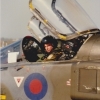
Fritag Posted January 31, 2023 Author Share Posted January 31, 2023 1 hour ago, Brandy said: Nicely done on the insert Steve. It looks (to me) from the pics that it should be pinched in more right behind the lower edge of the canopy. I don't see any flare out, just a smooth transition from open canopy to rear fuselage. Certainly below the bottom edge where the fuselage lines appear to run smoothly all the way back. I think you're onto something there Ian, although the angle of the photograph is somewhat deceiving. The fuselage has to transition between these two very different cross sections in only a little over 3mm (at 1/48). So there is no widening at all at the bottom corner, but quite a lot of widening required abeam the bottom of the canopy shaped front cross section, and then very little half way up the canopy before widening out again. Both the MPM 1/72 kit: And the CA 1/48 kit Solve the transition by having the fuselage at the bottom of the canopy shaped front cross flare out at almost at 90 degrees to the fuselage and then curve sharply backwards. And and I was influenced in my approach by them. But now I'm not so sure. Really good photographs of the area are hard to come by. the best I've found are these (cropped): Which suggest that MPM and CA exaggerate the flare and curve somewhat and I probably have done too. But it's a tricky transition to model and no mistake.... 15 Link to comment Share on other sites More sharing options...
Terry1954 Posted January 31, 2023 Share Posted January 31, 2023 52 minutes ago, Fritag said: But it's a tricky transition to model and no mistake.... Looks extremely tricky to me. FWIW I tend to agree with Ian re the "join". I'd describe the lower part of that transition as a convex curve outwards, rather than concave. I've not explained that well, but I know what I mean! T. 1 Link to comment Share on other sites More sharing options...
Fritag Posted January 31, 2023 Author Share Posted January 31, 2023 28 minutes ago, Terry1954 said: I'd describe the lower part of that transition as a convex curve outwards, rather than concave. I've not explained that well, but I know what I mean! I know what you mean too, Terry: although I think you mean concave rather than convex. And I think you may have put your finger on summat. Redrawn with a concave curve at the level of the bottom of the canopy transitioning through neutral to convex at the top plus a few fillets as suggested by Alan A few photos in the design and render mopde sandwiching a similar angle photo of the 1:1 for comparison. I think that's rather more like it meself. And if so it's a combination of Ian + Terry on the visuals + Alan on the technique... 20 Link to comment Share on other sites More sharing options...

Recommended Posts
Create an account or sign in to comment
You need to be a member in order to leave a comment
Create an account
Sign up for a new account in our community. It's easy!
Register a new accountSign in
Already have an account? Sign in here.
Sign In Now