dogsbody Posted January 31, 2023 Share Posted January 31, 2023 Photos not showing and can't open them on a new page. Chris Link to comment Share on other sites More sharing options...
Brigbeale Posted February 1, 2023 Author Share Posted February 1, 2023 13 hours ago, dogsbody said: Photos not showing and can't open them on a new page. Chris I’ve just looked at the IMGBB website. It’s down at the moment so I’ll repost the pictures using Imgur instead. Link to comment Share on other sites More sharing options...
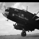
Brigbeale Posted February 1, 2023 Author Share Posted February 1, 2023 (edited) The pictures from my previous post using Imgur. Edited February 1, 2023 by Brigbeale 5 Link to comment Share on other sites More sharing options...
Brigbeale Posted February 1, 2023 Author Share Posted February 1, 2023 With the bomb aimer’s window opening adjusted widthways with the 1mm styrene card, I sandedthe contour to match the other side. This revealed the extent of the filling required to bring it up to shape. Knowing the nose turret interior is probably going to be more visible with the vac formed glazing, I decided it would need a turret floor and back to fit inside. Using 28mm Tamiya tape placed on the top of the opening, I cut a template with a sharp tip knife and cut the shape from 1mm styrene card. The same technique was used to cut the turret rear panel. It was scored on the back and the two outer edges were bent forward to emulate the shape of the turret. Once painted black and fitted in with the vac form glazing, it should turn out a whole lot better than an open back. I plan to fit the turret wall once the fuselage halves are United to allow me to add some interior detail while its fitted in place. The bomb aimer’s panel was replaced with a 1mm piece of styrene card. I broke out the airbrush to paint the cockpit cockpit green and the turret/bomb aimer areas flat black. 5 Link to comment Share on other sites More sharing options...
bigbadbadge Posted February 1, 2023 Share Posted February 1, 2023 Great progress Brian , the modifications are looking good as are the Vacform turretry. Chris 1 Link to comment Share on other sites More sharing options...
Brigbeale Posted February 2, 2023 Author Share Posted February 2, 2023 The cockpit was further painted tonight and also had a wash added to tone the newness of the paint down. While painting it I remembered that the control column had yet to be fitted. It took me a few minutes of sifting through the parts to find it. So once I found it, it took me a little while to clean it up of the flash, file and sand it more to shape. Once done, it was painted and fitted to the cockpit assembly. Some simple masking tape seat belts were added along with a chart and log book to the navigator’s table. The cockpit was fitted o the port half of the fuselage using TET. The starboard half was dry fitted and held in place with elastic bands to help align the cockpit. The bomb aimer’s floor also fixed to the port half. I’ve decided to use the original cockpit canopy as it fits well and is quite clear - so the interior can be seen quite well through it. 10 Link to comment Share on other sites More sharing options...
AdrianMF Posted February 2, 2023 Share Posted February 2, 2023 The original canopy is a lot clearer than my repop... Mind you, if you have the Falcon set, I'm wondering why you're not using the canopy too - maybe you are planning to do another FROG fix up? Regards, Adrian 1 1 Link to comment Share on other sites More sharing options...
Brigbeale Posted February 3, 2023 Author Share Posted February 3, 2023 19 hours ago, AdrianMF said: The original canopy is a lot clearer than my repop... Mind you, if you have the Falcon set, I'm wondering why you're not using the canopy too - maybe you are planning to do another FROG fix up? Regards, Adrian I’m not purposely looking for one, but you never know!! But Ok. I’ll cut the Falcon cockpit glazing out tonight and go from there. 1 Link to comment Share on other sites More sharing options...
Brigbeale Posted February 3, 2023 Author Share Posted February 3, 2023 The Falcon glazing was cut from the canopy set, trimmed and sanded up to fit. With some slight concern, the kit cockpit roof panel was cut from the fuselage as the vac form glazing has this piece built in. There’s no going back now! (Well, there is, but I’ll proceed with the vac from one). The sides of the cockpit opening also had to be trimmed to allow the vac form glazing to sit flush at the rear of the cockpit. The front will need some more sanding to get the glazing to sit fully down on the fuselage. The fuselage was then taken apart for what I hoped to be the last time to brush out the sanding dust and shavings from the cockpit area. With some pushing one way and then another, the fuselage halves were cemented together using TET. The seams weren’t flat or even, so where one side was pushed to line the two halves up, in another place, the other half had to be pushed to get that section to line up. Eventually, I got around the seam joining the two halves together, leaving the underside rear from the tail wheel location to the turret mount in-cemented. A small strip of 1mm styrene card was added to the rearmost part of the fuselage and then it was cemented in. Theres a gap underneath which needs filling, but I knew that was going to happen anyway. Thats then I spotted the main wing spar still sitting on the table. The first thought (after thinking ‘I’m not getting the fuselage apart again!’) was to cut a flat piece of styrene card to replace it, but then I figured I could cut the tabs off one side of it and file the tabs on the other side down to slide them in. (They locate inside the fuselage). With a firm push, they clicked in past the fuselage plastic without causing any damage - the remainder of the tabs now do the job they were intended for. The spar has been left loose until the wings get fitted to now fouled up the wing fitment later on. Why is it that even though you think you’ve cleaned all the dust off the clear parts, more appears when the camera comes out?? 8 Link to comment Share on other sites More sharing options...
Brigbeale Posted February 4, 2023 Author Share Posted February 4, 2023 (edited) The cockpit glazing was adjusted at the front by outlining the shape of the windscreens on the fuselage and gently shaving the plastic out to mark a recess for the glazing to sit into. It seems to have worked. The nose turret floor/back panel were cemented into position in the opening in the nose. The turret glazing was placed on top to ensure the base didn’t hinder the fit. Once it’s dry, I can add some bits an pieces to emulate the interior of the turret. A check was made on the fuselage to locate all of the divots and sink marks. They were circled with a pencil. Then it was a case of adding a good amount of thinned sprue-goo to the centre seam and the divots/sink marks. The model stand was adjusted for width and the fuselage gingerly placed on top - more or less in the Whitley’s flying attitude. So, while the fuselage is in the cabinet to dry, I decided I’d tackle the engine air intakes. I remembered that I had two spare sets of intakes from a Revell Halifax I/II/GRII as there were three options for the Rolls Royce engines. Two have more prominent inward curves to the sides and the other two are more conventional in shape although a little square at the bottom corners. So with much offering up, marking with a pencil and re-offering up to show an adjustment was needed the lower halves of the Halifax intakes were cut off. Then with the same offering up to the engine nacelle, the lower curve was cut off to suit. They’re not the same shape at the rear of the intake, but with some careful sanding, hopefully they’ll look better and require less filling to blend them in. The intakes also had to have about 1-2mm cut from the middle to allow the sides to line up with the nacelles. Ive left them sitting proud at the front for when I design and 3D print the replacement propeller hubs. Edited February 4, 2023 by Brigbeale 7 Link to comment Share on other sites More sharing options...
Brigbeale Posted February 6, 2023 Author Share Posted February 6, 2023 The past couple of evenings have been spent finessing the centre seam line on the fuselage. After the initial sanding, it was clear more filling was needed. So a second dose of sprue-goo was added and set aside to dry. After that was sanded, still a few areas needed more filling, which was evident by shiny dried sprue-goo spots surrounded by matt sanded sprue goo. I used Revell Plasto to fill these minor dips, and it seems to have done the job. The tapered gap under the rear of the fuselage, where the 1mm spacer was added, filled very well. The fuselage now feels smooth to the touch across the seam line. Today, I’ve been working on the 1-1 scale Mini - namely the faulty head gasket on SWMBO’s convertible. I’m still in the strip-down part of it at the moment as there’s quite a lot of stuff to remove or just move out of the way, and it’s the first Beamer Mini engine I’ve actually taken apart, so it’s a bit of a voyage of discovery. Tonight I made the second air intake for the other engine on the Whitley - not the Mini. initially, it ended up too wide so another section was cut out of it. This turned out to be from the side rather than the bottom, so that part was cemented back on and the cut made again the right location. The two halves were joined together and it’s now set aside to dry fully. I noticed the main wheels both had one side of the axle missing. They’d been previously built by the former owner so maybe there was an error in cutting them from the sprue or both were short-shotted. Either way, the simple solution was to drill 1.5mm holes in the side of the wheel and add some styrene rod. Once fitted, nobody will know. 5 Link to comment Share on other sites More sharing options...
Brigbeale Posted February 7, 2023 Author Share Posted February 7, 2023 I designed the radiator/air intake to fit into the engine intakes today and this evening 3D printed them. Both only took about 12 minutes as they’re only approx 11mm x 5mm tall and approx 2.5mm thick. i cemented a piece of 0.5mm styrene card into the bottom of the intake to lift the 3D printed items up slightly as the triangular intake at the bottom would have been mostly hidden where it was. The radiator assemblies were then cemented into position with the help of superglue behind to reinforce the joint while the TET sets. Then both air intakes were added to each engine nacelle. The port one on ended up a little short height wise, but the addition of some styrene strips helped to fill the gap. Both engines will need sanding to blend the intakes into the nacelles. I wondered if the original propeller hubs would fit the nacelles if I cut the lower half off, so I snipped the lower rounded section off and offered it up. Not 100% perfect, but maybe with some filler and some reshaping of the lower half?…….. I placed the wings on again using squares of 18mm tape to hold them. The wheels were placed in the yokes on the gear legs and the undercarriage assemblies were dry fitted to the wings. A quick measure with the ruler shows they’re both exactly the same height on the wing tips. The stabilisers were dry fitted and a block was placed under the tail to support it to get a feel of what the finished model would look like wheels down and parked. I also placed the nose turret and cockpit glazing on. The replacement intakes do look a lot better than the original kit ones. 8 Link to comment Share on other sites More sharing options...
AdrianMF Posted February 7, 2023 Share Posted February 7, 2023 I couldn't work out how you were going to use the intakes - they look great! Regards, Adrian 1 Link to comment Share on other sites More sharing options...
Brigbeale Posted February 8, 2023 Author Share Posted February 8, 2023 10 hours ago, AdrianMF said: I couldn't work out how you were going to use the intakes - they look great! Regards, Adrian Thanks Adrian, At the start of the conversion, I was wondering how I was going to get them to fit as well😆 1 Link to comment Share on other sites More sharing options...
Brigbeale Posted February 8, 2023 Author Share Posted February 8, 2023 The intakes were sanded to blend them into the nacelles and further round the squared corners to make them look a little more like Whitley intakes. Some other seams were also sanded to eliminate steps in the joints. Once that was done, and I’d cleared up the resulting dust, I figured I’d just go for it and fit the main wings. Both sides just needed a little notch filing into the leading edge of the mounting tabs. This allowed both wings to slide forward a tough to line them up on the leading edge. One wing is a good fit, but the other one is either too shallow top to bottom or the fuselage wing root is too tall. Either way, there’s going to be some sanding to remove the step in the wing to fuselage joint. The wings as per usual on the bombers, were held in place with Royal Mail issue rubber bands crossed over to pull the wing inwards evenly. 2 for the port and 2 for the starboard looped round the wing and fuselage. This is better than trying to stretch them over both wings and fuselage as they’ll put too much force on the wings, and they won’t sit correctly. Copious amounts of TET was used on the joints, so hopefully I won’t have a repeat of the Wellington fiasco. 5 Link to comment Share on other sites More sharing options...
Brigbeale Posted February 12, 2023 Author Share Posted February 12, 2023 There’s not really been much to write about with the Whitley. With the repairs to the convertible Mini head gasket and finding it need a replacement camshaft due to possible oil starvation - hence bad wear to the lobes, things haven’t progressed as far as I would have liked, but some progress was made. I found the wings were not the best fit where the upper and lowered surfaces met their counterparts on the fuselage - hence the steps between the wings and wing roots. I filled the gaps with sprue-goo and went round the joints on the nacelles as well. I left the sprue-goo to dry for two days, so I could sand it back. To my surprise, it still wasn’t 100% dry, but was ok to sand, but left a rough texture to the finish. The sprue goo had gone a little thick in the bottle so I added some TET to thin it a bit. So now it might be a bit too thinned out and may need some sprue chips adding to bring it back the right consistency. So after the best part of an hour and a half sanding the joints and the leading edges of the wings, they still weren’t filled as I would have liked, so I broke out the Revell Plasto filler and gave each joint a good application feathering it outwards. As the nacelle joints also had the sprue-goo added, they also received a dose of Plasto. With the Whitley placed flat on the cutting mat with two sanding sticks placed under each wing equally from the end, the stabiliser/elevator wings were added to the tail section. the 1mm spreader in the turret location made no difference to the fit at all. The port stabiliser did require a notch to allow it so slide forward to where it was supposed to sit though. Two wooden clothes pegs were used to space the tips and they were both measured and fount to be equal in height at their tips from the cutting mat. A quick look over the main wings to the tail wings confirmed they all looked level with each other, so the Whitley was placed in the cabinet with the improvised jig to allow the TET to set. The joints on the stabilisers will also need some filler, so I’ll add some on at some point tomorrow morning, so it can all be sanded back at the same time. 7 Link to comment Share on other sites More sharing options...
bigbadbadge Posted February 12, 2023 Share Posted February 12, 2023 Great progress Brian and it is looking good. The intakes turned out really well so far and look great. Good luck with the Mini. Chris 1 Link to comment Share on other sites More sharing options...
Brigbeale Posted February 14, 2023 Author Share Posted February 14, 2023 I added the filler to the stabilisers and while that was drying, tidied up some more flash on the smaller parts to be added later. When it was dry, I started to sand back the Plasto filler - which was messy to say the least. But, with it sanded back, the wing to fuselage seams are now smooth, as are the nacelles and the wing leading edges. With Adrian’s tip about the size of the rudder/fin assemblies being too small at the back of my mind prodding me saying “Print replacements!”, I decided to resize a side view from a colour call-out/decal placement showing the size of the rudder/fin in relation to the fuselage. The gap between the main wing root and the stabiliser gave me the distance which in turn, gave me the rudder/fin height. It seemed to tally with the Airfix colour call-out which showed the original fin/rudders were approx 3mm too short - which didn’t seem that much in reality, but when scaled up to full size it’s approx 8.5” short. I scanned the image into Onshape and started the sketching on top of the image and progressed from there. I need to practice more with the tools to get better/easier shaping. The rendering was sent to Cura and then in turn sent to the 3D printer. The first try looked ok until I returned later and found it had separated from the bed about half way through, but continued anyway leaving a stringy mess. Attempt 2 had a brim added around the part to increase bed adhesion. After about 1.5 hours, the print was finished - not perfect, but the size and shape was there. After a quick run over with the sanding stick and the supports were removed, it was trial fitted on the Whitley. Hmmm, not too sure about it, but t does tally up with the scaled image. Maybe it’s just the front edge being too chunky and needing further shaping prior to reprinting. At a cost of 4p per fin/rudder (excluding the electric), it’s not excessive to redesign it. While I was waiting for the 3D printing to complete the 2nd attempt, I cemented up and fitted the main undercarriage/wheel wells to the nacelles. The tail wheel was added also. I also re-drilled the antennae holes along the top of the fuselage and filled in a couple of misplaced holes. 6 Link to comment Share on other sites More sharing options...
stevehnz Posted February 15, 2023 Share Posted February 15, 2023 Coming along really well, I like what you're doing here & suspect, though I hope not, that I'll need to do likewise when I summon up the courage to attack mine. I do have some quite nice resin engine cowls which should help. Steve. 1 Link to comment Share on other sites More sharing options...
Brigbeale Posted February 15, 2023 Author Share Posted February 15, 2023 8 hours ago, stevehnz said: Coming along really well, I like what you're doing here & suspect, though I hope not, that I'll need to do likewise when I summon up the courage to attack mine. I do have some quite nice resin engine cowls which should help. Steve. Thanks Steve, I’ve modified the design fins to make the leading edge more slender, so I’ll just have to wait to see how they turn out. I did contemplate simply cutting the originals just under the trim tab, adding some 3mm square rod to bring them up to height and then shaping the trailing edge as required, but that’s a good plan to fall back on if I’m not entirely happy with the 3D printed ones. I did see a resin set of engines on eBay, but the seller wanted far too much for them and then wanted a fair price for postage on top! Hence the reworking of the plastic parts! 1 Link to comment Share on other sites More sharing options...
Brigbeale Posted February 15, 2023 Author Share Posted February 15, 2023 The first of the thinned leading edge fins has just finished printing and looks a whole lot better than yesterday’s prints. They need a little cleaning up to remove the support nibs. I also added the counter-weight to the tip - I bet I knock that off at some point🙄. 3 Link to comment Share on other sites More sharing options...
PattheCat Posted February 15, 2023 Share Posted February 15, 2023 You're putting an awful (*) lot of effort into this one. It's all coming along real well. Seeing your progress I'm now convinced you'll end up with a really great looking Whitley. Great job! (*) appropriate qualifier only when used by an awfully lazy guy like me feeling tired just looking at what you're doing 1 Link to comment Share on other sites More sharing options...
Brigbeale Posted February 15, 2023 Author Share Posted February 15, 2023 The first part of the evening session was to sand the 3D printed items smooth with a new sanding stick. The new stick made fairly light work of sanding even though the PLA is harder than the original plastic the kit is made from. I used a trick that I was taught when I was young and doing sign writing on a YTS scheme for teenagers after they left school. Usually, on item requiring restoration, the item to be copied was traced (say a number or an image). Coloured chalk was then rubbed on the back of the tracing paper which was then taped into position. The traced lines were then run over again, which, once removed, left a chalk outline of the intended item for re-creation. Another run round with a pencil made area ready for sign-writing incase the chalk outline got rubbed off. So, back to the present. I cut the rudder/fin part from the scaled colour call-out and simply scribbled with a pencil on the back where I could see the lines through the paper. This was then placed on the 3D printed rudder/fin and with a straight edge, the image lines were drawn again. This left the pencilled lines on the surface. Then it was just a case of carefully scribing the lines into the part with my Tamiya Scriber. To do the other side, I printed a reversed image and did the same again. A quick rub over with the worn sanding stick tidied up the swarf and highlighted the scribed panel lines. The two were fitted into position with white-tac so see what they looked like. I’m happy with them. I need to work out how easy it would be to mask the area for the intended paint scheme if the fins and the stabiliser rods are fitted. It may be easier to fit them after painting the fuselage and wings. 5 Link to comment Share on other sites More sharing options...
Brigbeale Posted February 17, 2023 Author Share Posted February 17, 2023 I took last night off to take care of another non modelling related issue which cropped up. Tonight, I decided I needed to sort the propeller mounts/engine fronts. I designed them in Onshape and then 3D printed them. Although they turned out quite well, they were very slightly to narrow and needed more curve to the sides, so they’re were re-designed and are currently re-printing. they only take about 25 minutes to print the two at a cost of a whole penny! I’ve made the prop shaft hole smaller as the original bushes are so badly moulded they’re practically useless as the shafts just flop around inside them. 4 Link to comment Share on other sites More sharing options...
PeteH1969 Posted February 18, 2023 Share Posted February 18, 2023 Great work. I'm surprised to see that you are using an FDM printer and pleased to see what great results you are getting from it very nice. 👍 Pete Link to comment Share on other sites More sharing options...

Recommended Posts
Create an account or sign in to comment
You need to be a member in order to leave a comment
Create an account
Sign up for a new account in our community. It's easy!
Register a new accountSign in
Already have an account? Sign in here.
Sign In Now