Brigbeale Posted November 4, 2022 Share Posted November 4, 2022 (edited) After a break from modelling, bought on by another 1-1 scale project - namely a 2004 Mini Convertible in metallic Hot Orange, which came my way (and SWMBO decided she liked it and bought it off the previous owner) due to an overheating problem (which I’ve diagnosed as a head gasket), it’s finally time to get back into the swing of things. I did contemplate the Trainer Harrier to finish the set off, but I felt like a change. Hmmm…. Restore a Hurricane or two. Maybe later. Build a Novo Blackburn Skua. I was going to, but I found the wings are too short front to rear and a couple of other small issues with the placement of the landing gear bays and the lack of a recess for a bomb in the underside of the fuselage. Again, maybe later. A helicopter then…. Yep - the Italeri Ah64D Apache which I know already has issues as the box depicts the AH-64D but the kit inside is the AH-64A. The rear of the sponsons should be square on the underside rather than pointed, and apparently the Instrument panels are wrong. There’s also a lot of side to side slop in the cockpit tub when placed in it’s location between the two fuselage halves. The nose section also needs a bit of sideways pressure to align the panel lines up properly. A trial fit of the canopy showed a little work will be needed to get it to fit properly. So, then. Let’s begin. Fitst thing to note was the two ejector pin marks in the rear instrument panel surround along with rough edges which need sanding off (the rough edges are a feature on practically every part in the box - which was probably par for the course when it was moulded. It’s nothing to get too worried about though - just sand it all back and it’ll be fine. Once I’d cleaned up the main cockpit parts, I painted the relevant parts with Tamiya XF66 Light Grey. Once it was dry, the first part of assembly took place by fitting the seats into their locations and a panel behind the observers seat was fitted. The cockpit tub was again dry-fitted into the fuselage to see what would need doing. The sides need some styrene card adding to hide the recess which pokes up over the cockpit coaming on both sides. It should also close the gap between the tub and the cockpit sides. Although the grey looks good, reference pictures show the grey to be more of a grey-black, so I’ll darken it once I’ve sorted the tub spacing. Edited November 6, 2022 by Brigbeale 3 Link to comment Share on other sites More sharing options...
Brigbeale Posted November 6, 2022 Author Share Posted November 6, 2022 (edited) The sides of the cockpit tub were built up with 0.5mm stryrene card to fill the chasm either side of it when fitted in the fuselage. the hollowed out areas which were still visible even when in position were also covered with the same 0.5mm card. The cockpit tub was then painted with EDSG which, in my opinion, looks better than the light grey. The edges of the two fuselage halves were sanded all round to remove flash/rough edges. There’s a spot on the top of one half which had a big sprue gate attached. That will need filling and sanding once the fuselage is glued together. I noticed a small set of scratches near that spot as well on the edge of the fairing. No idea how they got there as that part faced inwards on the sprue. I had a go at mixing my own version of Zinc Chromate by using Cockpit Green, Yellow and some Off White. It’s ok but I’m not that inthralled by it so I’ll clean all the paint off the tub and start again. There’s also ejector pin marks right in the middle of the seat backs which will need filling as well. Talking of ejector pin marks, they’re all over the place in areas they really shouldn’t be, such as they inside of the main gear tyres, the main gear legs and quite large ones on the outer underside of the main rotor hub. The tub was test fitted back into position and although there’s still a slight gap, it’s not as noticeable and will probably not be seen once the canopy is on. The test fit revealed the rotor mounting plate (which is moulded as part of the cockpit tub) also needed some 0.5mm styrene strips adding. Once done, the gap filled nicely. I also test fitted one of the two options of the underbelly gun mounting plate. One has a tab on the front and the other one doesn’t. The tab one is the one required for this kit. The fit is ok-ish shape wise but the tabs that locate where it sits height wise in relation to the fuselage are too far recessed especially the back ones. I think small tabs of styrene card fitted on the inside of the panel will help align it. The fuselage halves will also need some attention to alight them before the panel gets fitted as one side sits too flat and needs pulling out for a better fit. I’ve been looking at images (what I can find of them) of the rear of the sponsons for the D-model. They appear, in a couple of photos to flare out slightly and then taper in towards the rear on the vertical surfaces. Some measuring sketching and designing some 3D printed items will be required to replace the original pointed offerings. I placed some masking tape over the surrounding rivets to protect them for when the offending bits get sawn off for the replacements to be fitted. There’s also a cutout in the front of the cockpit area. No idea what it’s for. It appears in the instruction diagrams. Nothing appears to be fitted there. When the canopy is fitted, according to the diagram the cut out is supposed to be inside. On the kit itself the cutout extends outside the canopy so will need filling. I score a line across where the canopy sits to gauge how much needs filling, but I may just blank the whole thing off. The embossed panel lines look a mile out in the photo, but as mentioned earlier a fit of flexing to the starboard and I can get them lined up. How I’m going to hold them there for the TET (Tamiya Extra Thin) to set remains to be seen. Edited November 6, 2022 by Brigbeale 2 Link to comment Share on other sites More sharing options...
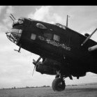
PeteH1969 Posted November 6, 2022 Share Posted November 6, 2022 All of theses were taken at RAF Cossford in 2005 https://i.postimg.cc/sgBsNhQw/DSCF0050.jpg Quote 2 Link to comment Share on other sites More sharing options...
theplasticsurgeon Posted November 6, 2022 Share Posted November 6, 2022 Italeri Apache Longbow a kit that I built OOB in 2020, without slaving to absolute accuracy. take any tips from the GB thread. 2 Link to comment Share on other sites More sharing options...
Brigbeale Posted November 6, 2022 Author Share Posted November 6, 2022 Many thanks to you both for the pictures. They’ll be if great help. The acrylic paint removed using airbrush cleaner. The plastic is not affected by it at all. 4 Link to comment Share on other sites More sharing options...
Gondor44 Posted November 6, 2022 Share Posted November 6, 2022 Although I have the much better Academy kit in the stash any information I get on building the aircraft will be good so I will follow this build if you don't mind. Gondor 1 Link to comment Share on other sites More sharing options...
Brigbeale Posted November 6, 2022 Author Share Posted November 6, 2022 37 minutes ago, Gondor44 said: Although I have the much better Academy kit in the stash any information I get on building the aircraft will be good so I will follow this build if you don't mind. Gondor You’re very welcome to follow along and chime in if you see anything obvious which looks out of place. I also have an Airfix 1/48 AH-46A in the stash. It was purchased by my stepson from someone reducing their stash. Although the box is showing some age and the paints are missing, the kit itself is still sealed in its original bag and the instructions and decals are present. Due to the size of it, I very much doubt if I’ll ever build it though. A size comparison of the 1/72 and 1/48 kits. 2 Link to comment Share on other sites More sharing options...
Brigbeale Posted November 7, 2022 Author Share Posted November 7, 2022 The cockpit tub was repainted using my airbrush. This time I used German Grey for the main colour, Medium Grey for the seats ad Dark Earth for the seat belts. The two instrument panels were painted matt black, with red, green and whit paint to give a touch of colour to switches and gauges - not even close to correct, but better than a blank black panel. The centre screens on each one was simply painted with French Blue. The control columns were also painted - they’re still on the sprue and will be added to the tub later. I also remixed my version of Zinc Chromate and applied that to the rotor mounting plate and the inside of the two fuselage halves where it locates. I think I will trim the forward instrument panel coaming a bit as it looks too long and hides the panel itself. For the cut out, I’ll add a small piece of sprue to emulate an electronic device fitted to the top of the coaming. 2 Link to comment Share on other sites More sharing options...
Brigbeale Posted November 8, 2022 Author Share Posted November 8, 2022 The control columns were added to the tub making sure of the orientation. They’re different lengths with the longer one fitting in the rear (pilot’s) position. The two instrument panels were then fitted. While waiting for the TET to set, I checked the instructions to see what was else needs fitting before the two fuselage halves get joined together. The only thing was the tail rotor bearing which was made up of two halves. The longer hollow part fits from the outside and the other part’s pin fits into it securing the bearing in position. It rotates, which is the main thing but it appears to be a slightly sloppy fit. If it looks too bad once the tail-rotor is fitted, it can be cemented into position to line it up. The observer’s forward coaming was cut back to a more aesthetically pleasing length and the cut out trimmed to make an even square recess for whatever filler piece I will fit later. With that fitted and another check to make sure I’d not missed anything, the cockpit tub was added to one side of the fuselage and then enclosed with the other half. The two halves wee then cemented together using TET section by section. Mostly, it went together five, but I had to force the tail section around the fuselage area upwards on one side to get it into line with the other half. Also the trailing edge of the fin needed some firm clamping/taping to get it to seal the gap. Then it was that nose section. I could hold it by hand quite easily, but for the longer term, I tried clamps, but they wouldn’t grip the curved fuselage (even the couple with wet/dry sanding sheets glued to the tabs wouldn’t stay put). I tried tape to pull one side but that kept letting go. I tried cable ties, but they wouldn’t stay put either. I even tried putting the nose in my small table mounted vice and then pulling the rear of the fuselage sideways enough to get the nose to line up, but I couldn’t get it to pull in the right spot. In the end I had to hold it for about 10 minutes and then wrap an elastic band around it. It’s almost there. The main section in top is ok, but the hole for the night vision/IR housing (which is moulded incorrectly - it’s moulded as a mirror image of what it should be. More work with the 3D printer there) is slightly out of line. I’ll see if I can persuade it into position later. With that done, the Apache was left in the stand to dry fully. And I bought another helicopter yesterday off EBay for about £4.00 +the same in p&p. 2 Link to comment Share on other sites More sharing options...
Brigbeale Posted November 9, 2022 Author Share Posted November 9, 2022 (edited) It was that time to take a brave pill and cut the rear of the sponsons off as a prelude to designing and 3D printing the more correct shaped replacements. I used my 2.5x magnification lenses on my headset to see what it was doing. First I applied a short piece of tape to the side of the sponson on the panel line and made sure it was straight. Nest came the moment of no return - the first cut. Using a fine saw with a reinforced spine, I made light saw cuts down to the fuselage. Then, using the tip of the saw, I scribed the lateral cut bit by bit until it was through and then then finished the pointed bit with a normal sawing motion. The first side went as intended apart from the fact I nicked the top horizontal line thinking I’ll have to repair that somehow, but in fact it’s only the mounting line for the engine/gearing exit/exhaust pods so will be hidden once they’re fitted. I used the same method for the port side using a panel line and that also came off neatly. Then I had to re-cut it as the panel line I had used was set further back than the starboard side by about 3-4mm and as a result, the two sides weren’t level with each other. Looking from the bottom, there’s a panel line which follows the second panel line further forward from the first cut line, so tape was put across it as a guide (there’s no matching panel line on the port side of the sponson itself). The distance was measured and a second piece of tape was place to mark the intended cut line. I recut the sponson so now the two sides match. That left me a probable issue with the way the sponson meets the curve of the fuselage underneath as part of it still angled up. The only solution I could see was to cut out another section out using the tape guide under the fuselage and the horizontal panel line on each side. For that, I used my Tamiya 0.1mm saw blade. Once all the sections were cut from the sponsons, the cuts were tidied up with a knife and file to remove most of the rough edges. Now I just need to design the replacements. What could possibly go wrong?😆 The nose section is set with the upper panel lines aligned, but the hole for the IR/PNVS sensor spindle is slightly off. I think the only option for that is to drill the hole bigger to make it a proper circle, fill it with a piece of round sprue and then later, re-drill it the correct size for the spindle. Edited November 9, 2022 by Brigbeale 2 Link to comment Share on other sites More sharing options...
Brigbeale Posted November 10, 2022 Author Share Posted November 10, 2022 (edited) Not a great deal of work was done to the Apache last night, as I was side-tracked with a friend’s VW LT/Mercedes Sprinter (same van with different badges on them) dashboard blanking plate which is no longer available new. So really, the only thing that I did manage to do was finish off fitting the gun mounting plate under the nose and fill the IR/PNVS (Pilots Night Vision Sensor) spindle hole. That was done with a round file to make the hole round and then a piece of melted sprue was pushed in and given a generous application of TET. once it was dry, the gap between the fuselage halves was filled with Revell Plasto filler, as was the ugly mark left on top of the fuselage by the oversized sprue gate. I’d previously set the front and rear edges at the correct level with the surrounding fuselage and glued it using TET and left it to set. Last night, I used a couple of small clamps to push the slightly bowed edged into alignment with the fuselage and used more TET on them. The panel now sits flush with the fuselage with some gaps to fill around it. Edited November 10, 2022 by Brigbeale 3 Link to comment Share on other sites More sharing options...
Brigbeale Posted November 16, 2022 Author Share Posted November 16, 2022 With some other things in life getting in the way of modelling done, I was able to get back to the Apache’s side pod conversion. Measurements were taken of the original and various photos were used to get an idea of the shape. Using Onshape, I came up with this design, which includes the contoured shape to fit around the fuselage underneath. It will probably need a couple of tweaks to get it to fully fit correctly, but it’s a starting point. I’ll 3D print them later and see how they fit later today. 2 Link to comment Share on other sites More sharing options...
Brigbeale Posted November 16, 2022 Author Share Posted November 16, 2022 I 3D printed the two D-model side-pod correction parts this morning and offered them up to the fuselage. For a first print they weren’t bad, less than 0.5mm too low. Rather than print another pair, I made the adjustments to the top of the printed parts and the kit pods. That bought the bottoms level. The tops had a slight step in them but otherwise they fitted quite well. There was a gap around the fuselage curve, but I expected that and planned to fill it anyway to hide the joint. Due to the limitations of the FDM type 3D printer and the awkward shape of the part, there were visible steps on the top where each layer was printed. I figure the solution would be to run a smear of filler over it. This would also take care of the step. The sided of the fuselage were masked around the shape of the pod corrections and filler was applied with a toothpick on the top, rear and bottom faces. Filler was also applied to around the under belly cannon mounting plate. Once it had dried sufficiently, it was all sanded back to smooth it out. All in all, the pod corrections have worked out well. I made a tweak to the design to make the rearmost rectangle more prominent just in case I may need it I future if I get another Apache. And with the ‘wings’ dry fitted. 5 Link to comment Share on other sites More sharing options...
Brigbeale Posted November 18, 2022 Author Share Posted November 18, 2022 Tonight, I started by assembling the control panel to the interior of the cockpit canopy and then masking the canopy itself. The canopy was then fitted to the fuselage which required a little but if trimming to allow it to sit in fully especially at the rear on the starboard side, as it kept pushing inwards when it was clicked into place. The main gear struts were both fitted as well. I used the images on the box to get an idea of where the gear is supposed to be angled at. I put a straight rod across the top of the rotor head hole to make sure the fuselage sits level. The engines were then assembled, which looked simple enough in the instructions. In reality though, they left a bit to be desired fit wise. The upper and lower halves could slide about against each other despite having location pins. There was also a fair amount of flash in the exhaust ports. Then front face where the front cowling fits needed levelling to allow said cowling to fit flush. To fit the engines, they required some material to be removed from the rear to allow them to sit flush on the fuselage, as did the front cowlings. Apart from that they fitted reasonably well. The stubby wings/weapons racks were also fitted. The port one fitted quite well with a nice firm fit. The starboard one, however, was a very loose fit and didn’t want to fit up against the fuselage. A little trimming of the inboard rear edge resolved the fit issue. 3 Link to comment Share on other sites More sharing options...
Brigbeale Posted November 22, 2022 Author Share Posted November 22, 2022 (edited) The engine upper and lower casings are a less than desirable fit. The port side had a definite step where the two halves met, especially near the exhausts. Some careful sanding to preserve the rivet detail mad them better but there’s a small dip in the lower half which will need filling. The starboard side wasn’t as bad, but still needed the attention of a sanding stick to even the top and bottom halves out. The exhaust outlets were tidied up with a flat file and then TET was painted on to tidy the filing ‘fluff’ Once they were done, I started adding the smaller detail parts to the fuselage. The tail mounted chaff dispenser was fitted, although I had to resort to the brilliant pictures supplied by @PeteH1969 to see exactly where it was placed as the instructions are more of a ‘somewhere about there’ kind of thing. The two vanes on top of the fuselage were fitted also - they went on with no problem even though, again it’s a guess where they sit as there’s no locating pins, holes or slots to fit them into. The horns either side of the rotor hub opening were fitted - yet again with reference to the photos. The gun mounting was fitted into position - that needed a part trimmed off as it wouldn’t allow the mount to fit in its hole. I left the gun off for now. The rotor blades were assembled once the ejector pin marks were taken care of on the hub. The blades themselves also had ejector pin marks on them which also need filing down. If they weren’t all different heights, I would have left them as some detail, but one was practically level so the others had to go. The rotor pitch actuator plate (if that’s what it’s called) appears to be fitted to the rotor shaft, which would be ok if the rotors would be glued on, but I prefer to have them removable (placed on dry). There’s detail on the blades which would appear to have a pin fitted which would to the the plate underneath, but there’s no pins supplied or holes in the plate itself. I might have a go at putting that to rights. The rotor mounted sensor was assembled and put aside to dry. The rocket pod bodies were assembled and left clamped to dry. They will need the seams sanding smooth. The ends will then be added. Once the rotor head sensor assembly was dried enough it was test fitted to the rotors which was in turn test fitted to the rotor shaft. The whole lot was the. Test fitted to the fuselage to see it all was ok. Edited November 22, 2022 by Brigbeale 6 Link to comment Share on other sites More sharing options...
Brigbeale Posted November 24, 2022 Author Share Posted November 24, 2022 Work continued on the Apache by adding various tiny appendages to the fuselage. At one point, I dropped the pitot tube which locates under the cockpit area next to the main gun mount. I was on my knees ferreting around for about a quarter of an hour combatting the carpet monster, as I was determined I was going to find it. Eventually - success! I then glued it in before it disappeared again. The upper cable cutter which fits on top of the canopy seemed too big when compared to the photos, so it was remodelled by snipping the top down and sanding the raw edges smooth. It looks more in keeping now. After a few views of the photos, I was debating whether to add the MWS and (what appear to be) side mounted chaff dispenser pods to the sides of the fuselage. In the end, I decided to try to make them. To start with, I figured it would be best to mark the positions with tape to give me an idea of the positions and how they would be affected by the curves on the the fuselage. This was done by adding small pieces of Tamiya tape to the various locations. Sketches were made using the photos as reference, and the tape for sizes. The first one (chaff dispenser pod?) was designed in Onshape. It looks ok - it’s only 7.5mm long x about 3mm at the base. Whether the printer will do the recesses remains to be seen, but if it doesn’t, I could probably print a decal for it. The plan is to 3D print all of the protrusions together -so fingers crossed! The fuselage itself had a couple of errant seam lines. They were sanded smoother and then the centre seam line was painted with Mr Surfacer 1000 to fill in any recesses where the two halves meet. A few sink marks and errand ejector pin marks were filled also. 3 Link to comment Share on other sites More sharing options...
Brigbeale Posted November 27, 2022 Author Share Posted November 27, 2022 The Mr Surfacer had dried on the fuselage seams and tonight I sanded them back with wet and dry sand-paper. That sorted out the seam lines/divots from sprue gates and areas where the parts didn’t quite line up with each other -although I’ve just noticed the front engine covers need a little work to fill them as well. It took me 3 attempts to get some half decent prints of the 3D printer for the various MAWS pods for the rear fuselage For some reason - it think it may a combination of dust and old(ish) filament - the prints weren’t as clean as I would have liked. I picked the best ones and cleaned them up with a file and sand-paper. Using sprue-goo, I fitted them to their respective locations on the fuselage. Once the sprue-goo has set, I can clean them up further, and where necessary, fill and sand them smooth. 2 Link to comment Share on other sites More sharing options...
Brigbeale Posted November 28, 2022 Author Share Posted November 28, 2022 (edited) The 3D printed parts had a smear of Vallejo plastic putty around them to fill the tiny gaps where they mounted to the fuselage. That was then cleaned up with a damp cotton bud. Looking at the pictures again, I decided to add the steps for access to the engines and the tail rotor. I have a roll of telephone wire where I each strand measures .48mm in diameter. I found a suitable tool and bent the wire around it. The first attempt around the small wooden leg was too wide, so a second attempt with a handle of a knife was a better size - they looked much better. 0.5mm holes were drilled in the appropriate places and the wire steps were placed in slightly too far out for the moment. Superglue was added just shy of where the wire entered the fuselage and then the steps were pushed in to the appropriate depth. The same wire was also added under the fuselage to make a vertical aerial on the tail section. A part number tag from the sprue had the numbers removed, trimmed, filed and added to the underside to from another antenna under the tail also. The Apache was given a clean with IPA to remove dust and any unwanted contamination. I then gave the Apache a coat of Halfords Plastic Primer. That improved the look of the model now everything is on one colour. Edited November 28, 2022 by Brigbeale 2 Link to comment Share on other sites More sharing options...
Brigbeale Posted December 1, 2022 Author Share Posted December 1, 2022 There were a couple of gaps at the rear of the canopy where it meets the fuselage. These were filled with Vallejo Plastic Putty. They filled well, but in the process, I managed to knock the top cable cutter off again🙄. It’s now in the storage tray for re-fitment later on as it’ll probably only get knocked off again. Next up was the rotor blade pitch device, or the fitment of it. Using the same wire as on the steps, I superglued 4 short lengths into the lower cross piece. These wires were then superglued to the ‘claws’ on the rotor head assembly. A test fit to the rotor shaft showed the result I was after. The rotor assembly can be removed if I want leaving the rotor shaft glued in position to the fuselage. With that assembled, the module which sits on top of the rotor was filled and sanded around the sides where the two halves met. Then it was a quick trip to the shed/workshop to give the rotor assembly parts a coat of Halfords Plastic Primer. The parts were put aside to dry off a bit while I got on with some other things. The two inner pylons were cut from the sprue and cleaned up of flash and seam lines. They were then fitted in position with TET. I assembled one of the missile racks and fitted that to the starboard pylon. I heard/read somewhere that Apaches in use with UK forces have a fuel tank fitted to the port inner pylon instead of another missile rack - obviously dependant on the mission at the time. - so that’s what I’m going to do with this one. More 3D printing to be done. The main gear wheels were cut from their sprue and cleaned up of heavy seam line and quite large sprue gates for the size of the parts. The ejector pin marks on the inside of the tyres were cleaned up and filled with Revell Plasto. Being so small, those areas will be left to dry until the next modelling session where they will be sanded back. The two wheels however, were test fitted to the main gear. There a nice snug fit, so they can stay there until I go to sand them. Some filler was also added to the top MAWS pods as I noticed in the photos, they were far from satisfactory in the finish. 3 Link to comment Share on other sites More sharing options...
Brigbeale Posted December 2, 2022 Author Share Posted December 2, 2022 It was finally time to break out the airbrush this evening. The first thing to do was paint the rotor hubs with a darkish grey - Mr Color EDSG was used. I’m happy with that. The colour call-out on the back of the box stated Olive Drab FS34087. A quick check through my colour comparison folder revealed that Mr Color H304 has the correct (for the Italeri call-out) FS number. I also bought a pot of Tyre Black (as the Revell Anthracite has finally had it) and some Mr Hobby Mr Paint Remover (for a later project). The Olive Drab was airbrushed onto the fuselage (after I had re-attached the upper cable cutter again). It appears to be a different green to what’s shown on the box, but with some weathering/staining it may tone down a bit. Overall though, I’m happy with the colour - it turns out, it’s practically the same colour as the initial plastic. The main gear wheels were sanded to smooth the filler out and then they were painted. I also had a couple of additions to the stash today. A previously owned Fujimi BAE Hawk - no decals or instructions. Also, while I was buying paints, I couldn’t resist the Arma Hobbies Hurricane IIC Tropical. 1 Link to comment Share on other sites More sharing options...
Brigbeale Posted December 3, 2022 Author Share Posted December 3, 2022 (edited) I masked the rotor assemblies off for the airbrushing of the rotor blades. I chose the tyre black for a bit of subtly. It looked ok when sprayed on, but as it’s dried, it’s gone a bit blotchy, so another coat is required - maybe with some flat black added to darken it a bit….. After looking at images of Apaches, it seems they’re mostly more of a darker Olive Drab. I mixed up a darker colour by using Mr Color Olive Drab 1 with some NATO Black added. I decided I would do the rivet/panel lines to simulate hot days sat in the sun. I thought it looked ok as I was airbrushing it on, but now seeing it all shaded up, I’m not so sure The idea was to have the top and sides bleached out on the panels between the rivets while the underside was more darker overall being shaded. As the paint has dried, the rivet line shading looks ok, but just not suited to the Apache. The underside however, looks more natural to the Apache’s panel work, so I’ll give the top a re-coat with the left over paint I mixed. Edited December 3, 2022 by Brigbeale 2 Link to comment Share on other sites More sharing options...
Brigbeale Posted December 4, 2022 Author Share Posted December 4, 2022 The colour of the upper surfaces in the photos is a lot brighter than the actual colour, but still it’s just a bit too light, so I gave the upper surfaces a very light coat of the darkened Olive Drab 1. It looks a whole lot better now. The rotor blades were repainted with a darkened Tyre Black. They look a lot better now with an even coat of paint applied. The main gear wheels were fitted and the Apache was placed on the stand while the TET sets. The rotor blade hubs had a black wash applied for highlighting. I had a peruse of the decal placement - of which there’s not many. The box art and the instructions are at odds with each other which the placement of some decals while missing others. The box art seems more of a generalised image. The Apache will get a couple of coats of floor polish tomorrow, so the decals can be applied. The rotor shaft was fitted but I had to sit the main rotors on top to make sure it was straight as the shaft just sits in a shaped area with no definite locating. For the sake of it, I dry fitted the tail rotor as well for a ‘see what it looks like’ moment. 2 Link to comment Share on other sites More sharing options...
Brigbeale Posted December 5, 2022 Author Share Posted December 5, 2022 (edited) The Apache has two coats of Astonish Floor Polish this morning and was left to dry for the decals to be applied. The decals went on with no issues using Humbrol Decalfix followed up with Micro Sol (I’ve run out of Micro Set having previously knocked the bottle over - I keep meaning to get another bottle - honest!) The Apache was set aside to allow the decals to settle. The clear sprue was brought out of the box to have the navigation lights sorted. On the sprue, they’re just two clear flat ovals. The Apache has a light unit either side with a lamp in the middle. My solution was to use a 1.2mm drill bit to make a recess in the centre of the reverse side of each oval. They were made the depth of the angled tip of the drill bit and stopped there as the plastic isn’t that thick and I didn’t want to break through the surface of them. A blob of red and a blob of green paint was placed in the newly made recess on each one. Once the paint was dry, I used Vallejo NMF to paint the reverse side as the backing of the light unit. These will be attached once the Apache has has it’s matt varnish applied and it’s dry. 4 of the available 8 rockets were cut from the sprue and cleaned up. A hole was drilled in the tail end for the exhaust outlet and also to give somewhere for a cocktail stick to be placed to enable painting. I toned down some French Blue with some EDSG to get the approximate colour of the rockets in the photos. The 4 rockets were painted and while I was about it, I used a cocktail stick to paint the simulated heads of the rockets in the the two pods. The remaining decals will not go to waste as the Mistercraft Cobra finally showed up this week. Not the seller’s fault - just the situation with importing and postal strikes and so on…… I looked at the contents of the cobra box. The plastic is the same as the Javelin I previously built. Parts need cleaning up due to flash/ mould marks/excessively big sprue gates on small parts. The instructions are ok and the colour call-outs are also ok for the most part - a couple of errors. The biggest blunder is the decals. Two options are available - U.S. Army or Spanish Marina. The decal sheet is missing decals but no worry, there’s an extra decal sheet with the missing decals provided. Great - right? Ah - no. The ‘United States Army’ decals are still missing as are the ‘Marina’ decals. At least I can use the ‘United States Army’ ones from the Apache sheet. Edited December 5, 2022 by Brigbeale 3 Link to comment Share on other sites More sharing options...
Brigbeale Posted December 6, 2022 Author Share Posted December 6, 2022 (edited) Matt varnish was painted on the Apache this morning to knock the shine off from the floor polish. It was put in the cabinet to dry for tonight’s activities. The overhead sensor pod was fitted to the main rotor assembly (which had also received a coat of matt varnish along with the 4 rockets). The rockets were fitted to the starboard rack. The navigation lights were fitted with Humbrol Clearfix. They look quite good. It was time for the gun to be mounted but it looked too bare. It was missing it’s protective framework. First the gun barrel tip was drilled with a fine drill. So, I made one from the copper telephone wire. I found a good image of one, sketched it and bent the wire to shape fo form the framework. superglue was used to fit the wire parts together around the gun itself. Once I was happy with it, the assembly was fitted to the carrier bracket using TET. While the gun assembly was drying, I sorted the fuel tank for the port inner pylon. I found a small sprue with 2 small fuel tanks and two rocket pods. The fuel tanks looked to be about the right size so one was pinched for the Apache. If I remember what I bought tanks/rocket pods for (maybe a BAE Hawk), I can always 3D print a replacement. The fuel tank was glued together and sanded around its seam. It was then fitted to the port inner pylon. Both the gun assembly and fuel tank were painted with Olive Drab paint and then given a coat of the darkened Olive Drab 1 paint. They blend in perfectly. The gun tip was painted with Vallejo NMF. The nose sensors had the ‘glass’ areas painted gloss black and a red pen was used around the rim to highlight the area. The tail wheel was painted with tyre black as I’d forgotten to do it when I did the main wheels. The canopy was unmasked - no paint creep👌 The tail rotor was glued on and finally the main rotor assembly was placed on top of the shaft - no glue - it can be removed for safety if required. And that’s about it - the Apache is finished. I love the way it’s turned out. I’ll try to get some better pictures for when I do the RFI write-up. Edited December 6, 2022 by Brigbeale 1 Link to comment Share on other sites More sharing options...
PeteH1969 Posted December 7, 2022 Share Posted December 7, 2022 Very Nice Well done 1 1 Link to comment Share on other sites More sharing options...

Recommended Posts
Create an account or sign in to comment
You need to be a member in order to leave a comment
Create an account
Sign up for a new account in our community. It's easy!
Register a new accountSign in
Already have an account? Sign in here.
Sign In Now