billn53 Posted July 25, 2022 Share Posted July 25, 2022 I usually post in the Aircraft forums at Britmodeller, but I loved the Mandalorian TV series and pre-ordered Revell's 1/72 Razor Crest as soon as I learned of it. @Andy Moore 's most excellent build ( https://www.britmodeller.com/forums/index.php?/topic/235103157-mandalorian-razor-crest/ ) prompted me to start one of my own. I seriously doubt I can do as fine a job as Andy, and I won't repeat here the work he has done. Instead, I'll focus on two areas that (I hope) will serve as a supplement to Andy's WIP: Lighting, and a few aftermarket 3D-printed parts. Here is an overview of my lighting plan for the Razor Crest. Not everything is "screen authentic", I've taken some liberties by adding a few lights that aren't shown in the TV series: The 3D-printed parts I am using all come from Shapeways. They include: Instrument console, by 308 Bits. This comes pre-drilled for fiber-optic lighting: Mando and his little companion, also from 308 Bits: 308 Bits LED mounts for the engine exhaust: More refined exhaust nozzles, by Scale Mark Models: and lastly, more detailed landing gear hydraulics, from Scale Mark Models: =================================================================== My first task was to address a few of the shortcomings in the Revell kit. All of these are covered in detail by Andy's WIP, so I'll just summarize them here: I sanded smooth the "pebbly" plastic (especially on the upper surfaces), and re-scribed the major panel lines: Filled in various sink marks, such as the one shown here on the lower part of the front nose panel: Modified and detailed the side cargo doors to eliminate the "toy-like" lower hinge: Chiseled-away Revell's extraneous "wedges" on the side detail of the engine pods: Again, there's nothing shown here that isn't already described in Andy's build. Next installment: Starting on the cockpit and fuselage lighting . . . - Bill 10 Link to comment Share on other sites More sharing options...
billn53 Posted July 25, 2022 Author Share Posted July 25, 2022 In preparation for the lighting, I first sprayed key interior areas with black rattlecan paint from the hardware store, to serve as a light-block: I then painted the cockpit overhead area in silver to enhance illumination of the interior: I am using a 9-volt battery for power, which will be located at the rear of the cargo bay and accessible via the rear cargo ramp: The cockpit deck is supported by a lower structure that includes various compartments, including what appears to be a latrine. I cut away portions of the lower structure to facilitate routing of LED cables and fiber optics (red arrow). I also removed the center part of the cargo bay floor to make way for the switch I'll be using to control the lighting. The switch is a simple on-off push-button, which will be mounted through the bottom of the Razor Crest's fuselage (green arrow). Here are the cockpit parts after painting: I mounted a 1.8mm cool white LED at the rear cockpit bulkhead. As an aside, I am using pre-wired LEDs wherever possible. My sources for the LEDs are Evan Designs ( https://evandesigns.com/ ) and Lighthouse LEDs ( https://lighthouseleds.com/ ) (Note that I also opened up the doorway leading to the vestibule behind the cockpit). The 1.8mm LED gives adequate light when viewed in a darkened room . . . . . . but is barely noticeable under normal room lighting. Andy had used a 3mm LED, which in retrospect I should have done as well. To increase illumination of the cockpit interior, I added a nano-size, warm white LED chip to the canopy framing, right over the seating and instrument console area: With the cockpit lighting done, I turned my attention to the nose exterior lights. I drilled out holes for the two red chin lights: and inserted from behind two "Z" size LED chips: I used clear, UV-actived acrylic to create lenses at the front of the lights. This also served to fix the LEDs in place: Voila! Chin lights done! - Bill 9 Link to comment Share on other sites More sharing options...
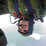
billn53 Posted July 25, 2022 Author Share Posted July 25, 2022 Next installment in my Razor Crest lighting adventure . . . . (And, no, I haven't done everything shown so far in a single day! I actually began a few weeks ago, and only recently decided to document the work in a WIP thread.) For the landing lights, I drilled holes in the back of the nose landing gear bay and installed a pair of 1.8mm cool white LEDs: I had to make a hole in the floor of the lower-level support structure, in order to clear the LEDs and their electrical leads: Here is how the landing lights look as viewed from beneath the Razor Crest: b =============================================================== Now for the most challenging part, by far, of my lighting effort: installing fiber optics to the instrument console! As I mentioned in my first post, the 308 Bits instrument console comes pre-drilled with holes for fiber optic cabling. (Well, they aren't actually drilled, but created during the 3D printing process.) The piece has more than 70 holes provided, but as I'll show, not all of them are useable. Curiously, 308 Bits did not include holes for the three prominent red lights on the portside console. I hand-drilled these, sized for 0.5mm fiber optics. (Most of the console's holes are 0.25mm diameter, with a few 0.5mm holes). There are a number of holes on the side consoles, but I found it impossible to thread fiber optics through them because the back of the holes are very close to a vertical panel. I found multi-colored fiber optics in 0.25mm and 0.5mm size on eBay, and bought enough for this project (and more) at a reasonable price. I "mushroomed" the ends with a hot blade in order to a) increase the light emission at the end of the cable, and b) prevent the cables from slipping through the holes during installation. I'll admit that the latter reason took priority in my thinking. Unhappily, I found that the mushrooming process eliminated the color in the emitted light, so that (for example) red cables emitted white light instead of red. To mitigate this, I resorted to painting the ends of the cables with colored, transparent acrylics after they were installed. This is the result of many hours of eye-watering, headache-inducing work: Not bad! My main disappointment is that the lights under the two large, blue panels on the front console, when lit, show up as individual lights instead of uniformly illuminating the panel, even through Revell's panel decals. ☹️ I also added a few (four) lights on the starboard side of the cockpit, based on screenshots from the TV series: In total, I installed (by my count) 45 fiber optic cables to the instrument console and starboard panel. That's a lot of fiber optic cabling to manage and route back to an LED illuminator. I decided the best approach would be to route the fiber optics under the cockpit deck, which meant I had to cut holes in the deck for the cabling: I also had to grind away part of the support structure to make room for the four cables I added on the cockpit's starboard side panel: You may be asking, "With so many fiber optic cables coming out of the instrument console, can any of them be seen?" This is the view through the canopy opening: Remembering that Mando is going to be sitting in the middle of the console, I expect the fiber optic cables will be mostly hidden from view. Just to be sure, I've since painted the parts of the cables that are above the cockpit deck with a dark gray color. That just about wraps up where I am with lighting Razor Crest's nose, cockpit, and instrument console. Next up: Lighting the engine pods. Thanks for viewing, and remember, any comments / suggestions are very welcome! -Bill 11 Link to comment Share on other sites More sharing options...
opus999 Posted July 26, 2022 Share Posted July 26, 2022 Wow, neat! This looks like it is going to be a fun build. I've never had the courage to try lighting something, but have been totally "wow"'d by some lit-up Star Trek ships. I have to confess that I haven't seen the Mandalorian yet, even though I really want to. I did get to see the Asokha episode though... oh and the part when Luke comes to get Grogu... but that's it... 1 Link to comment Share on other sites More sharing options...
billn53 Posted July 26, 2022 Author Share Posted July 26, 2022 1 hour ago, opus999 said: Wow, neat! This looks like it is going to be a fun build. I've never had the courage to try lighting something. . . . I've done a little bit of lighting work, but nothing near as complex as this project! And, I've never used fiber optic -- this is definitely a learning experience for me! (I sure hope it works out 😉 ) 1 Link to comment Share on other sites More sharing options...
Peter2 Posted July 27, 2022 Share Posted July 27, 2022 Bill, A very busy illuminated interior, which will add to the model's final impact. In earlier days when fibre optics were becoming used in modelling, I read that if the modeller painted the outside of fibre optic cables (with suitable paints, as some paint types might attack the material which the cable was made from) this could improve the light transmission properties of the cable. Is that still relevant advice? Also, which paints are OK to paint the cables with? 1 Link to comment Share on other sites More sharing options...
billn53 Posted July 27, 2022 Author Share Posted July 27, 2022 1 hour ago, Peter2 said: Bill, A very busy illuminated interior, which will add to the model's final impact. In earlier days when fibre optics were becoming used in modelling, I read that if the modeller painted the outside of fibre optic cables (with suitable paints, as some paint types might attack the material which the cable was made from) this could improve the light transmission properties of the cable. Is that still relevant advice? Also, which paints are OK to paint the cables with? I would expect water-based acrylics to be safe for painting fiber optics. But, to improve light transmission, the paint must be a color with high reflectivity (e.g., white or silver). [The purpose of the exterior paint is to reflect back into the cable any light that would otherwise be lost.] Link to comment Share on other sites More sharing options...
Peter2 Posted July 27, 2022 Share Posted July 27, 2022 (edited) Bill, Thanks for clearing that up. I wonder why don't the manufacturers coat the fibre optic cable? More cost? Edited July 27, 2022 by Peter2 Link to comment Share on other sites More sharing options...
billn53 Posted July 28, 2022 Author Share Posted July 28, 2022 1 hour ago, Peter2 said: Bill, Thanks for clearing that up. I wonder why don't the manufacturers coat the fibre optic cable? More cost? I presume it is because a) fiber optic cables are already very efficient (typically, around 1 decibel - less than 10% - reduction in light intensity per kilometer) and b) losses due to light leaving the cable are insignificant compared to other reasons for losing light (e.g., absorption and scattering of light within the cable itself). Good discussion here: https://www.fiberoptics4sale.com/blogs/archive-posts/95048006-optical-fiber-loss-and-attenuation - Bill Link to comment Share on other sites More sharing options...
billn53 Posted July 30, 2022 Author Share Posted July 30, 2022 I had a midterm exam in my Calculus 2 class yesterday, which kept me away from the bench for a couple of days. But, that's over now and I'm back to work! This update focuses on lighting the Razor Crest's two engine pods. Before doing anything else, I had to decide how to get the wires from the engine pods to the fuselage, where the battery will be. I drilled holes in the side of the upper pod halves, beneath the wedge that mounts the pod to the fuselage. I also drill holes in the top of the fuselage where the wedge sits. This way, I can route wires from the engine pods, beneath the mounting wedge, and into the fuselage -- all hidden nicely from view. I'm adding red two strobe lights to each engine pod. The specific lights I'm using are Evan Design's chip-sized "4-sync Breathing LEDs". This is a set of four LEDs wired so that they flash together. "Breathing" means that the light ramps slowly up and down over a 1-second period, instead of having a simple on-off flashing. I drilled 2-mm holes for the red strobes in the top and bottom of each engine pod. Because the 4-sync LEDs are all wired together, I added a connector between the LEDs for the two engine pods. This allows me to work on each pod individually, without them being tied together by the electrical wires, and making the necessary electrical connections during final assembly. I fixed the LEDs in place using UV-activated clear acrylic, I then covered the LEDs and their wires with packing tape (not shown) for added reinforcement: The engine pod's plastic is pretty thick where I added the LEDs, and I will need to fill the holes yet still transmit light to the surface. I have two options in mind: a) use clear UV-activated acrylic (like I did with the chin lights), or b) insert a short segment of 2mm fiber optic cable in the hole. The latter option is shown below, and works like a champ. I'll decide later which approach to use. With the strobe lights in place, I next tackled the engine exhausts. I first had to open up the rear of the engine structure: I found the 5mm LEDs I'm using to be a tight fit in 308 Bits engine mounts, and had to enlarge the holes with a drill bit. Also, the mounts are printed using a translucent resin, and I don't want any light escaping through the side of the engine pods. To prevent this, I first painted the backside of the mount white: then applied a thick layer of black paint over the white: I experimented with a number of different types of LEDs for the engine exhaust, and settled on a configuration with one yellow LED in the center location and six orange "flicker" LEDs in the outer ring. In my mind, this gives an impression of the engines idling on the ground at low power. Here's the package all wired together and installed in the engine pod: That done, all I had left was to glue the engine pods together, do a final check of the lights, and a test fit of the engine pods to the upper fuselage half: The approach I've taken for the Razor Crest's lighting has the advantage that I can work on major sub-assemblies individually. I can paint, detail, and weather the engine pods prior to mounting them to the fuselage. Likewise, I can put a base coat of paint on the top and bottom fuselage sections before assembling them. I'll add the cockpit and lighted instrument console to the lower fuselage half and complete the fiber optic work. I'll then attach the engine pods to the upper fuselage half, complete the remaining electrical work, and close-up the fuselage. 8 Link to comment Share on other sites More sharing options...
Thom216 Posted July 30, 2022 Share Posted July 30, 2022 Bringing the Razor to life! Looking good. 1 Link to comment Share on other sites More sharing options...
billn53 Posted August 1, 2022 Author Share Posted August 1, 2022 Base color coat is on all the major pieces. I "primed" with thinned Mr. Surfacer 1200, then sprayed Alclad II Duraluminum. Once this is dry, I'll add a protective coat of Alclad Aqua Gloss before starting any weathering. 6 Link to comment Share on other sites More sharing options...
billn53 Posted August 1, 2022 Author Share Posted August 1, 2022 While waiting for the Alclad Aqua Gloss to dry, I began assembly and painting of the landing gear pieces. The 3D printed hydraulic actuators on top of the main gear are a significant improvement over the kit parts, but definitely on the pricy side: Once the Aqua Gloss had dried, I couldn't resist piecing together the fuselage and engine pods: She's starting to look like a spaceship! 🚀 8 Link to comment Share on other sites More sharing options...
opus999 Posted August 2, 2022 Share Posted August 2, 2022 Wow, that looks pretty cool with the duraluminum. I can only imagine that combined with the LEDs! 🤩 1 Link to comment Share on other sites More sharing options...
billn53 Posted August 2, 2022 Author Share Posted August 2, 2022 Weathering of the duraluminum finish has begun! I began by doing a dark gray panel line wash. Boy, this puppy has a lot of panel lines, it seemed to take forever! Next, I applied a basic Flory wash (my go-to for projects like this). Flory is a water-based clay suspension. It looks like cr*p when going on, but when applied over a gloss finish wipes off easily with a damp cloth. I found that gentile "patting" motion with the cloth gave me good control over how much of the wash was removed. Here it is before cleaning: and after: I may yet add some more Flory to areas that look too clean. Once I'm happy with the base weathering, I'll fix the Flory in place with another clear coat, and begin more detailed work with oils, enamels, and perhaps some pigments. 7 Link to comment Share on other sites More sharing options...
Pete in Lincs Posted August 2, 2022 Share Posted August 2, 2022 On 8/1/2022 at 4:09 PM, billn53 said: She's starting to look like a spaceship! Looking rather fabulous is what it is! I seem to have missed the start of this one but I've caught up now and I'm very impressed. The wiring etc has taken a great deal of forethought by the look of it. The lighting looks great. 1 Link to comment Share on other sites More sharing options...
billn53 Posted August 3, 2022 Author Share Posted August 3, 2022 Testing to see if I can post videos from Flickr. Let me know if it works! Thanks, Bill 5 Link to comment Share on other sites More sharing options...
neil5208 Posted August 3, 2022 Share Posted August 3, 2022 Works mate 1 Link to comment Share on other sites More sharing options...
billn53 Posted August 4, 2022 Author Share Posted August 4, 2022 A bit more progress to report . . . I thought it best to add the exterior decals before going any further with weathering. The decals went on without any problems, and settled in nicely with some Solvaset encouragement! I re-scribed the panel lines covered by the decals. This took some special care, to prevent the decals from tearing. I discovered that applying a bit of Solvaset would soften the decal and make the scribing job easier. I'll next clear-coat the decals, touch up the panel lines with a wash, and do the Flory magic to blend in the decals with the weathering I've already done. On the lighting front, I assembled the cockpit pieces and added them to the support structure. and gathered up all the fiberoptics into a piece of shrink tubing: I'm using a 5mm warm white LED to illuminate the fiber optics. I inserted the LED into a piece of shrink tubing, slipped the opposite end over the fiber optic bundle, and applied heat to complete the assembly. A quick test confirmed that the instrument panel lights are working properly 🙂 Last, but not least, I did some detail painting on the Razor Crest's occupants: The little green guy is just 5mm tall, so that's the best I could do! 11 Link to comment Share on other sites More sharing options...
Uncle Monty Posted August 4, 2022 Share Posted August 4, 2022 This is looking absolutely EPIC, well done sir. The lighting effects are spot on and well worth the hours you've put in. 1 Link to comment Share on other sites More sharing options...
billn53 Posted August 7, 2022 Author Share Posted August 7, 2022 It's the last week of summer session and I have a Calculus 2 final coming up on Thursday. Then, next week, I'll be on a business trip to Alabama. So, building will be slow for the near future. Nonetheless, I am making progress . . . Weathering the Razor Crest continues. I added some dust & sand effects to the landing gear: Then, spent a few hours of quality time using oils on the engine pods: After the oils had dried, I added lenses for the engine pod strobes. I made these from very short pieces of 2mm fiber optics. Recall that the red LEDs are attached to the inner surface of the pods -- the fiber optics should work to bring the light out to where I want it: Click below for a short video showing the synchronized strobes in action: Once again, I couldn't resist piecing the major sub-assemblies together, just to see how she's looking. Next up: Connecting all the electrical parts together and closing the fuselage. 10 Link to comment Share on other sites More sharing options...
opus999 Posted August 7, 2022 Share Posted August 7, 2022 WOW!!! This is going to be fantastic! The videos are a nice touch -- they really help visualize the final product. 1 Link to comment Share on other sites More sharing options...
billn53 Posted August 8, 2022 Author Share Posted August 8, 2022 It's been a rainly Sunday and, after getting caught up on my weekend math assignments, I glued the cockpit assembly (fiberoptics and all) into the lower fuselage half: As you can see, I've quite a mess of spaghetti building, . . . and a means of managing the internal wiring is needed. I began by soldering together a set of connectors: The main wire (on the right) will go to the battery, the five on the left to each of the major subassemblies -- fuselage lower half, port and starboard engine exhaust LEDs, the synchronized strobes, and lastly the little chip-LED I added at the top of the cabin. By using connectors, I minimize the amount of soldering needed internal to the fuselage, and will be able to wire the top and bottom fuselage assemblies separately, and connect them together when I close the fuselage. That's my plan, at least! I had previously drilled a hole at the bottom of the fuselage for my power switch: Here's the switch in position. Note that I've epoxied a large nut at the bottom of the fuselage. I've threaded the battery ground wire through the nut. This should minimize the possibility that one could accidently pull the switch, and all the internal wiring, out of the interior when changing the battery! The switch fits nicely, and with a bit of paint should blend in well with the Razor Crest's busy bottom-side: Access to the battery is through the rear cargo door. To secure the door when shut, I added a magnet at the top of the opening and a strip of ferrous metal to the top edge of the door: Test of the lower fuselage wiring & lighting . . . . Test sat! 😃 I added connectors to the wires coming out of the engine pods, then glued the pods into position. A bit of tape helps keep the wiring under control: Total system test of the wiring & lighting. (Must remember: Red goes to Red, Black to Black!): System test complete! Test sat! 🥳 🎉 It's nearly time to close the fuselage. But first, I had to do a few final, but essential, additions to the cockpit: Cheers! -Bill 8 Link to comment Share on other sites More sharing options...
billn53 Posted August 9, 2022 Author Share Posted August 9, 2022 Well, the fuselage is finally closed up, but she put up a bit of a fight! The fuselage top, at the front, didn't want to mate with the bottom piece. It appears the top part had a slight warp to it. Some clamps, and goodly amounts of Bondene, got the parts together but with some gaps: Not pretty, but hey! This is the Razor Crest -- not exactly an example of pristine spacefaring! A smear of putty, and some touch-up with the airbrush, and everything will be fine! Trust me . . . . 13 Link to comment Share on other sites More sharing options...
opus999 Posted August 13, 2022 Share Posted August 13, 2022 Very clever there with the switch and battery access! 1 Link to comment Share on other sites More sharing options...

Recommended Posts
Create an account or sign in to comment
You need to be a member in order to leave a comment
Create an account
Sign up for a new account in our community. It's easy!
Register a new accountSign in
Already have an account? Sign in here.
Sign In Now