e8n2 Posted March 24, 2022 Share Posted March 24, 2022 It has been a long time since I first got this kit, and a long time since I've built a vacuum form kit. The first thing to do of course is to cut out the parts. Most people prefer to leave a little bit of an edge around the parts so that you can have an idea of how much more plastic is left to be sanded off to get to just the part itself. Others prefer to cut the parts out right at the edge of the part and just sand the little bit of the thickness of the plastic. If you decide to do it that way, you have to be extra careful so that you don't sand off too much and ruin the kit. Ask me how I know! For this one I decided to go with an edge around the parts. You will notice on some of the parts the edge is gone, That sometimes happen no matter how careful you try to be. I will have to be extra careful on those parts. It is also a good idea to keep some of the excess plastic in case you need to make spars, extra bulkheads, or tabs to put in along the fuselage top and bottom to help to ensure that the two halves line up correctly. The kit also comes with some white metal parts for the landing gear and props. It also has some decals, but these have probably gone bad by now. However I will be using a "Cut then Add" decal sheet for the Savage, and it comes with some of the wing walk markings so I'll be alright on that point. I will be doing the bomber version but will not cut off the photo nose until after the fuselage sides have been sanded out. Till the next update Later, Dave 16 Link to comment Share on other sites More sharing options...
heloman1 Posted March 24, 2022 Share Posted March 24, 2022 Wow, a blast from the past! I remember it in it's original boxing, pre Hannant's and may even have owned one. They were well engineered kits a very accurate. Mt preferred method of sanding ack the cut edge is to use a 1" Warding file. I work an area of a couple of inches at a time, this reduces the risk of error or over sanding. Good luck with your build, I'll tag along. Colin 1 Link to comment Share on other sites More sharing options...
theplasticsurgeon Posted March 24, 2022 Share Posted March 24, 2022 Nice one Dave, can't have too many Savages. Here's a link to this model that I built last year. Lots of new skills learned during that build. Wishing you luck with this project, I'm following it with interest. 12 Link to comment Share on other sites More sharing options...
Tailspin Turtle Posted March 24, 2022 Share Posted March 24, 2022 (edited) It's a very nice kit. Gordon did great work. Unfortunately, whoever added the propellers didn't pay close enough attention to those on the Savage or didn't care to (they look more appropriate for a turboprop airplane than the AJ). Another less notable niggle is the length of the canopy. For more including a comparison of the kit prop and the one on the AJ, see https://tailspintopics.blogspot.com/2021/03/north-american-aj-savage-model-kits.html Edited March 25, 2022 by Tailspin Turtle 1 Link to comment Share on other sites More sharing options...
e8n2 Posted March 25, 2022 Author Share Posted March 25, 2022 13 hours ago, Tailspin Turtle said: It's a very nice kit. Gordon did great work. Unfortunately, whoever added the propellers didn't pay close enough attention to those on the Savage or didn't care to (they look more appropriate to a turboprop airplane than the AJ). Another less notable niggle is the length of the canopy. For more including a comparison of the kit prop and the one on the AJ, see https://tailspintopics.blogspot.com/2021/03/north-american-aj-savage-model-kits.html I was not aware of the problems with the props and will try to get some replacements. I want to try and add at least the engine cylinders since they would be showing up a bit behind the prop. I am also working on a Mach 2 C-131D. I bought some resin replacement engines but have decided instead to use the engine fronts from the Italeri A-26K (they have a hole in the middle where as the resin ones had a splined shaft and the kit props already have a shaft. The resin engine fronts will go with the A-26K it instead. Any suggestions as to what other aircraft had the same props as the Savage? Hopefully there will be some aftermarket props that can be substituted for the kit one. The other problems with the size of the tail surfaces I'm just going to have to let go. It's a little beyond me to fix. Later, Dave P.S. I got the bomber nose sanded out today when I had a little time after working on some other projects. More photos after I make some more substantial progress. 3 Link to comment Share on other sites More sharing options...
e8n2 Posted March 31, 2022 Author Share Posted March 31, 2022 Some progress has been made! I have the left side fuselage sanded out. Took a bit over an hour and a half over two days to do it. I have several other projects going on as well but by the end of next week I should be able to spend more time on the Savage. I want to get both fuselage halves sanded out and the kit bulkheads installed. After looking over Tommy Thomason's site last night for pictures of the AJ-2 cockpit I will need to make some modifications to the kit's cockpit to include a little bit of scratchbuilding. Later, Dave 3 Link to comment Share on other sites More sharing options...
e8n2 Posted April 12, 2022 Author Share Posted April 12, 2022 More pictures and an update. I have now sanded out the right side fuselage, the exhaust pipe for the J33 engine, and glued the two kit supplied bulkheads into the fuselage. Here you will notice that I have also put in two locating tabs located mid fuselage to help to properly align the two fuselage halves. Using a piece of excess plastic sheet trimmed away from the parts, I aligned both halves of the exhaust and glued them together. I used some thin plastic strips to make alignment tabs for the bomber nose as well. The cockpit as supplied in the kit is inaccurate. Using the photos from the Tail Spin Topics blog as a reference, I cut out the left side aft seat riser. Part of the cockpit floor will be cut away, and a lower floor level with the bottom of the crew entry door will be put into place. Not sure exactly how I'm going to do the leaning ladder floor, but I'll figure something out. I used some resin remnant blocks to fabricate a center console and also made up a new seat riser for the Bomb/Nav seat. The center console has not been glued in yet and I may need to make an adjustment to the B/N seat riser's position. I also added a piece of scrap plastic sheet to fabricate the crewchief's panel. I will have to cut and sand the upper right edge to fit after the glue has dried. https://tailspintopics.blogspot.com/2013/04/aj-2-savage-cockpit.html When I did a test fit of the fuselage halves after the two bulkheads were installed I noticed that there is a gap of about 3/32" at the forward bulkhead, but no gap at the rear bulkhead. I will have to trim the front bulkhead so that the two halves line up correctly. I will also need to test fit the cockpit, minus the seats into the fuselage to see where exactly to cut out the cockpit opening. I also need to check to see what color to paint the cockpit area. It will probably be interior green and black. More to follow! Later, Dave 7 Link to comment Share on other sites More sharing options...
TonyW Posted April 12, 2022 Share Posted April 12, 2022 I'm in for the duration! I'm looking forward to seeing things come together here. I built one a while back and although it ended up completely different to what I initially planned, I really enjoyed the build. Here's the build... Link to comment Share on other sites More sharing options...
sammy da fish Posted April 12, 2022 Share Posted April 12, 2022 Nice start to your build there. And interesting vaccform model with a bit of effort they go together well. I have a resin one of these that I must pass on as my interests have changed over the years. sammy Link to comment Share on other sites More sharing options...
Tailspin Turtle Posted April 12, 2022 Share Posted April 12, 2022 "leaning ladder": The stairway up to the flight deck was basically a slanted piece of sheet metal with recesses for steps. For bailout expediency, the crew members would slide down to the lower deck, get to their feet, and go out the hatch. The B/N's seat back was hinged so it flopped all the way back, making it easy for him to access the "chute" and get it out of the way of the pilot. The third crewman might have elected to take a short cut by just jumping down from the flight deck to the lower deck. Link to comment Share on other sites More sharing options...
LorenSharp Posted April 12, 2022 Share Posted April 12, 2022 I'm in for for watching this build. I have the Combat Models 1/48 version in the wings waiting to be built., I know it will be a pain in the backside to build and correct, So I'm going to take bunches of notes on this one. Link to comment Share on other sites More sharing options...
e8n2 Posted April 13, 2022 Author Share Posted April 13, 2022 14 hours ago, Tailspin Turtle said: "leaning ladder": The stairway up to the flight deck was basically a slanted piece of sheet metal with recesses for steps. For bailout expediency, the crew members would slide down to the lower deck, get to their feet, and go out the hatch. The B/N's seat back was hinged so it flopped all the way back, making it easy for him to access the "chute" and get it out of the way of the pilot. The third crewman might have elected to take a short cut by just jumping down from the flight deck to the lower deck. I was trying to think of the best way to describe it. Your way sounds better. Making the recesses will be something else again, but we'll see what I come up with. Your blog post and pictures have been invaluable for the cockpit. Later, Dave Link to comment Share on other sites More sharing options...
Brandy Posted April 13, 2022 Share Posted April 13, 2022 This looks interesting. For cutting out the parts, mark around them with a thin marker pen. When you remove them from the sheet you can see easily where the sanding needs to go to. Not sure how that philosophy for bailing out would work in practice. Presumably if you have to bale out the aircraft is seriously damaged and you may not/probably won't be able to slide comfortably down a nice smooth surface because the aircraft is not straight and level, or even close to it. In fact you night even "slide" upwards, away from the exit!! Ian Link to comment Share on other sites More sharing options...
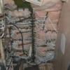
e8n2 Posted April 17, 2022 Author Share Posted April 17, 2022 More photos and another update. As you can see I have now cut off the photo nose. It has been removed from both sides. I also drew in where, for the sake of a better term, the avionics bay floor should be. Very little will be seen once the model is complete so actually I have made it a bit bigger than it needs to be and it has been glued into the right fuselage half. I have made some more progress on the cockpit area which will be discussed later. Here is the left side fuselage minus the photo nose. The nose gear wheel well has also been sanded out and will need some of the sides and front and back removed so that it will fit properly in the fuselage and not interfere with the avionics bay floor. Here is a close up of the cockpit floor. the area around the cockpit entrance door has been cut away, the intrument panel glued in, and the center console installed. It might not look the greatest, but this is the first time I've scratch built one. I had to move the Bomb/Nav seat riser and it will need a little bit of trimming. I also drilled a hole for the control column. I am planning on painting the cockpit interior green with the intrument panel, center console, B/N panels after I can come up with some stuff that will look convincing will also be black. This shows more of the cut out area and now the crew chief's panel has been trimmed to fit. Using some thin strip plastic and a little bit of Micro Krystal Klear, I have added the knobs to the top of the throttles. Why are there six of them there you might ask. I am also working on a Mach 2 kit of the C-131D. I am also going to scratch build a center console for that as well and it needs four throttles, two for each pilot. I used mini clothes pins to hold them upright until the Krystal Klear dries. I got a bag of about 50 of these little buggers at an arts and craft store and they can come in handy. Krystal Klear seems to basically be white glue. I have used it to tack in parts until later when I go back and use regular glue. This is the strip plastic that I used for the throttles. Not sure how widespread the availability of Evergreen plastic is in other parts of the world, but at least you can see the size that I used. Next week I will be out of town visiting family so nothing will be happening until the last week of April. Later, Dave 4 Link to comment Share on other sites More sharing options...
heloman1 Posted April 17, 2022 Share Posted April 17, 2022 Evergreen have a great range of plastic strip, rod, and other sections not to mention their sheet styrene. Well worth getting hold of their catalogue, a must fr any scratch-builder/detailer. Colin 2 Link to comment Share on other sites More sharing options...
e8n2 Posted April 29, 2022 Author Share Posted April 29, 2022 Time for another update. I already know that I am going to have to replace the props. The kit props are, as you can see in the photo below, about 14 1/2 feet in diameter, which matches a drawing in the Ginter book for the AJ-1. However, besides the blades seeming to be too wide, the spinner seems too wide and short. From the photos I have checked it seems the spinner was a little narrower, longer, and pointer. I was planning to replace the kit props with an aftermarket set for the P2V, but might have to rethink that since those have a smaller diameter. I also managed to get the nose gear well adjusted for proper height and glued in this afternoon. The kit nose gear wheel wheel is too wide and not tall enough. Re-checking photos showed that part of the wheel well made it up into the avionics bay. I had already sanded it down to fit into what I had, so it will have to stay that way. I also cut out the door that is normally open when the gear is down and drilled a hole to put the nose gear in when the time comes. It is offset slightly to the left of the centerline as per photos. I can also tell already that is it going to need a good amount of weight in the front to sit on it's gear. The bomber nose should be able to handle it all. I have decided that for the time being, Saturdays will be sanding Saturdays until I get the rest of the parts sanded out. Later, Dave 5 Link to comment Share on other sites More sharing options...
Tailspin Turtle Posted April 29, 2022 Share Posted April 29, 2022 On 4/17/2022 at 1:11 AM, e8n2 said: More photos and another update. Here is a close up of the cockpit floor. the area around the cockpit entrance door has been cut away, the intrument panel glued in, and the center console installed. It might not look the greatest, but this is the first time I've scratch built one. I had to move the Bomb/Nav seat riser and it will need a little bit of trimming. I also drilled a hole for the control column. I am planning on painting the cockpit interior green with the intrument panel, center console, B/N panels after I can come up with some stuff that will look convincing will also be black. This shows more of the cut out area and now the crew chief's panel has been trimmed to fit. Later, Dave Minor detail - aft of the bottom of the stairs leading up to the flight deck, the opening in the flight deck floor actually widens on a straight line from that point to the aft cockpit bulkhead. The right side of the third crewman's instrument/switch panel (left side from the aft-facing crewman's standpoint, is actually out over the opening; the flight deck floor is just wide enough for the third crewman's feet. See the cockpit link that you posted above. Link to comment Share on other sites More sharing options...
e8n2 Posted April 30, 2022 Author Share Posted April 30, 2022 14 hours ago, Tailspin Turtle said: Minor detail - aft of the bottom of the stairs leading up to the flight deck, the opening in the flight deck floor actually widens on a straight line from that point to the aft cockpit bulkhead. The right side of the third crewman's instrument/switch panel (left side from the aft-facing crewman's standpoint, is actually out over the opening; the flight deck floor is just wide enough for the third crewman's feet. See the cockpit link that you posted above. I noticed earlier that the stairway is wider at the top than at the bottom which I take is because the nose gear wheel well is wider at the bottom than the top. I'm sort of stuck with what I have there but I may be able to finagle something to account for the change in width of the stairway. I can cut back on the cockpit floor to get it more to the proper width at the crew chief's position. Thanks for the heads up! Later, Dave Link to comment Share on other sites More sharing options...
e8n2 Posted April 30, 2022 Author Share Posted April 30, 2022 Another update and a couple more photos. I finally decided I was at the point where I needed to open up the areas of the fuselage halves covering over the cockpit. Previously I had penciled in the area to clear out on the right side fuselage half. I taped the two sides together temporarily to make a cut on the left fuselage half at the rear of the cockpit opening. Using my sprue nippers I made some cuts towards the outside edge of both fuselage halves. After that I ran the blade from a larger Xacto knife. Using needle nose pliers I started bending each section gently back and forth until the piece came off. After both sides were done I then trimmed, scraped, and filed till I got the open in both halves to match the best I could or as far as I was willing to go. I did some test fitting of the cockpit floor in the fuselage and even though I hadn't planned on it originally, I decided I wanted to put in a left side console for the pilot's position. I will be using another resin remnant for that. I've marked the inside of the left fuselage where the bottom of the console needs to go. I need to check photos to see where the console ends and get it the correct length and heighth. Tomorrow being the first sanding Saturday, I plan on sanding out the seats and horizontal tail surfaces. I still need to do the leaning floor/stairway. After that I should be able to paint the cockpit. I also need to make one more throttle lever for the jet engine. Overall I felt like I had made some good progress on it today. By the by, the two control columns to the left of the fuselage are for the Mach2 C-131D. I used rod plastic to replace the terrible kit pieces. I still need to fabricate a control wheel for the Savage which is of a totally different design. Later, Dave 1 Link to comment Share on other sites More sharing options...
Tailspin Turtle Posted April 30, 2022 Share Posted April 30, 2022 (edited) 10 hours ago, e8n2 said: I noticed earlier that the stairway is wider at the top than at the bottom which I take is because the nose gear wheel well is wider at the bottom than the top. I'm sort of stuck with what I have there but I may be able to finagle something to account for the change in width of the stairway. I can cut back on the cockpit floor to get it more to the proper width at the crew chief's position. Thanks for the heads up! Later, Dave The stairway is a constant width. It's only the flight deck and the partial wall between the bottom of the stairway and the opening to the equipment bay under the flight deck that are angled. Edited April 30, 2022 by Tailspin Turtle grammar Link to comment Share on other sites More sharing options...
e8n2 Posted May 1, 2022 Author Share Posted May 1, 2022 13 hours ago, Tailspin Turtle said: The stairway is a constant width. It's only the flight deck and the partial wall between the bottom of the stairway and the opening to the equipment bay under the flight deck that are angled. From the photos it looks like it gets narrower from top to bottom, but maybe it is the way that the padding is sitting right there at the bottom of the ladder. From the photo looking into the under deck area directly across from the crew entry door, it looks like the flight deck floor may be angled in from about the crew chief's seat to the rear cockpit bulkhead. I just noticed that the top view looking down towards the entrance door shows that so I can fix that on Monday. No modelling work gets done on Sundays as it is my laundry day. I also noticed in the head on shot of the ladder that there appears to be an inner wall that comes down the side of the cockpit on the B/N side and ends just around the end of the ladder and is slightly separated from the fuselage sidewall. I should also be able to get that installed before starting to paint the cockpit. It may take a bit but I'll get `er done! Later, Dave Link to comment Share on other sites More sharing options...
Tailspin Turtle Posted May 1, 2022 Share Posted May 1, 2022 12 hours ago, e8n2 said: From the photos it looks like it gets narrower from top to bottom, but maybe it is the way that the padding is sitting right there at the bottom of the ladder. From the photo looking into the under deck area directly across from the crew entry door, it looks like the flight deck floor may be angled in from about the crew chief's seat to the rear cockpit bulkhead. I just noticed that the top view looking down towards the entrance door shows that so I can fix that on Monday. No modelling work gets done on Sundays as it is my laundry day. I also noticed in the head on shot of the ladder that there appears to be an inner wall that comes down the side of the cockpit on the B/N side and ends just around the end of the ladder and is slightly separated from the fuselage sidewall. I should also be able to get that installed before starting to paint the cockpit. It may take a bit but I'll get `er done! Later, Dave Oops - I just noticed that the North American drawing of the flight deck and "ladder" is misleading. There is no vertical panel along the side of the flight deck aft of the stairwell. There is a short vertical athwart-ship panel to the left of the stairwell, which does appear to be slightly tapered in width because its inboard side is slightly angled to the right from top to bottom. In other words that short vertical panel which is part of the support of the flight deck is not a rectangle. Link to comment Share on other sites More sharing options...
e8n2 Posted May 2, 2022 Author Share Posted May 2, 2022 11 hours ago, Tailspin Turtle said: Oops - I just noticed that the North American drawing of the flight deck and "ladder" is misleading. There is no vertical panel along the side of the flight deck aft of the stairwell. There is a short vertical athwart-ship panel to the left of the stairwell, which does appear to be slightly tapered in width because its inboard side is slightly angled to the right from top to bottom. In other words that short vertical panel which is part of the support of the flight deck is not a rectangle. Yeah, that is what I take for the actual nose gear wheel well which the kit got wrong. I just figured it out what the problem is. After a long look at picture 8 of 13 for the AJ-2 cockpit I noticed that the ladder is, until the very bottom step at the floor of the avionics bay, a trapezoid! The whole thing is leaning to the left along with the nose gear wheel well. The padding at the bottom of the panel also helps to make it look like it is narrower at the bottom than the top. This will be something to try to duplicate, but I'll give it a try. It's not like I'm doing this on a deadline. Later, Dave Link to comment Share on other sites More sharing options...
e8n2 Posted May 5, 2022 Author Share Posted May 5, 2022 Another update and a couple more photos. This past Saturday was my first Sanding Saturday, and I was able to sand out all three seats and two of the four horizontal stab pieces. The one picture I took was for a way to sand out flat pieces like wings, bulkheads, tail surfaces not already a part of the fuselage, gear doors and the like. A length of masking tape makes a handle to at least get started on sanding the part out. Those of us who have done vac kits before are probably already aware of this, but for the youngsters who have never done one before, now you know about this. As always, because nobody is perfect, there will be an area that is done before the rest and then you go to concentrate on sanding those areas out until all of the part is done. Tommy Thomason and I have been discussing the shape of the cockpit floor as you've probably seen. I inadvertently cut off too much of the floor so I've been working on adding some more to the floor so I can cut out the correct amount of the floor. Today since I had just glued in the replacement section of the floor, I decided to open up the jet exhaust area of the rear fuselage. Besides, it needs to be done before I can join the fuselage halves anyway. I also sanded out the engine exhaust shroud. I looked through my spare parts bin and found three partial burner cans with the flame holders that probably came from an F-4 kit. Tomorrow I plan on cutting away most of the one can I'm going to use and glue it onto the exhaust shroud. Once that is good and dry I'll trim it down some more so it will fit into the kit's exhaust assembly. Later I'll paint it with some Model Master Metalizer Exhaust. Before painting the model I'll stuff some kleenex into the opening. That's all for now. Later, Dave 2 Link to comment Share on other sites More sharing options...
e8n2 Posted May 8, 2022 Author Share Posted May 8, 2022 Another Sanding Saturday and a couple of more photos. I was able to get the remaining two pieces of the horizontal tail surfaces sanded out and also got the left wing armpit sanded out (that would be the bottom of the left wing between the fuselage and engine nacelle). I also got some painting done on it as well. The flame holder and exhaust shroud turned out very well. so all of the jet engine parts and areas of the rear fuselage were painted with Model Master Exhaust paint today. I'll glue the flame holder into the engine shroud on Monday. I may even try to glue the completed assembly into one of the fuselage halves on Monday as well. I also sprayed the area around the engine on the fuselage halves as well. The main thing holding up painting the cockpit right now is how big is the space between the cockpit floor and the avionics bay floor. The affects the length of the ladder and the top of the actual Nose Gear Well. It is getting closer to resolution as well as coming up with a Bomb/Nav control panel. Later, Dave 4 Link to comment Share on other sites More sharing options...

Recommended Posts
Create an account or sign in to comment
You need to be a member in order to leave a comment
Create an account
Sign up for a new account in our community. It's easy!
Register a new accountSign in
Already have an account? Sign in here.
Sign In Now