Jasper dog Posted April 5, 2022 Share Posted April 5, 2022 Lower hull looks good, nice clean build and those tracks seem to have worked really well. Say that for RFM, the tracks do generally go together ok, if looking a right pain initially. Darryl 1 Link to comment Share on other sites More sharing options...
Retired Bob Posted April 6, 2022 Share Posted April 6, 2022 On 04/04/2022 at 22:38, diablo rsv said: Because of the working suspension I found that the front road wheel was getting pulled up by the track slightly. This is the same problem with the Tasca/Asuka Sherman's. I now get the suspension level and add Tamiya extra thin to the joints to prevent the 'working suspension' from lifting with the track. 3 Link to comment Share on other sites More sharing options...
PlaStix Posted April 7, 2022 Share Posted April 7, 2022 Hi Wayne. Great work with those tracks. I must admit I avoid purchasing kits that come with that many track parts! They do look rather good though. We'll done! Kind regards, Stix 1 Link to comment Share on other sites More sharing options...
Cerberus Posted April 7, 2022 Share Posted April 7, 2022 (edited) On 29/03/2022 at 21:37, diablo rsv said: This is more noticeable in some photos of actual tanks than others and I did attempt to replicate it with some stretched sprue but it was proving easier said than done. I may have to have another go later if time permits but now it's time to tackle those tracks. If you apply masking tape at the point where you want the casting seam line, and then paint up to that line with Mr Surfacer, then peel off the masking tape before the Mr Surfacer is fully dry, you will get a casting seam line that matches almost exactly with the picture you posted, it takes a little practice, but gives very realistic results, and is much much easier than attempting it with stretched sprue (the trick is that when you peel the tape it lifts the very edge of the Mr Surfacer, creating a very fine line) You can also use the same trick on Sherman cast turrets, to create any casting seams that you need Nice build btw, I've got the same kit in the stash, so I'm watching with interest Matt Edited April 7, 2022 by Cerberus 3 2 Link to comment Share on other sites More sharing options...
CornishRebel Posted May 7, 2022 Share Posted May 7, 2022 Great build so far! 😎👍 I recently acquired one of these myself, and it is definitely better than the Dragon offering. from what I can ascertain, very few Fireflies had the track guards fitted. also, has anybody got placement measurements for those small square items on the hull sides? There are no location cues on the hull. also, how thick were the appliqué plates? 1 Link to comment Share on other sites More sharing options...
Bertie McBoatface Posted May 8, 2022 Share Posted May 8, 2022 Those tracks are identical to the MiniArt M3 tracks except MiniArt don't give you that jig. Was it really a help or a hindrance? 1 Link to comment Share on other sites More sharing options...
PlaStix Posted May 9, 2022 Share Posted May 9, 2022 Hi Wayne. I just thought I would check to see if you have had chance to do any more on this? Kind regards, Stix 1 Link to comment Share on other sites More sharing options...
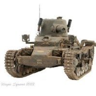
THEscaleSHOW Posted May 13, 2022 Share Posted May 13, 2022 On 04/04/2022 at 23:38, diablo rsv said: I can't say I was looking forwards to putting the tracks together, but then who does? As tracks go though, these weren't too bad. Just four sprues. Once the parts were removed and cleaned up the provided assembly jig was used to make up a six link section of track. First the inner part of the link is laid face down onto the jig. These are then held in place with the top half of the jig. The next part was a little fiddly. The end plates and pins, still on their section of sprue, have to be held in the correct position.... whilst a clamp is fitted to hold them in place. Once both sides have been clamped in, the top half of the jig can be removed. Using a small amount of adhesive the top half of each track link can be fixed. The problem here was that pins were forcing the halves apart so each one needed to be held until the glue had dried. This was going to slow the process down considerably so I found it best to use super glue. Unfortunately I only had the slow type available so it still took a little longer than I had hoped. Once I was happy that the glue was dry the jig could be removed. The sprue holding the pins in place could be cut off either before or after removing the jig. I chose to do it after just in case the halves came apart. There are no spare end plate/ pins so I was paranoid about losing one. I adapted the bottom section of one of the jigs so that it could be used to join the sections of track together. The tracks were then test fitted to the model. The idlers are fitted to a concentric cam so that the track tension can be adjusted. I'm not sure how many links the actual tank used but Ryefield call for 83 in the instructions. This seemed a little tight to me. Because of the working suspension I found that the front road wheel was getting pulled up by the track slightly. I added another link but to get the track tight the idler had to be adjusted back to its maximum and it still pulled up the front wheel but not as bad. I'm wondering if the springs in the suspension may be a little weak. Adding a little weight to the model seems to solve the problem but then I don't know if the model is sitting at the correct height. Once construction of the model is finished I will see if I need to add some permanent weight. Working suspension maybe a nice idea for diorama builders but I'm not so sure it's really necessary. As for the tracks themselves, I think they look pretty good, maybe some metal ones would add the weight needed to get the correct the sit of the model but I really don't want to go down the after market route on this build. Assembly wise Ryefield's system seemed to work well enough. Having no experience of building Shermans before I don't have anything to compare theirs to so it will be interesting to see in the other build's in the group how other manufacturers go about it. One thing that I did find invaluable was a decent pair of single sided sprue cutters, especially when it came to removing the sprue from the teeth on the endplates. Trying to clean those up afterwards would have been a pain but I find these cutters make such a clean cut that I didn't have to. That's the most tedious part of the build out of the way. Hopefully the upper hull and turret will go together fairly quickly. Wayne Can only agree with Ed-very nice and clean👍 MD 1 Link to comment Share on other sites More sharing options...
Ray_W Posted May 13, 2022 Share Posted May 13, 2022 My turn to join in and follow this build. Keep the detail flowing. It has been wonderful so far. I can't wait to start my RFM Firefly. Hopefully in this life. Ray 1 Link to comment Share on other sites More sharing options...
diablo rsv Posted May 24, 2022 Author Share Posted May 24, 2022 Finally I've managed to find a bit of time to post an update. Using Matt's @Cerberus advice above, I sorted out the seam line on the bogies, and you're right Matt, it was so much easier than trying to use stretched sprue, what was I thinking? They could probably do with a little cleaning up but I imagine once the weathering is applied little will be seen. You can also see the three vertical bolt holes that needed to be drilled out as RFM hadn't included them. I also followed the advice given by @Retired Bob and glued the front bogies to stop the track pulling up the front wheels. The upper hull went together without any problems. The only addition was where the front fenders had been removed, on the particular tank that I am modelling they seem to have left an extra piece of the fender so I added these with some plastic card. The turret also goes together without any dramas apart from the stowage bin. The way RFM have engineered it means that there are some difficult seams to remove. I found it easier to replace the moulded on band with one made from lead foil. RFM have included many optional parts in this kit and there is no indication of what part is needed for any particular subject so you really need to do some research into the vehicle you are modelling. However the one part that I could really have done with having options for is the radio box that was fitted to the rear of the turret on the Firefly. There seems to be at least two versions used, one has round access covers on the top of the box and the other one has square covers and this is the only one RFM have included. The construction of the boxes seems to differ as well. The included box has a welded plate at the rear of each side of the box, the far more common box has flat sides that extend slightly beyond the back plate. In fact I have found it very difficult to find images of tanks with the box configuration that RFM have included. It's a bit of a shame really as it is quite a prominent feature. It would be a fairly straight forward modification but I am running out of time with this project so I shall leave as is. Apart from some tidying up I think I'm finally there with the construction phase. Most Firefly images show them with plenty of stowage and this is something I would like to replicate. I need to do a little research as to what they would most likely have under those tarpaulins, I imagine most of it would be camo nets, spares, fuel and liberated items. With a bit of luck I can get the painting process started soon but the way things are at the moment I feel I may struggle to get this finished by the deadline. Wayne 19 Link to comment Share on other sites More sharing options...
PlaStix Posted May 25, 2022 Share Posted May 25, 2022 Hi Wayne. I am really pleased your project is still in progress and I have to say, I am very impressed with your attention to all the details. Lovely job and I really hope you get chance to finish your build in time. Kind regards, Stix 1 Link to comment Share on other sites More sharing options...
edjbartos Posted May 25, 2022 Share Posted May 25, 2022 That looks very nice Wayne, this will look amazing when painted... Ed 1 Link to comment Share on other sites More sharing options...
Bullbasket Posted May 25, 2022 Share Posted May 25, 2022 Hi Wayne. Lovely job on the Vc. I've no experience at all of Ryefield kits. What's your opinion of it? John. 1 Link to comment Share on other sites More sharing options...
Ray_W Posted May 25, 2022 Share Posted May 25, 2022 15 hours ago, diablo rsv said: RFM have included many optional parts in this kit and there is no indication of what part is needed for any particular subject so you really need to do some research into the vehicle you are modelling. Hi Wayne, Very neat. looking forward to some paint. A useful build for me. Watching yours come together has given me even more enthusiasm to start to my RFM Firefly. I know what you mean about the instructions. Similar experience with my RFM M4A3E8 in this GB. I made specific comment about wishing they would give more information when they provide a raft of options without explanation. I found myself diving for references and, as I am not a Sherman expert, this tended to be what I could dig up on the internet. I thought not a kit for the casual model builder. Having said that, I am really enjoying the experience. Even tracks and running gear, be they complicated. They go together very well once the instructions are deciphered. Hope you can meet the deadline. Ray 1 Link to comment Share on other sites More sharing options...
Retired Bob Posted May 25, 2022 Share Posted May 25, 2022 15 hours ago, diablo rsv said: Most Firefly images show them with plenty of stowage and this is something I would like to replicate. I need to do a little research as to what they would most likely have under those tarpaulins, I imagine most of it would be camo nets, spares, fuel and liberated items. Hi Wayne, your Firefly is looking very good, the problem with building just about any M4 is the plethora of different parts used by different companies that built the different sub-types. The Firefly counterweight/radio box on the turret rear is usually difficult to get photos of the type of top cover, Tasca/Asuka supply a couple of different types if you are lucky enough to have the information as to which to use. The stowage on the back would include the crew's personal kit, immediate use spares like road wheels and track links plus the tarps to keep their kit dry and to be used when they put up a night time weather shelter. No spare fuel or ammo would be on the outside of the tank because of the fire/explosive risks from shrapnel of a close miss. As I'm away from home at the moment I'm not getting any modelling done but reading 'Brothers in arms' by James Holland, its the D-day and beyond exploits of the Sherwood Rangers that used various types of M4 Sherman tanks. Very useful information about the wartime use of tanks but very little detail about the camouflage or differences of M4 variations, it's only when they mention things like "starting the twin diesel engines (M4A2/Mk.III) or the multibank Chrysler engine (M4A4/Mk.V) that you can work out what Sherman tank they are operating. 1 Link to comment Share on other sites More sharing options...
diablo rsv Posted May 26, 2022 Author Share Posted May 26, 2022 On 08/05/2022 at 19:06, Bertie Psmith said: Those tracks are identical to the MiniArt M3 tracks except MiniArt don't give you that jig. Was it really a help or a hindrance? Definitely a help Bertie, once you get into the rhythm it's not a bad system. I wonder if the jig could be used for the Miniart Grant. On 25/05/2022 at 08:25, PlaStix said: Hi Wayne. I am really pleased your project is still in progress and I have to say, I am very impressed with your attention to all the details. Lovely job and I really hope you get chance to finish your build in time. Kind regards, Stix Thanks Stix, to be fair RFM have most of the detail included, it's just my OCD that won't let me ignore the odd missing detail. On 25/05/2022 at 11:39, Bullbasket said: Hi Wayne. Lovely job on the Vc. I've no experience at all of Ryefield kits. What's your opinion of it? John. Nice to see you back John. This my first of theirs and I am really impressed with the level of detail. The plastic feels similar to that of Takom but with much finer attachment points between the parts and sprue. My only gripe is that they include so many optional parts without any indication as to which is needed for a given subject. I have their Challenger 2 in the pile and this kit has given me an urge to get started on it. I just need to clear the backlog of started kits first. On 25/05/2022 at 14:36, Retired Bob said: Hi Wayne, your Firefly is looking very good, the problem with building just about any M4 is the plethora of different parts used by different companies that built the different sub-types. The Firefly counterweight/radio box on the turret rear is usually difficult to get photos of the type of top cover, Tasca/Asuka supply a couple of different types if you are lucky enough to have the information as to which to use. The stowage on the back would include the crew's personal kit, immediate use spares like road wheels and track links plus the tarps to keep their kit dry and to be used when they put up a night time weather shelter. No spare fuel or ammo would be on the outside of the tank because of the fire/explosive risks from shrapnel of a close miss. As I'm away from home at the moment I'm not getting any modelling done but reading 'Brothers in arms' by James Holland, its the D-day and beyond exploits of the Sherwood Rangers that used various types of M4 Sherman tanks. Very useful information about the wartime use of tanks but very little detail about the camouflage or differences of M4 variations, it's only when they mention things like "starting the twin diesel engines (M4A2/Mk.III) or the multibank Chrysler engine (M4A4/Mk.V) that you can work out what Sherman tank they are operating. Thanks Bob, Would I be right in thinking that they would be carrying different stowage depending whether they are on the move or going into battle? The photo of my subject does seem to have a Jerry can stowed on the glacis, but it has just come off of the landing craft. Of course that could just contain water. Wayne 1 1 Link to comment Share on other sites More sharing options...
Bertie McBoatface Posted May 26, 2022 Share Posted May 26, 2022 33 minutes ago, diablo rsv said: I wonder if the jig could be used for the Miniart Grant. I would keep it safe just in case you are ever tempted to do one. 1 Link to comment Share on other sites More sharing options...
Retired Bob Posted May 27, 2022 Share Posted May 27, 2022 13 hours ago, diablo rsv said: Would I be right in thinking that they would be carrying different stowage depending whether they are on the move or going into battle? The photo of my subject does seem to have a Jerry can stowed on the glacis, but it has just come off of the landing craft. Of course that could just contain water. Reading the books about the tank fighting in Normandy, they usually pulled back to a safe area each evening as it got dark to re-fuel and re-arm, carry out any urgent maintenance, that left a few hours to grab some food and a couple of hours of sleep. Their day to day kit was stowed on the tank ready for whatever came the next day, usually starting at 0400 hours, long days of high stress with very little sleep and the ever present danger of snipers meant the life expectancy of a tank commander was on average 2 weeks! Jerry cans on a tank would be for water, tea with condensed milk was drank, the water was heated on fire made by mixing petrol with soil to make the fuel. When the tank had it's hatches locked down in a combat area, a 75mm shell casing was their toilet. Next time you are having a bad day, remember, things could be worse. 4 Link to comment Share on other sites More sharing options...
Jasper dog Posted May 29, 2022 Share Posted May 29, 2022 Super clean build Wayne, be great to see it painted! Good luck getting all your stowage together, a simple solution could be getting the general shape together and cover with a tarp before tying down. Atb Darryl 1 Link to comment Share on other sites More sharing options...
diablo rsv Posted June 2, 2022 Author Share Posted June 2, 2022 On 29/05/2022 at 20:46, Jasper dog said: a simple solution could be getting the general shape together and cover with a tarp before tying down. Thanks Darryl, That's pretty much what I have in mind. I was going to add the stowage before painting but as time is against me it's more likely that I will get on with the painting and add stowage another time. On 27/05/2022 at 11:30, Retired Bob said: the life expectancy of a tank commander was on average 2 weeks! That's horrific. Wayne Link to comment Share on other sites More sharing options...
Retired Bob Posted June 2, 2022 Share Posted June 2, 2022 3 hours ago, diablo rsv said: That's horrific. I'm still reading 'Brothers in Arms'. Having completed the first month of fighting in Normandy since D-Day the Sherwood Foresters had lost 88 tank crewmen killed or severely wounded, 40 of these were tank commanders! Link to comment Share on other sites More sharing options...
diablo rsv Posted June 19, 2022 Author Share Posted June 19, 2022 Unfortunately I just haven't found the time to get this build finished by the deadline. Is it possible to get this thread be moved to the AFV wip section @PlaStix? Link to comment Share on other sites More sharing options...
PlaStix Posted June 21, 2022 Share Posted June 21, 2022 Hi @diablo rsv As you will see, I have moved your thread. I've left a link in the STGB threads, which will remain active for 30 days. Thank you for taking part in the GB. It was looking excellent last time seen! Kind regards, Stix 1 Link to comment Share on other sites More sharing options...
Kingsman Posted June 21, 2022 Share Posted June 21, 2022 (edited) On 3/29/2022 at 9:37 PM, diablo rsv said: For the drive sprocket I went with the fancier Chrysler one ( part numbers 3/9 ) as this seems most common on the VC. This was the only type of sprocket ring ever factory fitted to M4A4, M4A6, M4(105), M4A3(105), about 85% of M4 Composite, about 85% of M4A3(76) and all M4A3E8. All built by Chrysler. The balance of M4 Composite and M4A3 were built by ALCO and Fisher respectively. As for the track tensioning, 2 points to note for the future. First, forget the workable gimmick. Replace the springs with solid plastic 3mm bar, sprue or similar and glue the swing arm pivots. That will stop them being pulled up front and back. Second, you need to use the idlers as on the real thing to tension the tracks. Don't glue them until you fit the tracks so that you can adjust the fit, The idlers were on an eccentric axle which rotated upwards and rearwards with the big nut on the inside end of the idler bracket. So the height of the idler actually varied and there could be a slope between idler and rear bogie. Regarding markings, yes Guards Armoured Div had Firefly VCs. At the time of Op Market Garden. Coldstream Gds had M4 Sherman I and IC, Grenadier and Irish Gds had M4A4 Sherman V and VC. Arm of Service marking 51 for Grenadiers, 52 for Coldstream and 53 for Irish. So the kit GAD markings would seem to be correct. One other thing to note is that side and front white stars were banned on British tanks before D Day. The only star you should see in NW Europe is a star-in-circle on the engine deck (usually) or turret top (sometimes). Edited June 21, 2022 by Das Abteilung addition 1 1 Link to comment Share on other sites More sharing options...
diablo rsv Posted October 25, 2022 Author Share Posted October 25, 2022 So after what seems to be a long hiatus I have decided that it was about time I tried to regain my model making mojo. I have had a couple of small attempts to get back into it but all of my current projects have either been giving me grief or reached a particularly boring point in the build process. With the Firefly I just couldn't decide on how I wanted the finished model to look, stowage, wading gear, weathering, markings, paint finish etc. In the end I decided to add stowage as there are plenty of photos of Fireflies heavily laden. I toyed with the idea of making my own but laziness took hold and I bought a set from Black Dog that has been designed for the Firefly. It needed some modification to get it to fit and I bedded it in with some tarps made from Greenstuff putty. A camouflage net was made from old plasterers scrim ( the straps are temporary ) and the spare tracks are from Bronco. I had a go at making a spare track link rack for the right hand side of the turret but couldn't find a clear reference for one so it's my best guess. Straps and tie downs will be added after painting. I think I have added enough to make it look interesting and not gone over the top with it. Finally, apart from a couple of small details, I have finished with the build stage. The model was then striped down and cleaned ready for some Mr Hobby 1500 black primer. This will probably be how it remains for a while as I really want to take part in the Armoured Cars and Halftracks Group Build. I must say it's nice to get back into it and even though I have popped into the forums occasionally I feel I have missed out on some excellent work. Hopefully in the next couple of weeks I can catch up with what has been going on. Wayne 8 Link to comment Share on other sites More sharing options...

Recommended Posts
Create an account or sign in to comment
You need to be a member in order to leave a comment
Create an account
Sign up for a new account in our community. It's easy!
Register a new accountSign in
Already have an account? Sign in here.
Sign In Now