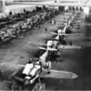
109 fan Posted February 22, 2022 Share Posted February 22, 2022 Here is my current project. I have been working on it (them) for some weeks but have not posted it here until now. Since it has appeared on the 72nd Scale Aircraft site, I will combine some of those posts on this thread. Please forgive the somewhat disjointed nature. This is my second foray into 1/72 Gigants. The first was finished three years ago and can be found on this site. CE6CF801-8B93-4102-A27A-0A6D8D3359E8_1_201_a by Barry Numerick, on Flickr It looks like the mythical elephant's graveyard from an old Tarzan movie, but it is simply an experiment. I'm trying to find an Italeri Me 323 with a non-warped forward fuselage and clam shell nose. Since I have 15 of these kits I should be able to find one that is reasonably close but some of them are rather bad. My original build from a few years ago was a challenge in this area but was eventually closed up with 5 minute epoxy and epoxy putty. This will probably be an intermittent, long term project. The intention is for a 6 engine D-1 version in the midst of repairs. One fuselage side had large areas of red primer and the left forward wheel covers were removed exposing the complex gear structure. Here is another shot. BTW, I am a sucker for this kit. Most of them were bought at shows for $25 or less; cheaper than many 1/72 scale fighters. 0ADC0ECC-C238-4B2A-B2CE-07F1B341BCBB by Barry Numerick, on Flickr I found a Life Magazine color photo on the web of an AAF officer examining an abandoned Me 323 wreck in the Med. A piece of the fuselage fabric was torn and folded back showing the red primer interior of the fabric. With the help of my wife (since I am somewhat red/green color blind - thank God the Germans painted by numbers!) we picked an appropriate Gunze red shade. I began by spraying the interior tubular frame with RLM 02 Grey. Then thin strips of Tamiya tape were cut and applied over them and red was sprayed on the interior. I am not overly concerned with precision here. With the nose doors closed the interior will only be visible through the small fuselage windows. I want to only give the impression of the interior structure. I started another Giant some time ago and sanded off all of the interior framework with the intention of scratch building it from plastic and aluminum tubing. That one will be down the road. C7CEC1DF-DBC9-4DE2-A402-4088DEEBB964_1_201_a by Barry Numerick, on Flickr 1B152FB0-AE9E-43F8-B3D8-5B591ED8C736_1_201_a by Barry Numerick, on Flickr Next will come the interior windows and adding Plastruct plastic rod sections directly behind them to represent the framework in those areas. It would not have been possible for the kit windows to indicate this. Then on to the cockpit and wing engineer's stations. I will not batch-build Gigants...I will not batch-build Gigants... I will not... 0899BEC8-88DB-4F6B-B252-745B7F89D910_1_201_a by Barry Numerick, on Flickr Honest! Here's what's going on. Have you ever built some sub-assembly and thought "I can do that better?". That happened here. It was time to begin gluing in the windows. One the last Me 323 (yes, Bert, I finished one a couple of years ago. The build is on these pages), I didn't alter the windows at all. They are wavy, typical mid-1970's clear part technology. Since originals were just acrylic (tor cellophane?) sheets sewn onto the fabric fuselage sides, I thought they could be rippled. But the windows on the Me 323 are larger than the Me 321. Something had to be done. Sooo, I sanded them through 1200 and 1500 grit sand paper; then 6000, 8000 & 12000 micro-mesh, followed by Novus scratch remover and finally Dawn dish washing detergent. There are 22 of them. That took some time. They were then tacked in with diluted white glue on the inside followed by a filling application of 5-minute epoxy on the exterior. Before setting up the excess was wiped away with a Q-tip moistened with denatured alcohol. This step can be repeated until any gaps are gone. Another application or two will be required There are two trapezoidal windows at the bottom of each clamshell door.These kit parts did not fit well so I cut some clear plastic (butyrate?) to fit. This looked much better and no polishing was required. Again, the wheels started turning and I thought - why not make all of the windows from this stuff. I have a Ju 52 that has resided on the shelf of doom for over 20 years. All of those windows were replaced with this clear plastic and I was very pleased with the result. Time to paint another fuselage or two and experiment. No, I will not finish them all simultaneously. But hope springs eternal. Tonight I finished painting and masking the support structure and sprayed on Gunze H-47 red brown. This is the unholy mass of Tamiya tape strips after removal. 147C57D2-E4C8-41FE-937E-E0D2EC5B328C_1_201_a by Barry Numerick, on Flickr And here is a look behind the curtain showing bits of Evergreen rod representing the support structure behind the windows. These are only intended to give the impression of the framework. Once the airframe is completed everything goes dark and little can be seen of the interior. C328C956-F2EC-42F4-8E49-A8A19823AC48_1_201_a by Barry Numerick, on Flickr And this is the view from the inside. 6B6430D0-5CB9-4463-81BB-6488FEE26603_1_201_a by Barry Numerick, on Flickr Masking the windows on the outside before painting will tidy up the edges. Now that is better. For the past few years whenever I build a model, I build two of them. It started with the Special Hobby 109 E, then a double build of the Tamiya and AZ 109 E's, and now the Gigant. I don't expect to complete both of them simultaneously but I do take the better of the two builds and forge ahead with that one. The other will be a "running start" for another project down the road (I hate the term "shelf of doom"). After thinking I could do better than the sanded and polished kit fuselage windows, I decided to cut each one of them individually from clear sheet plastic. This was time consuming, to say the least, but the result was very satisfying. I used an old sheet of .030" clear that was bought at the local hobby shop years ago. I have no idea what it is but it has a blue protective film that is peeled off before final shaping. The pieces were cut with a "Chopper" then beveled on all four sides using 1200 grit sandpaper. The beveled edges face outward which left a very small channel. They were initially tacked in using diluted carpenter's glue, which is quite a bit stronger than typical white glue. It must be cleaned off with a Q-tip since the excess does not disappear like white glue. The channel will (hopefully) provide a very small trough for 5 minute epoxy to make a bond on the outer surface. Again, I apply it with a toothpick and quickly wipe off the excess with a Q-tip dampened with denatured alcohol. The plastic is very clear and resulted in a great improvement over the kit parts. After two days of custom fitting all of the side windows are in place as well as the tubular framework behind them. Here is where things stand at the moment. 9D60ADDE-2CAC-4311-9FD8-7EE338DC36C8_1_201_a by Barry Numerick, on Flickr 86B008FE-851A-4BDF-B1AB-3194B8978F2C_1_201_a by Barry Numerick, on Flickr FE492204-BB10-44F5-9F03-52AA8937F371_1_201_a by Barry Numerick, on Flickr I'm progressing toward gluing together the first two fuselages. The floors were painted Tamiya Buff then streaked with raw umber oil paint. Lots of tabs were glued to the fuselage sides to provide strength, much like a vac form kit. The fit varies from one kit to the next, mostly due to warpage of the large parts. I've removed all but one of the locating pins on the lighter grey kit to more easily match the fit of the nose clamshell doors. DA2D5D7B-F84D-46D3-8ABE-6EAC12DAD86E_1_201_a by Barry Numerick, on Flickr D8113737-2B03-43B1-96ED-1C2470A10AC3_1_201_a by Barry Numerick, on Flickr A friend recently gave be some plastic tape that has quite a bit of stretch to it. I immediately thought of this use for it. Since the 45 year old parts have varying degrees of warpage, this tape was invaluable in manhandling the nose together. These two look like they came out second best in a bar fight. But the tape worked better than any other technique that I could have imagined. Two fuselages are now glued together and I am moving to the tail surfaces. Having build one of these beasts daily recently is a big help. I know where the pitfalls are and what shortcuts to take. 50DE61DA-7D87-4A82-88AD-D39FFC3EE01D_1_201_a by Barry Numerick, on Flickr There is a reason why there are so many of these on the table. Case in point is the stab/elevator joint. On the first two examples I filed a groove in the back of the stab using a round file. On the third attempt I just sanded the mating surface of the stab at an angle, allowing the elevator to be attached more easily and tightly. Here you can see the amount of sanding necessary. Remnants of Gunze Mr. Surfacer 500 can be seen on the grey elevators. They were sanded to within an inch of their lives. 95D4A0D5-D4BA-4A34-B8FB-E01F7DF230B0_1_201_a by Barry Numerick, on Flickr The bottom of the fuselage is a terrible fit. The long fuselage halves are often warped in multiple directions. I tried epoxy putty, but it was a bear to sand flat and required remedial work wit Mr. Surfacer. Ray Rimmel built this kit as a review model in a 1977 issue of Scale Models magazine. And yes, I bought it at the news stand, not from some dusty shelf of very old mags. He recommended scribing a piece of .005" plastic card to represent stringers and attaching it to the top and bottom of the fuselage. Simple enough, but how do you stick it on? Liquid glue would melt this stuff so I made a mock up and began to experiment using a sheet of .040" plastic sheet as a fuselage stand-in. On the first attempt I used carpenter's glue. This stuff dries hard and will not harm plastic. No joy. The scribed sheet wants to curl up so the glue has to set rather quickly. Then I decided to use my favorite glue for this beast - five minute epoxy. I mixed up a large puddle of the stuff and troweled it on the the fuselage. Then I squeezed out the excess and wiped the edges with denatured alcohol moistened Q-tips. It set up very nicely. So now I 've overcome my fear of thin plastic sheet cladding. This is the first attempt using carpenter's glue a .040 sheet of plastic as the base. 85D2CD0D-8969-4496-9E30-C64D7A229082_1_201_a by Barry Numerick, on Flickr Then the real deal using 5-minute epoxy. I've tried to darken these photos and increase the contrast to highlight the ribbing. Not really successfully. E499161C-DF41-4772-82D5-69743A195B2D_1_201_a by Barry Numerick, on Flickr 688C9D23-9B5C-4B82-BB06-5D2137A86443_1_201_a by Barry 688C9D23-9B5C-4B82-BB06-5D2137A86443_1_201_a by Barry Numerick, on Flickr, on Flickr That's enough for now. Work has been done on the flight engineer's stations in the wing. More of that tomorrow. Thanks for following along! 18 Link to comment Share on other sites More sharing options...
neil5208 Posted February 22, 2022 Share Posted February 22, 2022 Impressive work and intimidating size Link to comment Share on other sites More sharing options...
RidgeRunner Posted February 22, 2022 Share Posted February 22, 2022 Nice work and an interesting subject, Barry Martin Link to comment Share on other sites More sharing options...
AdrianMF Posted February 22, 2022 Share Posted February 22, 2022 Madness! But epic at the same time. Very neat work and ingenious solutions too. Regards, Adrian 1 Link to comment Share on other sites More sharing options...
109 fan Posted February 23, 2022 Author Share Posted February 23, 2022 Thank you, gentlemen. The next items for attention will be the cockpit and wing. I have found quite a few photos of the cockpit, radio operator's station and the flight engineer's stations in the wings. The issue is that almost all of has to be scratch built. I had initially wanted to open only one of the engineer's stations, but since both have to be built why not open them both? First up is the cockpit. What is presented in the kit is mostly wrong, just two seats, control sticks and nubs for rudder pedals. There is also a decal instrument panel. The positioning is wrong so I started by adding sheet plastic to the floor. The seats have an interesting configuration. Half of the seat back is on a rear bulkhead and the other half is on a door that opens to the radio operator's compartment. These were made from Evergreen half-round stock. B8451DFB-4C29-4A99-BFC7-4629C0B86B7F_1_201_a by Barry Numerick, on Flickr There is much more to be done here but I decided to move on to the engineer's compartments. These are located between the inboard engines on both wings. The kit only has two small windows and a separate hatch, and these will not be used. First to be made were the side panels. I started by splitting the airfoil shape and making templates by trial and error. Then a complete sidewall was made with more cutting and fitting. These shapes have an interlocking structure with edges which presented issues. I tried making the edge with square .020" plastic, but they wouldn't keep their shape. Then I went to an old favorite, thin lead wire, in this case .015" diameter. I bent the wire around the outside of the plastic, then used the outside edge of a Tamiya tape dispenser to roll them flat. They were then glued on with Tamiya Extra-Thin quick setting glue. After that came stiffening ribs of .010" x .020" Evergreen strips. There will be a lot of gizmology here and unfortunately it will be impossible to see once buried in the wing. Here's where they stand tonight, along with the lead wire and Tamiya tape "tool". 5A9E4699-307C-4ADF-9987-F2ECAB6BC35B by Barry Numerick, on Flickr FEDA5A0B-4C38-4CD3-8E43-617BC74D215D_1_201_a by Barry Numerick, on Flickr To clarify, this is the exterior of the station on the upper surface of the wing. me323_11 by Barry Numerick, on Flickr Moving along with the flight engineer's stations. This amounts to scratchbuilding two additional cockpits. The first photo shows the basic form before paint. I did end up using very thin superglue to permanently fix the solder pieces to the sidewalls. The thick plastic rods are the beginnings of the wing spar structure. I will only make these for the areas where they can be seen, like behind these stations and at the rear of the cockpit. 408DA3E2-CA9C-4BF2-B93D-1D840CF06302_1_201_a by Barry Numerick, on Flickr From here the visible areas of the wing interior were painted red and the station interiors RLM 02. I used a raw umber watercolor wash and dry brushed with oils. Much of the interior detail is pure gizmology since there are very few photos of these ares. The black half-round panels have many yellow switches. I tried a number of alternatives, but decided to take the easy route. I took some lead foil and heavily embossed it with a riveting tool. This was then cut into thin strips and glued (again) to the Evergreen half-round stock with Tamiya Extra-thin. The whole thing was sprayed black and attached to the sidewalls. Then I gently rubbed a yellow Prismacolor pencil along the raised pips. Close enough for a 1/72 scale panel in the dark interior of a wing. Some clear decal paper was also sprayed black and cut into thin strips. These were cut into small squares and some lettering was simulated with a silver Prismacolor pencil. The instrument panels came from a He 111 Zwilling Eduard photo-etch sheet that I ordered specifically for this project. The seats have been made and are almost ready for installation. Then some cross members will be added to the spar structure and I can finally close up this wing. 2AD4F4C4-B5E2-409F-9869-6BF8D7F1389C_1_201_a by Barry Numerick, on Flickr 7FAAB8B9-345E-477B-9E53-35480755E81E_1_201_a by Barry Numerick, on Flickr 44C2A651-BE68-4ED0-A41E-65D1D826A6F1_1_201_a by Barry Numerick, on Flickr B2973BC1-EE13-4778-9B6A-149E9C7811FB_1_201_a by Barry Numerick, on Flickr 1A2854E9-348B-429D-AB45-EAAB58117E66_1_201_a by Barry Numerick, on Flickr 6 1 Link to comment Share on other sites More sharing options...
stevehnz Posted February 23, 2022 Share Posted February 23, 2022 Cripes Barry, this is beyond impressive, in a delightfully potty sort of way. I'm full of admiration for you though & will be keen to see how these progress. After years of lusting after just one of these kit, when GWH brought out their 1/144 version, I bottled on the big un & went smaller. A very nice looking kit in the box it is too. Nevertheless, these still fascinate so I'll hang around a bit. The whole concept of the 323 & the bravery of those who crewed them fills me with awe. Steve. Link to comment Share on other sites More sharing options...
109 fan Posted February 23, 2022 Author Share Posted February 23, 2022 Thank you, Steve. I'm not sure this plane had a potty; will have to check my cutaways again 😁. I have both the GWH D and E kits and you are right; they are very impressive. I would love to see a 1/72 Gigant done with the sophistication of modern tooling. In the meantime, we just hone our scratchbuilding skills. HPH have been working on their 1/32 Gigant for years. In fact I've used some of the published photos on the sub-components as references for this build. Now that one will be impressive. 1 Link to comment Share on other sites More sharing options...
109 fan Posted March 6, 2022 Author Share Posted March 6, 2022 I have finished the engineers' stations. Curiously, I can't find and evidence of seat belts on either these seats or the radio operator's. Also, the pilot & co-pilot seats only seem to have lap belts, no shoulder harnesses. The corrugated stops are walkways to reach the stations from the fuselage. They were made from Evergreen grooved siding. Here is where things stand at the moment. This is the left station: A017D862-8912-443C-9116-432C28402019_1_201_a by Barry Numerick, on Flickr 666A3EA2-4B9F-498A-A12A-25ABB38DC7CD_1_201_a by Barry Numerick, on Flickr And the right: A017D862-8912-443C-9116-432C28402019_1_201_a by Barry Numerick, on Flickr 762031DC-DC80-4968-B122-AD6185F6FF54_1_201_a by Barry Numerick, on Flickr I'm relieved that this bit of scratchbuilding is over. Now on to framing and installing the windows on the upper half of the wing and building the hatch. The upper wing is warped so it will be a challenge. Some framing may have to take place after the wing halves are joined. 6 Link to comment Share on other sites More sharing options...
109 fan Posted March 14, 2022 Author Share Posted March 14, 2022 A bit more progress to report tonight. I've been working on the upper wing in hopes of getting the center section glued together soon. The top section of the engineer's station had to be boxed in. This presented its own set of issues, again related to warpage. If the upper hatches were to be closed this wouldn't matter, but the wing is warped right in that area making one side of the hatch higher than the other. Fortunately, I have collected a number of these kits. After making some progress before discovering the warpage problem, I moved on to a straighter wing. Here is the beginning of the framing process. The sides were made from .030" square Evergreen strip. IMG_8342 by Barry Numerick, on Flickr In this photo the framing is nearly complete and primed with Mr. Surfacer. IMG_8350 by Barry Numerick, on Flickr Finally, a few more bits were added and the section was painted inside and out with RLM 02. IMG_8354 by Barry Numerick, on Flickr It is a little disheartening how little of the scratchbuilt stations will be seen through these hatches. IMG_8355 by Barry Numerick, on Flickr IMG_8356 by Barry Numerick, on Flickr 4 Link to comment Share on other sites More sharing options...

Recommended Posts
Create an account or sign in to comment
You need to be a member in order to leave a comment
Create an account
Sign up for a new account in our community. It's easy!
Register a new accountSign in
Already have an account? Sign in here.
Sign In Now