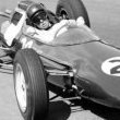
Malc2 Posted September 24, 2021 Share Posted September 24, 2021 (edited) So while the 006 was in hospital being attended to, the reserve model came to the fore. I always liked the March team cars and am a fan of Adrian Newey, so the March 881 was a must have as it was his first F1 design. I found a very well thumbed (OK tatty) copy of How To Build a Car in the library and read it pretty quickly, it was a fascinating read. I also found great references to the 881 in the Japanese F1 Modeling mags Vol27 and Vol28 which between them have 37 pages of photos comparing chassis 881/1 and 881/3 in detail, copies of which I had squirreled away some years ago for just such an occasion as this. I have seen a couple of builds of the S27 kit and it is very apparent that there is something wrong with the nose in a Pinocchio telling lies kind of way. Have a look at this pic taken at Monaco (it has the alternative T shape air intake). Below is an OOB S27 build – photo credit wixy500, slightly different angle, but compare the position of the rear of the front wing end plates. I couldn’t find any reliable drawings of the 881 but I found the wheel base and track on Wiki and drew them out to 1/20. The kit matched the wheel base exactly, so leaving the front tyres in position, I moved the body and nose back until the wing end plates looked right, the result showed that 8mm(!) needs removing. Body moved back to put the nose where the end plates look about right in relation to the front tyres After giving the body several coats of looking at, I figured the best place to make the cut was just in front of the undertray where the taper along the top of the nose is at its shallowest. The sharp edge along the upper side of the nose should be rounded off - compare to the Monaco photo above So I broke out the brave pills, popped out to the workshop and cut the nose off - gulp! I used the cross slide to keep the cuts parallel The cuts were nice and even and just needed a quick swipe with the sanding block to smooth them off. Back in the model room I compared the results with my drawing and it all looked good. Side view So I super glued the nose back on and filled the step with Milliput, most of which will be sanded off to restore the curve. New suspension positions were marked on before the cut was made by simply measuring 8mm back from the originals. Now I had to wait for a couple of days to let it really harden off. All sanded down, with the nose cone bluetacked in place Air intake/roll hoop also in place Back on the graph paper with the camera held further away reducing the barrelling effect. Side view Looks much more in proportion to me With front suspension on, it may need the top push rod location moving back a small amount to the rear of the eyebrow fairing, which needs extending backwards too, looks like the top wishbone rear attachment point should be further forward too, I will have to see what the effect on the hub end this would make Top pushrod location moved backwards, compared to photo looks about right, also compare the new lower rear suspension pickup point in relation to the gear change bulge, now looks about right too. Obvs I'm slightly ahead of this, but will update more tomoz if your nose is pressed to the screen and wanting to see how it all turns out. Malc. Edited September 24, 2021 by Malc2 9 Link to comment Share on other sites More sharing options...
Bengalensis Posted September 25, 2021 Share Posted September 25, 2021 Another resin challange, good to see! 👍 The late 80s to early 90s saw many lovely looking F1 designs, and some of the very best of course carry the name of Adrian Newey. Link to comment Share on other sites More sharing options...
Malc2 Posted September 25, 2021 Author Share Posted September 25, 2021 (edited) Thanks @Bengalensis! Yes the clean aero look of this era of cars and the simple colour schemes also make it my favourite period. Also the sound was amazing. OK, so lets get caught up some more. Trans case, all the sloppy fit tabs have been cut off the suspension arms and the gaps filled for the lower wishbone and driveshafts Another issue to fix is the gaping hole behind the seat No problem a wodge of plod can’t solve, it will need another go to fill the remaining imperfections The gear change bulge was almost circular, but should be teardrop shape. So a small bit of Milliput superfine left over from a ceramic repair (no I didn’t drop it) was used to elongate it and some finessing of the rear to make it more teardrop shape has worked wonders. The eyebrows over the pushrods were also extended backwards, the pushrod location is a tiny bit low, but I am going to ignore that…. I may reduce the height of the eyebrow a bit when the filler is harder. I also sharpened up the crease line that runs horizontally about half way up the nose Looking at other builds on the net, I had a suspicion that the rear wing was too low, so I need to assemble the whole thing to see where we are. The supports should fit like this on the gearbox, there is a tab and slot on the inside face that locates the support on the gearbox With the trans assy in place, the body pushes them down. Which means they touch the under tray and hold the body off None of the others who built this kit mentioned finding this little problem! So some temporary wing mounts were made to fit round the body. All these do is allow the wing to be put in place to establish if its height is correct. Then I assembled the rear wing, the elements were somewhat flat. Making the rear edge higher than the top of the end plate So some judicious bending and all is better. The wing assembly in place, the line on the block is at 50mm which is about the correct height in 1/20 scale for the max wing height for 1988, and shows the wing is about 4mm too low New new mounts made, the small vertical feature is the locating tab I mentioned earlier that locates in the gearbox, the cross piece is to support the rain light. New position looks about right, excuse the slight sideways misalignment, the blue tack was sagging under the weight of the wing faster than I could take the picture Wing end plate now does not disappear behind the rear tyre and the top of the wing is about level with the top of the air intake as it should be. Hope it all makes sense! Comments welcome Malc. Edited September 25, 2021 by Malc2 8 Link to comment Share on other sites More sharing options...
Stickframe Posted September 30, 2021 Share Posted September 30, 2021 Hi Malc, Well, you got me hooked with a Studio 27 kit (which I like) and....cutting it up! very brave indeed! Looking forward to seeing this shape up! Too bad about the rear wing mounts - not the sort of thing a guy likes to discover in a build - nice fix tho. I've built a few models of F1 rear wings (PE and white metal), and always have troubles assembling them (wings to brackets) so much so, that I've taken to the miserable task of drilling through the PE and inserting small brass rivets to hold it all together! Why you might ask? If not pinned I will almost inevitably know the assembly apart somewhere along the way, usually post paint, when it actually matters! Looking forward to your next post - Cheers Nick 2 Link to comment Share on other sites More sharing options...
Malc2 Posted September 30, 2021 Author Share Posted September 30, 2021 (edited) Cheers Nick! I had always held S27 in high regard, then you have one and suddenly you find the master mould maker must have had a senior moment or something. Wait till you see how bad the S27 Tyrrell 019 I have is! I only found one other build of the S27 019 on a Japanese forum and he seems to have given up after chopping it to pieces..... Or maybe that was his intent🤣 However I have a solution😁 So time for another update. The next issue is that the undertray of the model comes to the outer edge of the body, on this car the body colour wraps under the monocoque. So to hide the join between the undertray and the body and make painting easier, I decided to rebate the undertray. Some 1.5mm square rod was bent and superglued to the lower edge of the body. The undertray was trimmed to suit and in place below. And the edges rounded off All through the above stuff, I had been wondering whether or not to remove the spurious side pieces on the rear body that don’t exist in race photos – the bits circled in red below, I think S27 added them to hide the lack of a Judd V8 engine. I have found only one picture that shows them, which is of an 881 in a museum, none of the period race pictures show them Not visible here My OCD got the better of me and I decided to cut them off, otherwise every time I looked at the model I know I would regret not removing them. So break out the razor saw of mass destruction. One gone Now there is a nice view of the resin forming the tub. To fill the gap there will be more exhaust and a couple of coolant pipes and lots of matt black paint. Lots still to do. As usual comments or criticism welcome! Malc. Edited September 30, 2021 by Malc2 5 Link to comment Share on other sites More sharing options...
Malc2 Posted October 5, 2021 Author Share Posted October 5, 2021 Evening plastic basherz, are you sitting comfortably? So lets begin. The seat was modified slightly to include the U shape for the drivers legs, which seems typical by the late 80’s, first a bit of plastic to define the shape. Lots of Milliput equals leg shape definition and new side consoles for the roll bar adjustment levers. Moving on… Springs and dampers were made that go either side of the gearbox, you can also see I made a bit of a mistake, past me had put the lower wishbone in upside down, and the tab I assumed filled the gap above (which I cut off) needs to fill the gap below in the gearbox slot, so I removed some of the card filler I added previously. This means the exhaust now does not foul the wishbone… Win! Having removed the fake sections of monocoque side, I need exhaust headers to fill the gap. While wondering the best way to make them, I suddenly remembered I had some suitable exhausts in Mine Schrottplatz, so I dug them out and while I was there found a complete V8 from a Jordan 191, hmmmm, why not use it? So exhausts were popped in some 99% Isopropanol to clean the paint off. Hacked the gearbox off the engine, glued the engine halves together and offered it up Wow perfect fit Its close enough to a Judd V8 considering only a tiny fraction of it will be visible in the finished model. Now I need to let the mad professor loose with the dremel to carve out some room for the engine. Engine placed over the soon to be resin dust From the side just because. Malc. 6 Link to comment Share on other sites More sharing options...
klubman01 Posted October 6, 2021 Share Posted October 6, 2021 Looking good! Love the way you adapted the engine to suit your needs. Good luck with the "hacking and filing"! Trevor Link to comment Share on other sites More sharing options...
Vesa Jussila Posted October 6, 2021 Share Posted October 6, 2021 Looks excellent. And this car is really beatiful. Link to comment Share on other sites More sharing options...
Kitkent Posted October 6, 2021 Share Posted October 6, 2021 This is good stuff! Ive never set eyes on a Studio 27 F1 kit personally but it doesn't seem that accurate! The rear end especially seems a bit off,the wing position is quite bad on its own. Interesting to follow along if that's ok! Chris. Link to comment Share on other sites More sharing options...
Malc2 Posted October 8, 2021 Author Share Posted October 8, 2021 @klubman01 Thanks, not too bad as it turns out! @Vesa Jussila Yes, I love the atmo cars of this period. @Kitkent Nothing a saw, glue and filler can't fix! Back in the garage with the hoover on maximum suck, let the grinding commence. The mad dremel professor handed back the body, he had almost gone through in only two places……. No matter, some white powder and superglue on the inside and all is well, The heat release from the catalytic reaction is significant as the glue sets, so be careful if you are doing this on an injection moulded part Also a minor repair on one corner of the radiator exit where the dremel tool tried to escape. Tape to form a dam Baking powder in place and a drop of superglue added 10 seconds later the tape can be removed to leave a smooth exterior surface, just needs squaring up. Sharp superglue edges are quite brittle, so fine sand paper is used for clean up to avoid chipping it off again. The powertrain in place looking like it belongs there…… And with the undertray - this is all you can see of the engine! Thanks for looking, Comments welcome! Malc. 7 Link to comment Share on other sites More sharing options...
Malc2 Posted October 15, 2021 Author Share Posted October 15, 2021 (edited) Evening Chaps, After 24 hours-ish, the exhausts were retrieved from the isopropanol which also had also conveniently separated at the glue joint. They had cleaned up well and were glued back together. To index the engine accurately and repeatably it was bedded in Milliput. The trans was pinned to the engine in a similar fashion to the Tyrrell 006. The moulded on exhausts were removed from the undertray New exhaust ends made up, the exhaust headers were shortened to tuck the exhaust closer to the engine sides. One last mod to the body was to add the small but distinctive flare to the rear body where it meets the undertray. 20thou plastic card scraps rebated in to the body, so the floor remains flush Card sanded to profile then filler added and smoothed with the wet end of a paintbrush handle I then dashed in to the paint booth (Garage) and threw some paint in the air and caught some of it on the body This side That side The underside Showing the extensions to hide the floor edges Backside Seat in primer – already with some remedial sanding. Comments Welcome! Cheers Malc. Edited October 15, 2021 by Malc2 6 Link to comment Share on other sites More sharing options...
Bengalensis Posted October 15, 2021 Share Posted October 15, 2021 Good progress! Link to comment Share on other sites More sharing options...
Malc2 Posted October 15, 2021 Author Share Posted October 15, 2021 Thanks! M. Link to comment Share on other sites More sharing options...
Malc2 Posted October 21, 2021 Author Share Posted October 21, 2021 Afternoon all, heads down for some more progress updates:- You know how this goes, had to do the same on the Lotus 101 and the Tyrrell 006 and no doubt all future resin F1 models I make, clearance had to be made for the drivers gear knob. You don’t want to be chafing your knuckles while shifting your knob at 100mph do you? Position marked After One detail I wanted to capture was the cuffs on the lower wishbone made from Milliput, so blobbed a piece in place and after some careful sanding. In place Different angle Back at the rear, rockers made for the dampers Gearbox painted silver then black then brown. After looking at the photos in F1 Modeling, I found the wing mounts should not have the curve forwards at the bottom, so I extended the gearbox backwards, now the rear wing mounts will have to be remade – again - sigh…. Next up is getting some top coat on the body Comments welcome! Malc. 6 Link to comment Share on other sites More sharing options...
silver911 Posted October 21, 2021 Share Posted October 21, 2021 First class work as always Malc...I do love your attention to the little details...adds so much more dimension to the build. Ron Link to comment Share on other sites More sharing options...
Malc2 Posted October 21, 2021 Author Share Posted October 21, 2021 Cheers Ron! Its funny, making the extra details, improving what you get, and indeed making the model as a whole is where I get my pleasure from, once the model is finished and on the shelf, I find I hardly even look at it! Malc. Link to comment Share on other sites More sharing options...
silver911 Posted October 21, 2021 Share Posted October 21, 2021 I have often found the same over the years...it's why I preferred to do commission work...all the pleasure seems to diminish once a project is completed...so was always happy to see a piece go to the client. Link to comment Share on other sites More sharing options...
Kitkent Posted October 22, 2021 Share Posted October 22, 2021 The nose was definitely far out on this one! I agree with your sentiments above,it's all about the chase,what you'll do with it,the research and completion. Then it sits on the shelf,with the others.Chris. Link to comment Share on other sites More sharing options...
Malc2 Posted October 22, 2021 Author Share Posted October 22, 2021 Hi Chris, yes once seen I can't unsee something like this! The downside is - seeing things stalls a lot of builds............................ M. Link to comment Share on other sites More sharing options...
Stickframe Posted October 27, 2021 Share Posted October 27, 2021 I'll add to this sentiment - once it's done, well, time to find something else to build. This is looking great - the mounting points on the lower wishbones really add to the realism - and man, you did a great job on those little bits!! Cheers Nick Link to comment Share on other sites More sharing options...
Malc2 Posted October 31, 2021 Author Share Posted October 31, 2021 Cheers, Nick! So welcome to a rainy Autumn morning, with not much sun in sight, lets go back to a sunnier day! So after futzing around correcting some minor imperfections and adding a couple more coats of primer with vigorous flatting in between. The sun came out so I got the Coral Blue on the parts that needed it. The front wing had already been glued together for the nosectomy, so a coat of primer or two and the end plates were masked for painting. May the force be with you Obi Wan Xwing fighters ahead..... End plates painted – what a terrible angle to show this! SG Black splashed about also, pleased with the lower wishbone mods. Super pleased with the finish on the body Following learning from my Lotus 101, I decided to use mirror glass, it worked reasonably well, next time I will cover the reflective face with masking tape until the mirror is assembled and finished, as cleaning fingerprints off the mirror face left fine scratches in it. The mirrors should be attached to the inside edge of the cockpit surround on little blocks, so the holes in the body were filled (you can just about spot them in previous posts) and the mounting blocks made and painted. Mirror stalks were replaced with 0.5mm wire. The exhaust heat shield was cut from the foil lid of a soft cheese container and epoxied in place as the embossed pattern almost exactly replicates the real thing. The front wing endplates are Coral on the outside faces, the rest of the front wing is black. Due to the complicated profile of the endplate edges this proved a step too far for my masking and painting skillz, so the whole black and coral mess took a swan dive in to the isopropanol. Plan B is to paint the whole element coral and then decal the main plane and inside faces of the endplates with CF. Comments welcome! Malc. 2 Link to comment Share on other sites More sharing options...
Malc2 Posted April 4, 2022 Author Share Posted April 4, 2022 (edited) So its been a while, soz and all that. But I’m a modeller and like the scorpion can’t resist stinging the frog, I can’t resist the lure of a new model(s). In this case a Ligier JS21. - I think I posted a pic in the new purchases thread. But back to the March, I have been moving it along slowly. So the front wing, repainting went well, gotta love white metal, if you make a paint mistake, chuck it in strong thinners and its ready to go again. But my 15 year old Studio 27 carbon decals would not bend round the leading edge, they just shattered no matter how much decal solution I used, I really wanted to find some BBR 1/43 carbon decal but no luck, so back to plan A v2. This time I got some super flexible Tamiya flexi tape, its very flexible and will go round corners like Lewis Hamilton (in 2021 that is). Result! Nice sharp separation lines. Seatbelts next, one thing I have been struggling with for years (literally) is that the ribbon you can buy from haberdasherereeres has a selvedge down each side, ……….seatbelts don’t. Plus its never quite the width you need. I think my missus was getting quite worried about the amount of time I was spending lurking in the ribbon aisle of sewing shops. You start with this And if you try to cut the selvedge off you just get a mess of frayed ribbon. Like this:- So what happens if I paint the wide ribbon with some PVA then cut strips THE EXACT WIDTH I NEED –will it stop the fray? A quick foray in to the depths of the garage cupboard of random stuff produced this, no idea how old it is or where it came from, but it’s some kind of PVA that dries clear. So after slapping some neat CASA liberally on the wide ribbon, and suitable drying time, slicing it up Oh yes! Result! There is still some minor fray – another coat on the cut edges sorted that. It also means I can cut the exact widths I want, whats not to like? So I carved some upper belt mounts Added some T2M bolts in to the holes in the mounts (so sad T2M don’t exist anymore) And glue the lower straps in place. Plus the roll bar adjuster made from scraps and gear knob. I just noticed the steering wheel needs a touch up. The upper belts attach to the monocoque below the air intake and will be attached on final assembly. The rear wing was assembled with 5 minute epoxy Tape on the end plates to prevent glue spillage. The made for the job wing clamp holds it all square Sadly when it was fully dry I dropped it, only a few inches on to the desk, but it neatly disassembled into its 4 component pieces, oh bother I said. Lets use 24Hr epoxy next time. Brake disks also had a go through 3 colours of paint. I will try not to leave it so long next time! Comments always welcome! Malc. Edited April 4, 2022 by Malc2 6 Link to comment Share on other sites More sharing options...
johnlambert Posted April 4, 2022 Share Posted April 4, 2022 That technique for cutting ribbon to the right width is very clever, I'll adopt it from now on. Link to comment Share on other sites More sharing options...
JonnyC63 Posted April 5, 2022 Share Posted April 5, 2022 Hi Malc, Enjoying watching the build progress, and some nice work. Especially love the nose job. The 881 has to be my next project, love it Link to comment Share on other sites More sharing options...
Rob de Bie Posted April 15, 2022 Share Posted April 15, 2022 (edited) On 9/24/2021 at 8:51 PM, Malc2 said: I have seen a couple of builds of the S27 kit and it is very apparent that there is something wrong with the nose in a Pinocchio telling lies kind of way. I'm reading Newey's book for the second time, and on page 116 he writes about the 881: "We introduced a longer nose and a new front wing in Hungary". Maybe the kit represents that version? Fantastic work by the way! Rob Edited April 15, 2022 by Rob de Bie Link to comment Share on other sites More sharing options...

Recommended Posts
Create an account or sign in to comment
You need to be a member in order to leave a comment
Create an account
Sign up for a new account in our community. It's easy!
Register a new accountSign in
Already have an account? Sign in here.
Sign In Now