opus999 Posted September 18, 2021 Share Posted September 18, 2021 Terrific work rescribing that tail fin! Wow. 1 Link to comment Share on other sites More sharing options...
stever219 Posted September 18, 2021 Share Posted September 18, 2021 @Brigbeale that's looking good. Don't go too overboard on the scribing though, many of the panel lines on the Canberra fuselage are almost invisible on the real jets. One thing that you could do though, if you're feeling brave or bonkers enough, is to replicate the skin doubler plates on the sides of the rear fuselage. These extend from above the mid-point of the bomb bay (just in front of the gun pack) to just ahead of the tailplanes. If you can find a copy of the (now very) old Aviation News drawings they're quire well illustrated; failing that I'm sure @canberra kid has got plenty of images of them on his site. 2 1 Link to comment Share on other sites More sharing options...
stever219 Posted September 18, 2021 Share Posted September 18, 2021 5 minutes ago, opus999 said: These are all beautiful, but I have to say that a bare metal Canberra really catches the eye! "Silver Canberras weren't bare metal, they were painted High Speed Silver, an aluminium-pigmented finish that gave a slight sheen rather than a shiny finish and was applied as an anti-corrosion measure. On many silver, and some camouflaged, Canberras the forward section of the fin was painted grey, somewhere near Medium Sea Grey, being constructed of plywoodrather than aluminium. 4 1 Link to comment Share on other sites More sharing options...
canberra kid Posted September 19, 2021 Share Posted September 19, 2021 (edited) This may be of some help with details John Edited September 19, 2021 by canberra kid Link added 3 Link to comment Share on other sites More sharing options...
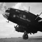
canberra kid Posted September 19, 2021 Share Posted September 19, 2021 This may be of use too. Though it's a B.6 B(I)8 hybrid apart from the nose she's all B.(I)8. John 3 Link to comment Share on other sites More sharing options...
canberra kid Posted September 19, 2021 Share Posted September 19, 2021 10 hours ago, stever219 said: "Silver Canberras weren't bare metal, they were painted High Speed Silver, an aluminium-pigmented finish that gave a slight sheen rather than a shiny finish and was applied as an anti-corrosion measure. On many silver, and some camouflaged, Canberras the forward section of the fin was painted grey, somewhere near Medium Sea Grey, being constructed of plywoodrather than aluminium. All true Steve, I think @opus999 was referring to the RB.57E which would have been unpainted Aluminium, though the Americans did start to apply paint to some areas on the Canberra due to corrosion issues. John 2 Link to comment Share on other sites More sharing options...
stever219 Posted September 19, 2021 Share Posted September 19, 2021 18 minutes ago, canberra kid said: All true Steve, I think @opus999 was referring to the RB.57E which would have been unpainted Aluminium, though the Americans did start to apply paint to some areas on the Canberra due to corrosion issues. John Thanks @canberra kid I never realised that the B-56s were naked ally. Did they have the wooden fin structure though, or was that replaced by ally? 3 Link to comment Share on other sites More sharing options...
canberra kid Posted September 19, 2021 Share Posted September 19, 2021 31 minutes ago, stever219 said: Thanks @canberra kid I never realised that the B-56s were naked ally. Did they have the wooden fin structure though, or was that replaced by ally? The Martin Canberra had a tin fin from the start, the Australian Mk.20 also had one retrofitted around the time they want to join the scrap in SEA. John 1 2 Link to comment Share on other sites More sharing options...
k5054nz Posted September 20, 2021 Share Posted September 20, 2021 I'm very interested in this build as I have the Frog in my stash awaiting my subject (WT346 for those playing at home) to be repainted. 3 Link to comment Share on other sites More sharing options...
Brigbeale Posted September 21, 2021 Author Share Posted September 21, 2021 I’ve been pondering what to do with the panel lines since reading that they were very fine in detail and probably wouldn’t be seen. After looking at @canberra kid’s website and using the schematic drawing of the Canberra XH234, I decided to scribe the darker lines and transport joints. I think I’ve pulled it off, but we’ll see once the primer is applied a lot later on……. After finishing the fuselage re-scribing, I set about the start of adding some better looking cockpit detail which I intend to 3D print. I also would like to add a bomb bay of sorts - not 100% to the detail accurate - just enough to appear correct. I started by measuring the internal circumference of the front of the bomb bay opening (I just measured top to bottom of the fuselage with my callipers and got the measurement of 25mm). I then cut a card circle and trial fitted it - perfect, so I then cut a piece of styrene 0.5 card. That fits ok in one direction so I marked it so I could fit it later. The rear of the bomb bay was slightly smaller so I noted that inside the fuselage. Also the nose section was measured to add the floor (just in case it can be seen). Once I’ve got the bare bones of the internal structure, I can see where I’ve got to add the nose weight. I fitted the kits pilot ‘seat’ back to the floor section. This will give me some indication of where the seat would have fitted - it maybe wrong but we’ll see, although I’m still waiting for the Pavla seat to show up. 7 Link to comment Share on other sites More sharing options...
Hook Posted September 21, 2021 Share Posted September 21, 2021 Nice progress! Incidentally, the Airfix decals are on the way since this morning. Cheers, Andre 1 Link to comment Share on other sites More sharing options...
bigbadbadge Posted September 21, 2021 Share Posted September 21, 2021 Great progress so far Chris 1 Link to comment Share on other sites More sharing options...
canberra kid Posted September 21, 2021 Share Posted September 21, 2021 Nice work Brian! John 1 Link to comment Share on other sites More sharing options...
Brigbeale Posted September 22, 2021 Author Share Posted September 22, 2021 This is the starting point of the replacement cockpit enclosure. It’s probably going to change in some detail as required when the ejection seat gets added along with instrument and switch panels. I need to knock out two tabs either side on the front to allow for the original flight deck mounting tabs. 3 Link to comment Share on other sites More sharing options...
Brigbeale Posted September 22, 2021 Author Share Posted September 22, 2021 (edited) The cockpit was tweaked in its design to fit inside the fuselage. After 3D printing the part again with the modifications, it appears to fit in reasonably well. I changed the colour of the filament to enable the camera to take better photos. I fitted the two halves of the kit main wheels together, sanded them smooth at the joint and painted them - Nato black for the tyres (my Revell Anthracite has set solid even thought the top was properly secured so I need a new pot), aluminium for the centres with a light wash to highlight the detail. Also the Pavla ejection Seat arrived today. It was sent in an oversize box which protected the rigours of the postal system. Hopefully it’ll fit nicely in the cockpit. Edited September 22, 2021 by Brigbeale 6 Link to comment Share on other sites More sharing options...
Brigbeale Posted September 23, 2021 Author Share Posted September 23, 2021 (edited) There’s not much to report tonight as my neighbour decided it would be a good time to discuss which of his two cars he’d want repairing first🙄. I just about managed to add the lower front floor to the design before the doorbell went. When I eventually got back in, I looked again at the previously printed part and decided to increase the diameter by 0.5mm for a better fit. As I type this, the next incarnation of the crew area is printing. It should turn out a lot better than the previous print as I suddenly remembered that although I changed the nozzle yesterday from 0.4mm to 0.2mm, I forgot to change the setting in the slicing program, so I was printing with a 0.2mm nozzle on 0.4 settings.😖. It did the job but it wasn’t pretty. Edited September 23, 2021 by Brigbeale 4 Link to comment Share on other sites More sharing options...
bigbadbadge Posted September 23, 2021 Share Posted September 23, 2021 Cockpit printing looks interesting, great work. Chris 1 Link to comment Share on other sites More sharing options...
Brigbeale Posted September 24, 2021 Author Share Posted September 24, 2021 I got up this morning and after doing the usuals, I took a peek at the 3D printed cockpit assembly. It did look better now the correct settings were used. I just had the supports to remove (as is nigh impossible the printer to print large overhangs in mid air). I offered it up to the fuselage and (despite bending the front floor up a bit, it fitted very well. A bit of sanding at the very front might get it to sit better, but as it’s basically going to be very dark inside, I can be left - but It will probably bug me if I leave it. I placed the nose wheel bay/door assembly roughly in position to see if it still would fit. 5 Link to comment Share on other sites More sharing options...
FZ6 Posted September 24, 2021 Share Posted September 24, 2021 Looking great. I have one of these to do and am looking at using m recently found CAD skills to create a cockpit for mine. if it’s not too late, the bulkhead forward of the wheel bay should be sloped. However not a lot will be seen once it’s closed up so this might not be noticeable. 1 Link to comment Share on other sites More sharing options...
Brigbeale Posted September 24, 2021 Author Share Posted September 24, 2021 I did plan to do the bulkhead sloped but I also had I’m mind the amount of nose weight needed, and also it won’t be seen as I’ve tried the canopy on and could hardly make out any detail as it was - let alone when it’s painted black. Link to comment Share on other sites More sharing options...
bentwaters81tfw Posted September 24, 2021 Share Posted September 24, 2021 I built this years ago, and used the un-bulged bomb bay doors. Not the best fit, you will need to make some adjustments. Turned out OK. I re hashed it later with some Model Decal improvements. 1 Link to comment Share on other sites More sharing options...
opus999 Posted September 24, 2021 Share Posted September 24, 2021 Looking good! That 3D printer sure comes in handy. 1 Link to comment Share on other sites More sharing options...
Brigbeale Posted September 26, 2021 Author Share Posted September 26, 2021 (edited) Work progressed on the cockpit this week despite various interruptions from family members and neighbours. The previously mentioned ejection seat was painted with Tamiya flat black. The seat belts should have been painted blue, but as I didn’t have blue, I used cockpit green instead - maybe not the best but they’re ok. The seat was then dry brushed with Tamiya Sky grey. That made the detail stand out better. The next thing was to design and 3D print the cockpit sides. The left hand console was simply a rectangular strip with some implicated detail on the top. It could have had more but I didn’t want to overdo it. Tonight I designed the right hand side of the cockpit. The design was ok, but the print had a bit of stringing which I kind of preferred as the circles and rectangles were almost non existent once printed. i used my sprue goo to fit the two sides of the cockpit in remembering to leave a gap wide enough for the ejection seat. The seat was dry fitted into the assembly which in turn was dry fitted into the fuselage. I need to make an instrument panel which fills the slight gap at the front of the cockpit and a cover/bulkhead for the rear. The canopy was also dry fitted and I’m happy to say the seat fits without touching the canopy itself. I might have a spare joystick somewhere to fit in as well. Edited September 26, 2021 by Brigbeale 5 Link to comment Share on other sites More sharing options...
TheyJammedKenny! Posted September 27, 2021 Share Posted September 27, 2021 Nicely done. You probably know this already, but the Canberra had more than just a stick. It had a small yoke, similar to that on the U-2, and it's easy enough to make. Amazing to me how the pilot ever got into the ejection seat, because the canopy on these things was not designed to open. He must've been a contortionist! 1 1 Link to comment Share on other sites More sharing options...
bigbadbadge Posted September 27, 2021 Share Posted September 27, 2021 It does look good. The seat will add a nice focal point in the cockpit too. Great work. Chris 1 Link to comment Share on other sites More sharing options...

Recommended Posts
Create an account or sign in to comment
You need to be a member in order to leave a comment
Create an account
Sign up for a new account in our community. It's easy!
Register a new accountSign in
Already have an account? Sign in here.
Sign In Now