cropredy Posted June 4, 2021 Share Posted June 4, 2021 Hi, I decided to challenge myself by trying to replicate a Gerald Scarborough Airfix Annual #5 1975 scratch build of a Robey Gunbus on a trailer towed by a Daimler lorry. I guess this was the time when scratchbuilding was the norm for "real modellers" - or at least those that subscribed to the Airfix Magazine. You can see the prototype and Scarborough's finished model below. There's no kit of this model in 1/72. The Airfix Annual includes scale plans that I used for dimensions. This was not trivial work and "mistakes were made". As this is the first WWI biplane I've ever built, there's one detail about the rigging that I don't understand despite staring at the plans, examining photos, and inspecting the photos of the Stephen Foster Gunbus scratch build . Specifically, there are control horns on each side of the nacelle (not yet added on my model). Here's a screen shot from Foster's model showing what I'm talking about (see red arrow). My rigging questions are: Q1: Where do the two cables from the top/bottom of the control horn go? From pictures, they seem to go to the forward inner strut affixed to the fuselage but then where? Q2: Some cable(s) must attach to the rudder. Where is the other end of these cables? How did those cables avoid the pusher propeller? Progress to date ... 5 Link to comment Share on other sites More sharing options...
Paul Thompson Posted June 4, 2021 Share Posted June 4, 2021 I remember that article well. Always meant to try it, never did, so it's nice to see you giving it a crack. The horns you refer to are for the elevator. Same as for the rudder they'll most likely run to pulleys secured to a convenient interplane strut, and from there either directly to the elevator or with the aid of one or more extra pulleys along the booms. You should be able to follow the route Mr Foster used if you enlarge his photos (Ctrl + is the most convenient way). I can't see how they rn from the plans - they show the cables running straight back from the nacelle to the lower wing at the level of the first interplane strut, then by the second they run nack along top of the booms, crossing on the way. You can't tell from the photos of the real thing, but I'd suspect these cables to be disconnected while the aircraft was being transported. On the plan they don't connect up to the tailplane. The rudder control horn can be seen on the plan as at the second rib going up the rudder. The cables on the plan are parallel to the struts from above, and running to the rear trailing edge strut in profile, where they get lost. A cable appearing out of the nacelle side just above the base, 3/4 of the way towards the back of the rear cockpit openeing may be the rudder cable heading to the bottom of the front strut before the boom, but it could also be the aileron control cable. Altogether, quite a puzzle. I'm sure when I look again I'll come to different conclusions. I'll keep looking. Paul. Link to comment Share on other sites More sharing options...
Paul Thompson Posted June 4, 2021 Share Posted June 4, 2021 I've just found a clearer diagram in 'Sopwith - The Man and His Aircraft', and it shows that the cables exiting in the vicinity of the rear seat can't be the rudder cables. They run to pulleys under the lower wing, level with the first interplane strut (I'm calling the very first pair of struts alongside the nacelle centre section struts) and from there to pulleys level with the 2 control horns on each lower aileron, then back to said control horns, and then to the top aileron horns. They then run across the top wing to complete the circuit, held down by fairleads. If you're unfamiliar with the system, any decent photo of an Avro 504 should show you how it looks. Still no idea about where the rudder cable emerges though, or the precise routing of the elevator cable. Paul. Link to comment Share on other sites More sharing options...
cropredy Posted June 5, 2021 Author Share Posted June 5, 2021 (edited) Paul This is helpful -- I did Ctrl + on the first image in Foster's build and I can see the elevator cables going to the 3rd interplane strut (counting from the outer wing edge). Since this part of the wing is not even on my build, I think I will attach the elevator control horns to the nacelle and not bother with any rigging to said control horns as otherwise one end would go into "space". Less-is-more! Oh, but wait, the original photo shows the cables going to the 4th interplane strut (counting from the outer edge, or the first interplane strut by your definition) so less-is-not-more and they're back on my build list. Sigh. As for the rudder cable, I see what you mean after enlarging the photos, it sort of disappears around the 3rd boom strut (counting from the back). Be interesting to see what you think of this part (see red arrow) of the original photo. Scarborough made no mention of it but it looks like the elevators lying on top of the boom. I'm sort of wishing it away (as I am the undercarriage wood bracing in the photo) because if Scarborough didn't do it, I'm not doing it (said petulantly). Edited June 5, 2021 by cropredy correction 1 Link to comment Share on other sites More sharing options...
Alfisti Posted June 5, 2021 Share Posted June 5, 2021 There is an interesting article on the ww1aircraftmodels.com web site.In the Aircraft Information/Questions section,under 'WingNutWings FE 2b,another problem',there are some good photos of the control line/cable system used and the pulleys etc. Dave. 1 Link to comment Share on other sites More sharing options...
Paul Thompson Posted June 5, 2021 Share Posted June 5, 2021 2 hours ago, cropredy said: Be interesting to see what you think of this part (see red arrow) of the original photo. Scarborough made no mention of it but it looks like the elevators lying on top of the boom. I'm sort of wishing it away (as I am the undercarriage wood bracing in the photo) because if Scarborough didn't do it, I'm not doing it (said petulantly). Interesting. Definately something there, and nothing where the tailplane and elevators should be. Funny how you can stare and stare at something, and over time what was obvious just isn't any more, and I've stared at the whole article a lot since 1975. It doesn't seem a very safe way to transport the assembly, but there's so little detail visible I can't even guess how it was attached. It has to be tied down somehow. Neither can I say if it's the whole thing or not. I suspect the elevators have also been removed and salted away elsewhere. Usually, when these sorts of external elevator cables are disconnected, they're coiled up at the rocker end, but here they've clearly been run somewhere else first. The loose bits must still be coiled though. Okay, this is stream of conscious over the first coffee of the day, but looking at the photo top of page 52, I think what I'm seeing is the whole tailplane assemny, with one of the control horns sticking up. Must be ropes or leather belts there somewhere, but that's guesswork. Oh. And where the outer wing panels attach, there seems to be a pulley doing nothing either side of the top centre section. Ahem. And what looks like an extra strut, but seems really to be part of a square framework that the front of both wings is butted up against. I think that's what you can see instead of the leading edge of either wing. Must be there to stiffen the structure for transport, but I can't see how it's attached to the trailer. Could be the same coloured wood as the similarly sized truss that the back end is propped up on. Got to walk the dog. I'll have another look later, but for now, I just noticed what may be something behind the port elevator rocker, but could instead be the lower cable, and it seems to head off downwards.................. Paul. Link to comment Share on other sites More sharing options...
cropredy Posted June 5, 2021 Author Share Posted June 5, 2021 Quote And what looks like an extra strut, but seems really to be part of a square framework that the front of both wings is butted up against. I think that's what you can see instead of the leading edge of either wing. Must be there to stiffen the structure for transport, but I can't see how it's attached to the trailer. Could be the same coloured wood as the similarly sized truss that the back end is propped up on. I think you are right about that rectangular framework now that I look at it again, and why I didn't realize it before I did the interplane rigging (!!). It also would have served as a brilliant jig while aligning everything during construction. Do I add it now? I so much want to be done with this model. I've still got to do the stencils for the wing carrying box plus the whole diorama scene. The endless dilemma for the hobbyist. I think I'll give it a dry-fit go and see if I can make it work. As for the tailplanes atop the boom, they're easy enough to make and I would imagine as did you that they would have been secured by ropes to the boom. No Velcro in 1915. Will certainly make for a more interesting depiction. Link to comment Share on other sites More sharing options...
pheonix Posted June 9, 2021 Share Posted June 9, 2021 Dear Eric, My apologies for the delay replying to this topic- I have only just seen your question about the control cables on the Sopwith Robey Gunbus. Thank you for referring to my amateur attempt to convert the Airfix Avro 504 into one of these unusual machines - I am afraid that looking at the photos of my model will probably not provide the answer to your question about the control cables to the tail. I will try to explain why. First however the aileron control cable arrangement described by Paul in the thread is exactly how I interpreted it - the cable probably exited via a hole in the elevator control horns and went to the leading edge of the lower wing at the first strut from the fuselage. (NB I have only just realised that these are absent on my model! They are also absent on the drawings, but this was the usual exit point on pusher aircraft - see for eg the Vickers FB5 Gunbus, FE 2b, etc). From there it ran along the leading edge of the wing, (or just underneath it), and then via pulleys to the control horns on the underside of the ailerons. Two wires joined the upper and lower ailerons and two more wires ran to pulleys on the leading edge of the upper wing. The wires then ran along the top of the wing to complete a loop - the wire on the top of the wing was known as the balance wire and was frequently used on pusher aircraft and some tractor types too where there were ailerons on both wings. The balance wire is on the plan drawing. The elevator control wires also seem to have followed the pattern of other contemporary and slightly later pushers. They were taken from the control horns close to the fuselage to pulleys attached to the fuselage frame just to the rear of the front pair of "cabane" struts ie the struts closest to the nacelle. (A similar arrangement was followed on the Vickers FB5 Gunbus except that on that machine they were taken to the rear cabane strut). From there they were carried upwards across the bay between the "cabane " struts to the upper ends of the rear pair of first of the true interplane struts. At that point they were passed over pulleys which led to the elevators. If you look at N. Franklin's drawings you can see the run of the cables from the elevators forward to the rear interpane struts on the side elevation, but for reasons which I do not understand they are absent on the plan drawing. The rudder cables exited the fuselage nacelle just to the rear of the pilot's seat - they were probably carried internally in the nacelle from the rudder bar to the exit hole. They can be clearly seen on the plan drawing. They passed to the bottom of the first of the front interplane struts, where they passed via a pulley to the rear strut and then, also via a pulley to the rudder. If you look carefully at the photo on p 46 (3845), the rudder cable can be seen passing from the control horn on the rudder to the base of the rear interplane strut and into the fuselage nacelle. Note that the rudder has been pulled around so that it is not in the neutral position as Scarborough modelled it. The rudder cable is taught - clearly it is holding the rudder in place. However the photo on p 49 of 3846 seems to show the rudder in the neutral position. I am not sure about your interpretation of the elevators on the booms in the photo on p 46. Looking at them they seem to be the wrong shape and I would err towards Paul's interpretation that they were more likely to have been the horizontal stabilizers, not least because they would not have had control horns to get in the way. Sadly I do not have the Sopwith book referred to by Paul where the photos are also reproduced, and I do not know where better images may be found which might conceivably answer the question. Interestingly the photo of Scarborough's model is at such an angle that what he has put there is unclear! I wish to stress that all of the above is my interpretation of the drawings and photos in Airfix Magazine Annual, (which are traced from those in "Sopwith and his Aircraft"), and a couple of additional photos of the convoy which I found on the net when I made the model around 8 years ago. Remember that it is very unlikely that manufacturers drawings exist - indeed they may never have done so as Sopwith stated in an interview given towards the end of his life that his earliest designs did not have proper drawings: rather they took the form of detailed sketches! I suspect that the drawings we have are based on photos and published dimensions: hence some of the ambiguities about them. If you are making your model in 1/72 scale many of the very small details such as pulleys etc can be left off as the originals were very small indeed and would be barely visible in this scale. Similarly if you are representing the model on a trailer, you would only need one rudder cable if you are modelling 3845 and the elevator and aileron cables would be absent - probably rolled up and stored as Paul has suggested. However you choose to represent the model it is worth remembering that we are all using the same very limited sources of information and so there is considerable room for honest disagreement. As with so much from this period there is an absence of clear evidence so that modellers like us are forced to use guesswork, comparison with contemporary types and license to show what we think it may have looked like. I can provide more photos of my model if you wish me to, but I would ask that you remember that this was not one of my better conversions: I had only returned to modelling for a year when I made it and it was the 4th pusher conversion that I had attempted since my return. I just hope that the above notes may be of help to you - certainty I cannot provide, but I fear that nobody else can either because we simply do not have enough clear evidence. P 1 Link to comment Share on other sites More sharing options...
cropredy Posted June 17, 2021 Author Share Posted June 17, 2021 Well pheonix, thank you for the reply -- sadly, by the time I read this, I completed the rigging as best I could imagine and in the process, dislodged existing rigging. I'm at the end of my rope, so to speak. Please don't sell your Sopwith Gunbus efforts short. Far better results than I have obtained. Here's where I have ended up with a couple more questions First, I added the wood frame around the leading edge as is clear in the original pictures. Thanks Paul! Second, in order for the tailplane to rest on top of the boom, it was clear to me that there would need to be a supporting cross piece. Since other photos of the Gunbus do not show a cross boom piece, I added a piece of styrene rod that looked like the same wood used for the trailer: This then allows me to do this (not yet glued): The tailplane does not extend the width of the load so it would still fit as the lorry traversed narrow roads. So ... you suggest that it would only be the stabilizer on top of the boom, not the whole tailplane? Since the reference photo is edge-on, it is impossible to tell. I couldn't find any references on how biplanes were transported by lorry to gain any insight here. And, the reference photo doesn't seem to show any ropes used to hold this down but admittedly, the images are grainy. Any insight as to how this might be done? The boom is a VEE shape looking down and I don't know how they could have tied it down without the ropes slipping towards the boom's vertex or slipping across the tailplane edges. 2 Link to comment Share on other sites More sharing options...
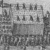
pheonix Posted June 17, 2021 Share Posted June 17, 2021 Thank you for the kind comment about my model. Just a small point about yours: you have omitted the cross bracing on the front bay of the boom - check the plans - these were extended to the rear interplane struts when the outer wing panels were attached. If you look closely at the Gunbus on the left of the photo there are two beams across the upper boom supporting the tailplane. The forward one is just in front of the boom strut, the rear is just behind the middle boom strut. However I can see no evidence of how the tail unit was held down, but is it possible that as these machines were not being transported for a long distance, the weight of the tail was sufficient to prevent it from moving and falling off. This is just a suggestion but I think a possibility as these machines were being moved from the factory to a nearby airfield for re-assembly and flight. Congratulations on your attempt - that is a cracking model and I for one would like to see more pictures if you would post them. P Link to comment Share on other sites More sharing options...
Paul Thompson Posted June 17, 2021 Share Posted June 17, 2021 49 minutes ago, pheonix said: If you look closely at the Gunbus on the left of the photo there are two beams across the upper boom supporting the tailplane. The forward one is just in front of the boom strut, the rear is just behind the middle boom strut. However I can see no evidence of how the tail unit was held down, but is it possible that as these machines were not being transported for a long distance, the weight of the tail was sufficient to prevent it from moving and falling off. This is just a suggestion but I think a possibility as these machines were being moved from the factory to a nearby airfield for re-assembly and flight. Possibly, but I'd think it the proverbial accident waiting to happen - imagine, gust of wind plus loose flying surface................. And since they went to the trouble of constructing frameworks for the transport it seems to me at least likely there are straps at least for security. Have to have a crack at this myself now, due to you and Eric. Plus, I have a Pegasus FB5 my son knocked on the floor by accident some 10 or so years ago - tempted to make a diorama of everything in that last photo. It would keep me good for a while.............. Paul. Link to comment Share on other sites More sharing options...
cropredy Posted June 18, 2021 Author Share Posted June 18, 2021 OK, Just to confirm: I'm missing the 4 red lines (cross-rigging)? When I looked at the plans, I guess I assumed they wouldn't exist without the outer wings attached but that seems naïve now. Oh boy, another chance to knock off existing rigging. You are saying I need another cross wood beam (green line) atop the boom? There's always the possibility there were some fittings on the tailplane designed to lock into some fittings on the wood cross supports. These wouldn't be visible in the picture. Maybe with the second wood support, I could do an X pattern with rope that might be believable (you can tell I'm not the kind of guy with experience tying mattresses down to car roofs). I have plenty of build pictures and narrative (e.g. the ups and downs) that are being assembled into a Wordpress blog - just waiting to get these final bits on before "Publish". I'll link to it with some highlight pictures in the forum. Paul -- I too am doing the diorama - trailer+lorry+GunBus+road+trees/foliage. I found this photo to be entrancing as it is a mix of aeroplane + old-timey transport. Trailer is done; lorry is done except for the carrying box which still needs a stencil for the lettering - say hello to my next purchase - a Silhouette Portrait. Then the landscaping/hardscaping. But I'll publish Gunbus photos beforehand. The Pegasus Vickers FB.5 kit is "substandard" - moldings are thick and clunky. White metal bits are good though and I used some of it on the Robey Sopwith Gunbus Thanks for all your sage advice. 1 Link to comment Share on other sites More sharing options...
pheonix Posted June 18, 2021 Share Posted June 18, 2021 Your points 1 and 2 are correct. I think it highly unlikely that the boom rigging would have been dismantled when the wings were removed, but then I have never been involved in moving a pusher biplane on the back of a lorry! I think that your suggestion that an x pattern for the rope is as good as any. Given the lack of evidence, I dare anyone to challenge your interpretation: should they do so ask them for the evidence! Having seen the pictures of your model so far I am now very keen to see the completed vignette. I do not usually make scenes like this - they are far too difficult for me - the only dio that I have made was for a Dornier flying boat on a turntable at Seemoos (Lake Constance), but that involved building wood structures and a simple grass base - no trees or complicated vehicles. Please post any links here so that I and others can view the pictures and log. It would be easier to convert an FB5 from an existing kit, (Airfix DH 4 in my case), than try to rectify the errors of the Pegasus kit. Conversions like that are not as difficult as people imagine them to be, even if the model in question is a pusher. Simple techniques and tools and a little patience are all that is required. P Link to comment Share on other sites More sharing options...
Paul Thompson Posted June 18, 2021 Share Posted June 18, 2021 2 minutes ago, pheonix said: It would be easier to convert an FB5 from an existing kit, (Airfix DH 4 in my case), than try to rectify the errors of the Pegasus kit. Conversions like that are not as difficult as people imagine them to be, even if the model in question is a pusher. Simple techniques and tools and a little patience are all that is required. P To be honest I didn't find the Peggy FB5 too bad. The 1/48th offering though was way cruder and actually had less detail aand much poorer moulding overall. Maybe Eric had a particularly bad moulding, Pegasus kits deteriorated rapidly over the course of the production run. No, the hardest part for me was figuring out the rigging (now where have I heard that before?), particularly the loom that goes from bottom rear of the nacelle to the wing. Anyway, I'm thinking without checking that revamping this slightly mangled model may be easier than starting again or scratching it. A few saw cuts, replace the broken struts, minor repaint and easier to get at to re-rig it. Just a thought at this stage. Very happy to have observed this build and looking forward to seeing the finished dio. Not all those old Airfix projects ended happily - I'm currently engaged on an Avro 504 conversion to the Cierva C8R, and there are quite a few things glossed over (and just plain impossible) in the article (February 1970), I turned up while bumbling helplessly around the internet. Paul. 1 Link to comment Share on other sites More sharing options...
cropredy Posted June 25, 2021 Author Share Posted June 25, 2021 With much trepidation (the old modeler's lament - I'm so close to finishing, I don't want to inadvertently break something), I added the missing cross-brace rigging and tied down the tailplane. Haven't yet cut the cord, so-to-speak, as you u can see in the photo. Rope was Syren Ship Model Company 0.20 mm rope (sadly, no longer available) dyed with Vallejo brown wash. I'll be setting the Gunbus aside for a bit while I turn my attention to the diorama. Then I will add the wheels and mount to the trailer. I've started on the fence in the background and decided to throw in a couple of Dart Castings Frisian cows. Workbench will need to be cleared for action in order to build the diorama base. Vast quantities of Woodland Scenics stuff has been acquired and I'm watching a bunch of YouTube videos from model railroaders on landscaping techniques. This will be my first foray into a significant "nature" diorama unlike airfields that I've done in the past. 2 Link to comment Share on other sites More sharing options...
pheonix Posted June 25, 2021 Share Posted June 25, 2021 That looks very convincing to me. At least nobody can challenge your interpretation because the photos are so ambiguous. I am really looking forward to the completed dio photos - I am sure that it will be a winner when finished. P 1 Link to comment Share on other sites More sharing options...
Paul Thompson Posted June 25, 2021 Share Posted June 25, 2021 Just make sure the weathering on the cows is right or there'll be hell to pay..................... Paul. 2 Link to comment Share on other sites More sharing options...
cropredy Posted June 28, 2021 Author Share Posted June 28, 2021 Diorama planning .... I decided to add a horse-drawn wagon to add to the old-timey feel. Tree (first attempt) armature following Luke Towan method on YouTube. He recommended 28 gauge floral wire which I didn't have so I used 24 gauge copper wire. This is a pain to bend and twist so I ordered 28 gauge floral wire and will try again. Canopy needs to be broader. Note that scene in picture is clearly late autumn so no leaves for my tree. 3 Link to comment Share on other sites More sharing options...
cropredy Posted July 8, 2021 Author Share Posted July 8, 2021 Slow progress here. Wood base is made; waiting on the Woodland Scenics foam core. First, my initial tree attempt looked like a cypress but the second attempt looks like a tree one would find in Britain and looks sort of like the prototype (28 gauge floral wire was the trick, 18 strands, cut to 15 inch length). I still have to trim the end branches and then prep/paint/weather And, the British Service Wagon from W^D Models is mostly done. These are resin kits that are well-engineered and detailed, albeit with a lot of flash to clean up. There's nothing like working for hours with your scalpel carefully shaving off flash while avoiding self-surgery. The white metal horses are very-well molded and believable, especially in 1/76. My wife pointed out the horses' hooves are the wrong color and I'm fixing that. The horses also need a semi-gloss overcoat. The reins and harness will have to wait until the wagon and horses (with white metal base detached, of course) are emplaced on the diorama as rein/harness length depends on exact placement/orientation of the wagon and horses. I haven't figured out what I'll use for the reins, perhaps .010 x .010 rod which naturally sags; or, maybe thread is a better idea. I'm open to ideas. I opted to order the Silhouette Portrait (to cut the Robey Aeroplane - Lincoln stencil mask) from MicroMark to support retailers that cater to modelers. Of course, since Micromark is probably at the bottom retailer tier for Silhouette's distributors, it is out of stock. 3 Link to comment Share on other sites More sharing options...
pheonix Posted July 8, 2021 Share Posted July 8, 2021 Both the trees and the horses/wagon look super. I would suggest 10 x 20 thou strip for the reins as they would be leather straps and flat not round. Alternatively if you have the patience(!) you could cut strips from 5 thou card to make the reins thinner!! Looking forward to more updates. P Link to comment Share on other sites More sharing options...
cropredy Posted July 11, 2021 Author Share Posted July 11, 2021 I like the .005 card idea for the reins as flat would be the look and at that thickness, they'll definitely droop. Good use for my Infini Cutting Mat. Meanwhile, one of the Robey Gunbus photos includes two drivers standing together, probably taking a break. So, I dug into my collection of 1//72-1/76 figures and came up with one from the Airfix Civilians set and one from Langley Models Working Figures 2. The Airfix figures are notorious for being unsandable and resistant to paint. You can see in the picture to the right of the figure a coating of clear plastic that I scraped off with my scalpel. The whole figure needed shaving and even still, there are tiny bits sticking up. Do not buy this set! But, the guy looks a lot like the prototype driver. Here are both of them painted. First time I've had to do mustaches. Not easy in 1/76. In terms of detail: W^D resin > Langley white metal > airfix 1962 plastic 5 Link to comment Share on other sites More sharing options...
cropredy Posted August 14, 2021 Author Share Posted August 14, 2021 After much procrastination, I feel like the project is shovel-ready for the diorama. I built a simple base and used a high density foam core base from Woodland Scenics. In order: Layout planning with the actual figures and vehicles Starting with the road Adding terrain (Sculptamold) and the fence Painting the base layer Adding grass, shrubs, and a pond (Woodland Scenics Realistic Water) Adding leaves under the tree (it is November) Making sure the image I'm using for the lorry's container fits properly. This will be used as a stencil for my brand new Silhouette Portrait 3. I worry the stencil will be too hard to cut. On the to-do list: Cutting the stencil and then painting the lorry container with Robey Aeroplane - Lincoln Putting the wheels on the Gunbus and mounting to the trailer Adding the lorry + trailer to the layout Adding a load to the wagon (I've got lots of food bins ready) Adding a road sign indicating a stop somewhere between Lincoln and Newark. Tiny dry transfer font here - what fun Placing the wagon and horses and adding the harness connecting the three (this will be tricky) Placing the figures Removing the base's masking and doing whatever touchup is required Final photos 4 Link to comment Share on other sites More sharing options...
pheonix Posted August 14, 2021 Share Posted August 14, 2021 That is superb. A wonderful dio in the making - cannot wait to see it finished. P Link to comment Share on other sites More sharing options...
AWFK10 Posted August 15, 2021 Share Posted August 15, 2021 This is really looking great. Can I just make a suggestion about, of all things, the road sign? I know Lincoln quite well, including the spot where these photos were taken. Hopefully this link will take you to the relevant Google Maps view. The location is the corner of the B1138 and South Park, towards the bottom right (where it says "Canwick Court Care Centre Lincoln"). The lorries are turning into South Park and the photographer is looking out across South Common towards the rising ground where the International Bomber Command Centre is today. Those industrial buildings just above the cemetery are what were then the Robey & Co works. The convoy has travelled only a few hundred yards and I think the sign visible in the photos is the street name for South Park. Old OS maps show that the Robey factory had its own railway sidings, so the aircraft aren't being dispatched for shipment (they were delivered to the RNAS Central Stores Depot at White City, in London). If we zoom out a bit, you'll see Bracebridge Heath at bottom centre. That was the site of Robey's airfield, so it's a safe bet they're being towed there along South Park and then up what's now the A607 to be test-flown before being returned to the works and shipped out by rail. Just for interest, my grandfather did his recruit training in Lincoln at the end of 1916 and was billeted in the racecourse grandstand across the road from West Common, which was being used as an Aircraft Acceptance Park. He'ld have seen 1½ Strutters and BE2s being test-flown. 1 Link to comment Share on other sites More sharing options...
cropredy Posted August 16, 2021 Author Share Posted August 16, 2021 @AWFK10 - Well, the last thing I thought I would ever hear is an exact location of the road intersection from an expert! Having just watched an episode of the BBC's "Fake or Fortune" where "provenance" is oft-used, I can't ignore this new evidence. Although I've already made the road sign, I've spent a year on this project so another day at the bench is just a blip in the modeler's craft. Thanks for the input! Some photos of the mask making Screen shot from Silhouette Studio showing the power of the tracing tool from a JPG image (there was some line editing as well to smooth out the jaggies) Silhouette Portrait 3 in action using Tamiya masking sheet. I used the OOTB cutting mat which is very tacky (sticky) despite repeated attempts to soften. I ordered a low-tack mat to try for my next project. I can see why folks paint their markings on planes rather than use decals. Masks affixed to lorry container box. Painting to follow (earlier, without photo, I did a test mask on brown-painted sheet styrene and sprayed a light brown undercoat to seal the edges, then white overcoat; after peeling off the mask, results were excellent) The The whole process of using the stencil cutter was completely new to me and I never would have done it had not I concluded the container's lettering looked hand-painted, probably from bespoke factory stencils. I'm trying to follow the mantra of the podcasters from "Plastic Model Mojo" who say "What are you going to do to get better?" when tackling each modeling project. For this project, no shortage of new things to learn aim towards proficiency. 1 Link to comment Share on other sites More sharing options...

Recommended Posts
Create an account or sign in to comment
You need to be a member in order to leave a comment
Create an account
Sign up for a new account in our community. It's easy!
Register a new accountSign in
Already have an account? Sign in here.
Sign In Now