JWM Posted April 27, 2021 Share Posted April 27, 2021 (edited) Hi, My next input to this GB is a double build of Caproni upper wing three engines machines from Italo-Etiopia war in 1935-36. I have two kits of Caproni 101 by Fly in 1/72 One I am going to do OOB or almost OOB. The second one I am going to convert into Caproni Ca 133. On above photo you may see an Italian monograph on Capronis and the background and drawings from another Italian monograph of Caproni Ca 133, issued in series Ali d'Italia The conversion of Ca 101 into 133 requires a lot of work - larger wingspan, extended fuselage, different struts, larger engines, larger tailplane etc... There is no too much time, so I am not sure if I will manage to fit in time, especially that within "Anything but injected" I want to construct in parallel another Caproni - The Ca 111, single engine sister of those two by Broplan vacu. This another GB ends month later so maybe in some moment I will stop work on Ca 111, not to slow those two... To be continued Regards J-W Edited May 2, 2021 by JWM correction in topic 9 Link to comment Share on other sites More sharing options...
JWM Posted April 28, 2021 Author Share Posted April 28, 2021 After some consideration I think that although the Ca 101 will be in colonial style scheme from campaign 1935-36: like above or similar (I am not decided yet), the Ca 133 will be rather not in such "anti camouflage" but rather from 1940-41 British liberation of Abyssinia war like that: or that or that http://img.wp.scn.ru/camms/ar/1/pics/32_2.jpg Regards J-W 3 Link to comment Share on other sites More sharing options...
JWM Posted April 28, 2021 Author Share Posted April 28, 2021 As I already mentioned the Ca 133 has larger wingspan Since I will need the surface details I will try to reproduce structure of wing in resin. To get it I covered a piece of wing with silicone to get form for resin The tailplane of Ca 133 is the same as in Ca 111, so I am copying in resin the taiplane of Ca 111 by Broplan We need few days, up to week to get silicone perfectly dry... To be continued regards J-W 3 Link to comment Share on other sites More sharing options...
PeterB Posted April 28, 2021 Share Posted April 28, 2021 Reading up on my SM 81 I gather that they supplemented the Caproni Ca 133 but that the Caproni remained the main bomber in the Italo-Ethiopian War? Pete 1 Link to comment Share on other sites More sharing options...
JWM Posted April 29, 2021 Author Share Posted April 29, 2021 7 hours ago, PeterB said: Reading up on my SM 81 I gather that they supplemented the Caproni Ca 133 but that the Caproni remained the main bomber in the Italo-Ethiopian War? Pete I think so. At the beginning of this war (1935) no SM 81 was involved there, they appeared later but still different variants of Capronis were the working horses there - as machines designed purposely for colonial use. When British army came into actions in 1940 of Capronis only 133 (and smaller 309) were there, the Ca 101 and Ca 111 were already phased out. But of course SM 81 were there still. J-W 1 Link to comment Share on other sites More sharing options...
JWM Posted April 29, 2021 Author Share Posted April 29, 2021 (edited) Hmm.... - I am a bit puzzled. Both Italian monographs on Ca 133 on drawings shows 28.8 cm wingspan, what give 20.75 m in real life whereas published data give 21.44 m or 21.24 m. The larger number is given in both Italian monographs a bit shorter value is for example in Wiki or in Czech Valka Web page. I think I will keep the 21.44 m rather then others values (ie. 297.8 mm in 1/72), but any comments on this uncertainty in real dimensions will be welcomed. Of course I have to check scale of drawings regarding the length... Regards J-W Edited April 29, 2021 by JWM 1 Link to comment Share on other sites More sharing options...
JWM Posted April 29, 2021 Author Share Posted April 29, 2021 Result of measurements: it looks that my copies of Ali d'Italia drawings (I work on copies, not with original book) need to be rescaled (4% enlargement). In second monograph the only the picture from front needs similar 4% enlargement, the side views (both for Ca 111 and Ca 133) are ok. Maybe some creative person scaled it down while printing, to have proper size of margines... . Maybe some other reason. Anyway, this problem is sorted. Still I have doubts why two dimensions for wingspan exists in literature for Ca-133, it is 20 cm for 21 metes, so ~1% - to much to come from calculation back and for to British and metric units. It is about 3 mm difference in 1/72 for entire wingspan, 1.5 mm on sides. I think I will believe the Italian number of 21.44 m. To be continued J-W 3 Link to comment Share on other sites More sharing options...
JWM Posted May 1, 2021 Author Share Posted May 1, 2021 The silicone form for tailplane of Ca 133 is ready. The Broplan Cs 111 (vacu kit) tailplane used for preparation of form is visible as well. Later I put the resin into it, tomorrow should be ready To be continued J-W 3 Link to comment Share on other sites More sharing options...
JWM Posted May 2, 2021 Author Share Posted May 2, 2021 I started the extension of fuselage of one Ca 101 to get the Ca 133 length. Fist - the cut right behind the dorsal turret. There is one section added as extension and then we came back to normal fuselage of Ca 101 toward the end. However the whole tail is larger. The Horizontal stabilizer is the same as that of Ca 111, so I am waiting now for resin to fix, but the fin and rudder are neither that of Ca 111 nor that of Ca 101, however there is a huge similarity in style. I thinned the inner sides of existing fin an cut out the proper shape from ~0.5 mm thick plastic sheet (the not moulded areas of Ca 111 kit). Then I glued the rear part with this new fin placed between old one halves. The rear fuselage extension I am going to do following way. On sides I glued the 0.2 mm thick pieces in which I will reproduced the inner structure. From thicker plates I did top and bottom elements. Then I will dlue on outside plates tho reinforce it and get some thickens and strength, finally the surface if will get from a putty. Here I already put some putty on fin: To be continued Regards J-W 8 Link to comment Share on other sites More sharing options...
JOCKNEY Posted May 2, 2021 Share Posted May 2, 2021 Hi Jerzy Brilliant choice, I have a great book on the Italian airforce from this era, I will see what pictures I can find for you. Really looking forward to these 2. Cheers Pat 1 Link to comment Share on other sites More sharing options...
JWM Posted May 4, 2021 Author Share Posted May 4, 2021 Hi I started work on inside of Ca 101 and found in instruction, tgat there is an error and I should blind one set of side windows and drill the openings in the other place. This made me suspicious a bit and I started to study photos. This draw me to conclusion that all windows are in wrong places. On starboard side I thing there were three windows an port two. Using device for making in leather belt holes I cut out four discs to blind old openings and I drilled new one. If I was right this appear when applying decals The inside - as green Hu 120 as linen Hu 168 Cheers J-W 4 Link to comment Share on other sites More sharing options...
Touvdal Posted May 4, 2021 Share Posted May 4, 2021 That is some covertion job you started there, very impressiv. 😀 Cheers Jes 1 Link to comment Share on other sites More sharing options...
JWM Posted May 4, 2021 Author Share Posted May 4, 2021 Hi The wing of Ca 101 is glued together, so the dry trial with fuselage t see shapes for the first time Some sanding was needed to get expected dihedral. 14 mm - this the size of length extension to get Ca 133 from Ca 101 in fuselage behind wing I did some initial sanding on tailand I blinded all portholes to get freedom of drilling in proper positions. I made large square window on starboard side It is not exactly square from iside, because I cut it relatively to inner structure and then found that vertical bar shoud be about 3 mm more forward, but from outside it will be square due use of filler. I started work on wings extension for Ca 133. It is 12.5 mm (half of inch if you like) each side. So I cut the wing and added supporting plate The surface structure I am intending to reconstruct using thin resin foild obtained using this silicone forms This will be only 4 ribs added each side, so the problem on left side of left form above is easy to ignore. The engines,cowlings (shorted) and props will be resin copies of Italeri Ca 311. Forms are already under preparing: Even the engine gondolas I will prepare based on resin copies of engine nacelles (fairings) from Ca 311 kit. They will need only be shorted a bit in middle. Resin tailplane for Ca 133 (copy from vacu Ca 111) Not assembled yet fuselages of three sisters: Ca 133, Ca 111 (Anything but injected GB) and Ca 101 To be continued Regards J-W 6 Link to comment Share on other sites More sharing options...
JWM Posted May 5, 2021 Author Share Posted May 5, 2021 A work on wings extension. First I cut lower and upper parts of wings in different places, to keep construction strong. Since the module of ribs is 3 mm I did extension for 12 mm. On back sides I glued a piece of plastic card 0.50 mm thick: On external side another 0.5 mm thick small plates were glued as spacers Still there is 0.5 mm space for external lining which I intend to do from resin, thin layer of which I spread on silicone forms: The upper and bottom parts of wings are glued together. And compare of sizes: The wing of Fly model has smaller chord then drawings from Ali d'Italia series. But I believe it is a mistake - from data on wings area and wingspan, assuming rectangle shape (what is almost true) the chord of Ca-133 is a bit smaller then that of Ca-101, so I assumed - are the same. I started to work on nacelles And I drilled portholes/windows No work on Ca 101 (nor Ca 111) today... Regards J-W 4 Link to comment Share on other sites More sharing options...
JWM Posted May 6, 2021 Author Share Posted May 6, 2021 I put the resin "skins" on extension and started correction of shape of wingtips: Ca 101 does not have slats, whereas Ca 133 has (as Ca 111 does to) - this makes that w leading edge goes closer to the end as straight line. To be continued Regards J-W 3 Link to comment Share on other sites More sharing options...
CliffB Posted May 7, 2021 Share Posted May 7, 2021 These aircraft are totally new to me, but certainly tick all the right boxes. Your modifications are very impressive J-W . 1 Link to comment Share on other sites More sharing options...
Col. Posted May 7, 2021 Share Posted May 7, 2021 Great work on these two J-W 1 Link to comment Share on other sites More sharing options...
JWM Posted May 8, 2021 Author Share Posted May 8, 2021 The instrument panels of Fly model Those are both from Ca 101 kits - the Ca 133 should have a more complex one In Ali d'Italia there are drawings ... I am not sure about changing it since it is almost not visible at all... Have to think twice - those are so nice looking... Below the fuselage of Ca 101 is already closed, whereas that for Ca 133 had added frames from scratch Above halves of front part of fuselage for Ca 133 just before closing. And here fuselage of CA 133 is closed, in background the wing with extended span and modified shape of wingtips In Ca 101 all tail is glued together: To be continued Regards J-W 5 Link to comment Share on other sites More sharing options...
JWM Posted May 9, 2021 Author Share Posted May 9, 2021 Fuselage of Ca 133 after first round of sanding, adding filler: For it I am not decided yet about the scheme: Considered options: 1. The upper one from this set (the lower is from BoB! - but I want to do it from Africa...). More or less standard mottled Italian camo from early WW2: it has "variant" with black nose: http://img.wp.scn.ru/camms/ar/1/pics/32_1.jpg 2. Second option - not mottled, colour only deduced http://img.wp.scn.ru/camms/ar/1/pics/32_7.jpg 3. Reverse mottling - dark on light background, very interesting because of black underurface as above one too http://img.wp.scn.ru/camms/ar/1/pics/32_2.jpg 4. The third from the top from this set - with some emblem (devil head?) Any comments on credibility of those schemes? To be continued Regards J-W 4 Link to comment Share on other sites More sharing options...
Col. Posted May 11, 2021 Share Posted May 11, 2021 As an aside to your choices within this GB there's plenty of colour-scheme variety for this type J-W 1 Link to comment Share on other sites More sharing options...
JWM Posted May 13, 2021 Author Share Posted May 13, 2021 As I already mentioned above some my doubts arose regarding the length of the chord of Ca133 and Ca 111 regarding older Ca 101. This happened due to drawings in Ali d'Italia monograph of Ca 133, where the chord is longer that the one for Ca 101 in Fly's kit by about 2.5 mm. Morover, in a Russian web page with description of Capronis I have found a phrase "new wing was installed" in description of Ca 111. Lucky not only the wingspan (21.44 m) but also the wing area of Ca 133 (65m2) are given in technical data of this type. The wing is not exactly rectangle so to determine what is the wing area when calculated from drawings I have used old trick in various instrumental methosds in sciences. In the past, when chemical or physical measurements were not computerized yet, sometimes to determine the area of any kind of irregular shape obtained with analogous instrument (or from map): the gravimetrical method was applied. In other words - the analytical balance was applied. Namely, the given shape can be cut out of a paper sheet, and from the same piece of paper (kept in the same humidity of air, temperature etc.) a rectangle as a reference area was also cut out. The assumption is that the thickness and density of paper are the same, so the difference (or rather ratio) in weights is the difference (ratio) in areas. By the way, the idea comes from (you might be surprised) ... Archimedes of Syracuse! So it has about 2400 years since it was proposed for the first time (but not with paper, which was not discovered yet!) I cut the shapes of wings and also a rectangle 6.9 cm per 13.9 cm - which corresponds to 50 m2 area in 1/72 drawings. The mass of Ca 133 wings-shape piece of paper was 1.0403 g whereas the reference piece was 0.7463 g. This gives (ratio of those masses multiplicated by 50 m2) that area from published drawings corresponds to 69.5 m2, whereas the published in technical data of Ca 133 gives only 65 m2. The difference is 6.5%, what (in first assumption) for a rectangle wing corresponds to shorting the wing chord from 5 cm (as shown on in 1/72 drawings) to 4.75 cm (which is in good agreement with chord of both Ca 101 Fly kit or Ca 111 Broplan vacu)! So now I am cured from my doubts - the chord of Ca 133 and Ca 101 are same and the drawings in Ali d'Italia monograph is mistaken regarding the wing chord... Regards J-W 3 Link to comment Share on other sites More sharing options...
PeterB Posted May 13, 2021 Share Posted May 13, 2021 Sounds like a good way to solve the problem - I though Archimedes might have dropped them in water to measure the displacement though!😁 Pete 2 Link to comment Share on other sites More sharing options...
JWM Posted May 13, 2021 Author Share Posted May 13, 2021 1 hour ago, PeterB said: Sounds like a good way to solve the problem - I though Archimedes might have dropped them in water to measure the displacement though!😁 Pete Indeed, not a big difference in fact... BTW - Archimedes was a true genius. Since I am a physicist I have some interest in history of science and one of my big surprise was when I read that Isaac Newton was studying in his youth works of Archimedes on his courses of Greek language, and he found there basis of the ideas of use of infinity small squares to cover any shape of surface which later drawn Newton to develop integrals and derivatives.... That is incredible that from brain of one genius the idea went to brain of another one over a gap of 1800 years and he started work on it right on the place, when the other one stopped... But back to models Caproni 133 fuselage after next round of sanding/filling up: Caproni 101 has got canopy, wings are glued to fuselage, the struts are installed as well the rigging of the tail... To be continued Regards J-W 5 Link to comment Share on other sites More sharing options...
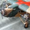
JWM Posted May 14, 2021 Author Share Posted May 14, 2021 (edited) I have faced the problem which I've heard something about but did not know it. Namely, both my boxes of Caproni Ca 101 has 7 cylinder engines, whereas the Caproni Ca 101 D2, for which the decals and schemes are provided in one of boxes was driven by Alfa Romeo D2 engines which was nine cylinder engine... This was cured in rebox of Fly model done by LF models https://www.1999.co.jp/eng/10585598. But I have original Fly kits. One option is do the Ca 101 bis, driven by 7 cylinders engines. The second option (I will try to go this way) is to do 9 cylinders engines ... Edit: I was wrong, there was another bag with 9 cylinders engines... Uffff..... This was Alfa Romeo D2 engine: Regards J-W Edited May 14, 2021 by JWM correction of mistake 2 Link to comment Share on other sites More sharing options...
Grandboof Posted May 15, 2021 Share Posted May 15, 2021 Inspiring work More types I was not aware of Martin H 1 Link to comment Share on other sites More sharing options...

Recommended Posts
Create an account or sign in to comment
You need to be a member in order to leave a comment
Create an account
Sign up for a new account in our community. It's easy!
Register a new accountSign in
Already have an account? Sign in here.
Sign In Now