ColonelKrypton Posted April 16, 2021 Share Posted April 16, 2021 (edited) After much scratching around I managed to stumble over a few interesting resin 1/72 scale kits of appealing subjects. My interests have always been out around the fringes of less common subjects and within that genre lay prototypes and experimental types of all nationalities. Of late my focus has been on British types as in my ongoing Gloster E.1/44 and during one of many internet trawls searching for reference material I stumbled across some eBay listings for several Olimp Master Resin 1/72 scale kits of the Fairey Delta FD.1, Boulton Paul P.111, and Boulton Paul P.120 all of which are interesting subjects. A deal was made and after a short while waiting on Canada Post I now have these kits in hand. After giving the kits a look over, it was decided to build the the Fairey FD.1 for this group build. These kits have been around for some time and reviews I found on line are a bit of mixed bag where some are quite favourable and others less so. My first impressions of these kits is bit of both. The larger main pieces are pretty nice, crisp molding, some flash, and very few noticeable pin holes. It is a different story for many of the smaller pieces that are in places noticeably rough some to the point of being nearly unusable. For example, the cockpit tub is a bit rough but can be cleaned up to make it acceptable but some of the parts will need extensive cleanup or replacement. In the later case one of the main wheels has voids and flash that make it unusable and the same goes for the pilots seat. I do have a plan for those less than acceptable parts. I have built better and far worse resin kits. This one will certainly not be "shake the box and everything falls together" build, it will be a lot easier going than my Gloster Nene Machine. Cheers, Graham Edited July 8, 2021 by GrahamCC update title 10 Link to comment Share on other sites More sharing options...
AdrianMF Posted April 17, 2021 Share Posted April 17, 2021 Looks like a pretty nice kit, and an interesting subject. If you can find a suitable distorting mirror you should be able to see an FD-2 in the reflection! Regards, Adrian 1 Link to comment Share on other sites More sharing options...
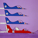
Mjwomack Posted April 17, 2021 Share Posted April 17, 2021 It doesn't look very aerodynamic, but there again nor's a bumble bee and that can fly so presumably this could or is the box just an artists interpretation? Link to comment Share on other sites More sharing options...
reini Posted April 17, 2021 Share Posted April 17, 2021 7 minutes ago, Mjwomack said: It doesn't look very aerodynamic, but there again nor's a bumble bee and that can fly so presumably this could or is the box just an artists interpretation? Reminds me of Lil' Draken (https://en.wikipedia.org/wiki/Saab_210) which was similar proof-of-concept aircraft. Small & stubby size definitely makes the planes look less aerodynamic even if that necessary wasn't the case? Interesting looking thing in any case! Wasn't there a full fledged version of this made too? Atleast to a prototype stage. 1 Link to comment Share on other sites More sharing options...
ColonelKrypton Posted April 17, 2021 Author Share Posted April 17, 2021 The box art is an artists drawing and quite good at that. The aircraft was built and flown with first flight in March 1951. Wikipedia is as a good reference as any : https://en.wikipedia.org/wiki/Fairey_Delta_1 The Boulton Paul P.111, P.111a, and P.120 delta's where similar in planform and size. The P.120 was lost in an accident. The P.111 went through several chances resulting in P.111a which still exists and is on display at the Midland Air Museum. They all had handling issues. cheers, Graham 1 1 Link to comment Share on other sites More sharing options...
Mjwomack Posted April 18, 2021 Share Posted April 18, 2021 10 hours ago, GrahamCC said: They all had handling issues. Another contender for greatest understatement award; nothing but respect for test pilots- walk out to that, take a look at it and think inherently unstable before announcing, yep I'll give it a go Link to comment Share on other sites More sharing options...
PeterB Posted April 18, 2021 Share Posted April 18, 2021 (edited) Hi, I have an old copy of Putnam's book on Fairey Aviation whjich has 6 pages on this plane - if you want me to look anything up just send me a PM, though Wiki is probably as good. Pete Edited April 18, 2021 by PeterB 2 Link to comment Share on other sites More sharing options...
ColonelKrypton Posted April 18, 2021 Author Share Posted April 18, 2021 5 hours ago, PeterB said: I have an old copy of Putnam's book on Fairey Aviation whjich has 6 pages on this plane - if you want me to look anything up just send me a PM, though Wiki is probably as good. Thank you kindly for the offer Pete. Wiki is good enough and I have managed to find a dozen and a half good reference photos and a 3 view. Every time I go trawling the net I seem to find another picture that I have not yet seen. cheers, Graham 1 Link to comment Share on other sites More sharing options...
ColonelKrypton Posted April 18, 2021 Author Share Posted April 18, 2021 Sunday SITREP on Fairey FD.1 ... I have managed to remove the casting blocks from the larger pieces and have cleaned up the fuselage pieces and cockpit tub and have a nice fit. I am waiting on some CA glue and micro tips before I can start any glue up of the parts however. Along the back edge of the cutting mat are the bits and pieces I have been casting over the past couple of days. Some generic WW1 type wheels in 1/48 scale, some generic MiG wheels in 1/72 scale and the new seat and wheels for the Fairey. Also done is the making of a couple of silicone molds of a seat and of the only good main wheel in the kit. The seat in the kit has a lot of excess resin and is quite rough. The seat I found to make a mold of is from the Boulton Paul P.120 kit and while a bit different is period correct and as when the canopy is place there will be very little to see the new seat will be OK. And for those so interested, I use Alumilite products as they are relatively easy to get and not too expensive. For the silicone mold I use Alumlite High Strength 3 and for resin the Alumilite RC-3 casting resin. The RC-3 casting resin mixes in a 1:1 ratio either by weight or volume. I use a small small and mix 6 to 7 grams of resin at a time and from that I can usually fill several molds hence the extra cast generic wheels. There are many different types of silicone mold material and casting resins all of which have their own pluses and minuses and some very expensive. These work for me. I don't have a pressure or vacuum pot so I do get some pin holes but I have found that if I use a syringe to "inject" the resin into mold so that the resin flows from bottom to top then I get a much better yield. The syringe if cleaned immediately can be reused a dozen times before needing replacement. cheers, Graham 2 Link to comment Share on other sites More sharing options...
PeterB Posted April 18, 2021 Share Posted April 18, 2021 (edited) I use something called Composi-Mold which can be melted in a microwave and reused many times over - they say 50 on the packaging, and to keep it cheap I use two part resin from a car parts shop. Providing I think it through before casting and get a sensible mould it works pretty well, and I too use a disposable syringe to "inject" which can be cleaned and reused with Methylated Spirits - I tried "proper" casting resing but it was expensive and no matter how carefully I measured the proportions and stirred, it took a week to set. The stuff I use is a third of the price and is set within 30 minutes, the only minor problem is that it is a bit thicker than the "proper" stuff so not as good for really small thin parts. The only thing you have to watch with the mould material is that you let it cool down until it is only just runny, otherwise it could melt the master - I put that in the freezer for a few minutes beforehand just to be safe! Pete Edited April 18, 2021 by PeterB Link to comment Share on other sites More sharing options...
ColonelKrypton Posted April 29, 2021 Author Share Posted April 29, 2021 The past dozen days or so has seen the continuation of cleaning up of the pour stubs on the resin pieces and careful test fitting of pieces together. But all was not without fraught. As I continued work at cleaning up the individual pieces it became clear that there seems as though some parts of the kit were cast in one type of resin and some in another. Very close in colour but texture is different; one is softer and more porous and grainy and the other a bit harder and far less porous and grainy. If you look closely at the picture of kit of parts you may see a slight difference in colour - the darker coloured parts are the ones that are a bit harder with a smoother overall texture. Whether the difference in resin is the result of different resin manufacture batches or pouring resin at different times under different conditions it is difficult to say. Some of the tertiary parts like the wheel well covers and other bits vary from useless to barely usable; I will have to make up some wheel well covers. It is almost like this kit is made up of leftovers or the worse parts from a couple of different kits and some of those other bits look like someone attempted to glue them back to pouring stubs for some reason. Overall my initial quite positive view of this kit is now somewhat diminished - I would give this example of the kit a solid 7 out of 10. Perhaps this is just a poor example of a very early kit, the pictures on the Olimp Pro-Resin web site for this kit show resin parts that look very well done. As well, each side of the fuselage are each of that "different" resin. After careful trimming and fitting it was clear that one side was a bit more than 1% larger than the other. This difference is not easily visible in the width of the fuselage but is very discernable in the height with one side being not quite a half mm larger than the other and about a mm too long. Easy to sand away and shape the top and bottom and extra length just caused a bit of head scratching and fussing to get it together. I have decided that I am not going to fuss over the cockpit interior. The cockpit tub was very rough and after some fussing I thought that I might just paint the inside of canopy black so that after the framing is painted the small open areas of the canopy will be a shiny black. The clear parts of the canopy are really quite small and it would be a challenge to look in and actually seem much of anything at this scale. In all it's current glory with thick primer applied for joint filling. I was stalled for a few days while waiting on some CA glue and while I was it I had also purchased some micro extension tips. These tips fit nicely over a variety of CA bottles and I also use them with the rubber squeeze bulb from an eye dropper to make a precision CA accelerator applicator. I can use this to apply a wee tiny drop or whiff of CA accelerator right where I want it with no mess. And while I was tinkering in the workshop I spent some time replacing scalpel blades. I keep my old dull blades in a Sharps Collector. These can be found on amazon and eBay and likely your local pharmacy and maybe if you ask nicely your doctors or dentist office may give you one. I used to dispose of old blades by wrapping up in a bit of paper towel or the like and putting in the trash but that seemed like such a waste. Now I can dispose of a full Sharps Collector and have it's contents properly recycled. If you don't want to or can't find one to buy you can use an empty disposable wipe container suitably marked. I keep my genuine Sharps Collector in the workshop and my substitute out in the shed. It takes many years to fill up one of these Containers. Next up plan to continue seem filling and smoothing and then make jig of some sort so that I can join the wings and fuselage. cheers, Graham 3 Link to comment Share on other sites More sharing options...
ColonelKrypton Posted May 1, 2021 Author Share Posted May 1, 2021 Fairey FD.1 Saturday SITREP ... Had some time to spend in the workshop today and got a little further on with the Fairey FD.1 After a couple of days of fussing I finally had a simple jig set up which was repeatable and not overly difficult to set up. Using my make do surface plate comprised of a 5/8" thick piece of glass, wings taped to a couple of 123 blocks and carefully aligned using a Starrett surface gauge, fuselage sat atop a piece of packing foam carefully shaped and shimmed with strategically placed card stock and using a Moore & Wright 5 inch square everything was carefully aligned, checked, re-checked, checked again, and then thin CA carefully applied so as to wick into and along the wing seems. Despite my carefully testing fitting and fussing when I removed the resin pouring stubs and wet sanding mating surfaces to what I thought were good fits, once everything was aligned in the jig and ready for CA it was obvious that I was off a bit but acceptable - filler goes a long way to make up the difference The surface gauge was used to ensure that the wings were level root to tip and that left wing was at same height relative to surface plate reference. It didn't matter if the wings were tilted up or down relative to the fuselage as the fuselage was adjust on its foam holder such that wings abutted the wing roots squarely. In an earlier post I mentioned that one fuselage side was about 1% larger than the other. On a fuselage 100mm long that amounts to 1mm. Well, the wing root on the left side of the fuselage is that same 1% larger than the wing root on the right side of the fuselage. That caused a bit of head scratching and fussing but I finally found an acceptable compromise in the alignment and allowed me to move onto the important step of adding CA. In the following picture you can just see the difference that the fuselage side that is 1% larger (mentioned in a previous post) that the other has. It appears as though the fuselage is a bit off square but it really isn't, it is a bit of an illusion because one fuselage is a bit bigger ( i.e. taller ) than the other and I have not yet been able to sand and shape the larger piece sufficiently to reduce that difference. The intake splitter ended up a little out of square too but that can be adjusted with a bit of sanding to make it look better. And finally, the vertical stabilizer is in place. And now it's starting to look like Fairey FD.1 cheers, Graham 2 Link to comment Share on other sites More sharing options...
AdrianMF Posted May 1, 2021 Share Posted May 1, 2021 Gosh that all looks like hard work! I’m surprised you are giving it as high as 7/10. Good solid jigging too. Looks like you are winning though, or at least currently ahead on points... Regards, Adrian Link to comment Share on other sites More sharing options...
matford Posted May 2, 2021 Share Posted May 2, 2021 On 4/17/2021 at 8:28 PM, Mjwomack said: or is the box just an artists interpretation? From the box top it looks like a Vickers Valiant and a DH Vampire had a puppy 1 Link to comment Share on other sites More sharing options...
trickyrich Posted May 8, 2021 Share Posted May 8, 2021 great and interesting choice for the build. I know these Pro-Resin models quite well, have built a few. They're not too bad and do require a bit of work but usually nothing so drastic. I like you wing setting device! Attaching wings and making sure they're level and even is always a pain with resin, plus for some reason they are always a tiny bit skew?? I like you casting work and the idea of using a syringe, will have to try and remember that. Bubbles are a pain, I don't have a vacuum box/chamber but have found using a pin to help remove bubbles once the resin is poured works quite well. Though my problem is that I use the fast curing resin so everything is rush rush. Link to comment Share on other sites More sharing options...
ColonelKrypton Posted May 10, 2021 Author Share Posted May 10, 2021 (edited) Monday SITREP. Work continues but at a leisurely pace. I managed to spend a handful of hours working on the Fairey this past week, small but important bits have been added, trimmed, broken off, re-attached and repaired along with seemingly endless pin hole filling. The surface of the resin parts are good but the fuselage side which was larger than the other ( right hand side ) when trimmed back to match the left revealed many tiny pin holes just lurking beneath the surface. My latest approach to tackling these pin holes as well as just general seam filling has been using Mr. Hobby's Mr. Dissolved Filler https://www.mr-hobby.com/en/product2/category_12/263.html applied with a dedicated size 0 or 1 brush. Small brush lets me put it right where I want it leaving minimal cleanup and you can also use the trick with a solvent wetted cotton bud to wipe over the area further smoothing the area before sanding. I also use regular Tamiya grey or white putty thinned with Tamiya extra thin cement to do the same thing and that does work too. Did you know that Tamiya Air Brush Cleaner is exactly the same thing as Taimya Extra Thin Cement with the green cap ( not the quick dry variety which also has a different green cap ) https://www.tamiya.de/en/accessories/tamiya-accessories/accessories/maintenance-material/tamiya-airbrush-cleaner-acryl-250ml-300087089/ This stuff works a treat at removing all sorts of tried on gunk form your airbush if you use one but can also be used to refill your bottle of Extra Thin Cement. On the picture you will notice some silver around the seam areas that I have been filling and fitting. I tried a couple of bottle of AK Interactive Xtreme metal paints but never really got on with it. This stuff is like Alcad and is more a very thin metallic lacquer than anything else. I struggled airbrushing it but I do find that I can brush it on small bits to add a bit of metallic sheen and it works very well to brush onto areas like seams and pin holes which I am attempting to file to show what further work needs to be done; dries quick , is very thin, and a silver colour really shows the defects. As an aside, AK have a many interesting "how to" articles on their web site; most are aimed at AFV modeling but you may find something interesting if you haven't looked recently https://ak-interactive.com/downloads One last tip. We all use abrasives of one sort or another, sand paper in one form or another is probably the most common. I have always used wet or dry in various grits, mostly wet. I have a repurposed margarine container on the workbench that is nearly always half full of fresh water; keeping the sand paper wet keeps it from filling sanding debris, cuts better, provides a better surface finish, and the paper lasts longer. A year ago I was in the local Canadian Tire store ( don't know what the equivalent would be in the UK - perhaps a cross between B&Q and Tescos ) and was poking around the automotive area where I noticed an interesting 3m product called "Super Flexible Sanding Sheets". A bit pricey ( don't be mislead by the Amazon prices in the provided link as Amazon prices are sometimes too much, in that case around 50% more ) https://www.amazon.ca/Super-Flexible-Sanding-Sheets-31852/dp/B07J25CMCK?th=1 This stuff is distinctly different from Tamiya sanding sponge, less than half the thickness with a rubbery feel to the yellow backing. I have been using for several months the same small strips of 400 and 800 grit I cut from one of the larger pieces . Used wet it cuts well now as when new. Folded over or around the edge of a piece of thin plastic card it works well for cleaning up small radiused fairings. On with a some more pin hole filling, a bit of cleaning up of panel lines and re-scribing, attaching small bits, and maybe the Fairey will be ready for it's first proper coat of primer later this week. cheers, Graham Edited May 10, 2021 by GrahamCC 2 Link to comment Share on other sites More sharing options...
ColonelKrypton Posted May 23, 2021 Author Share Posted May 23, 2021 Work continues on the Fairey but obviously at a slow pace. My workbench is a shared space for my model building and other interests. Having such a shared space means that I must from time to time clear off one project so that I can work on something else. I can be bit frustrating and a bit enthusiasm sapping. In any case, I cleared off a couple of other domestic tasks and found some time to work on the Fairey. References are generally important when we build something as we would like to get things as correct as possible. However, there is a balance between fussing too much and too little over the small details and having too much or too little reference material. Part of the pleasure is finding and studying some of those references. There is usually some easily found reference material for obscure subjects like this Fairey and I did manage to find a dozen or so good pictures. Like any prototype aircraft this one too was subject to changes and variations during it's life time. In addition to this Pro Resin kit there are at least two vac form kit ( Project-X 72 and Whirlykits ). All three are a bit different and each have somewhat varying details where all these details seem to be correct for different times within the lifespan of the original aircraft. I had to draw a line somewhere and decided to move forward building to depict the Fairey in the later part of it's lifespan. Initially the aircraft had very prominent leading edge slats on the outboard portion of the wings. The Pro Resin kit does not depict these and after trying and failing several different attempts to create them I chose to depict the later variation where they had been removed from the aircraft. However, there was a very obvious tail bumper visible ( lower part of the rear fuselage ) to guard against tail strikes in every photo that I had but none of the three kits showed this detail. As well, the anti spin parachute housing that was provided in the Pro Resin kit looked more like a rocket motor exhaust than a more simple cylinder that is seen in the photos. It is also seen in some photo's that what is described as an anti spin parachute in some texts was also used as a drag chute after landing. I had hoped to be ready for primer a week ago but all this little details sidetracked that plan. Tail bumper and anti spin parachute housing updated more to follow ... 1 Link to comment Share on other sites More sharing options...
ColonelKrypton Posted May 23, 2021 Author Share Posted May 23, 2021 39 minutes ago, GrahamCC said: but none of the three kits showed this detail. I made a mistake in this statement - both of the vac form kits show the tail bumper on their drawing but I am not familiar enough with the kits to say how this detail is included and as for the Olimp Pro Resin kit, the box top drawing shows the bumper but it is not included on either of fuselage halves nor is there a wee tiny bit of resin included that could be use for this detail. I added the bumper to my build using a bit of scrap plastic fixed in place with CA. On the end of each wing is a pod and probe. I have not found much information on just what the purpose of these were but presumably they were some type of instrumentation. The kits provides two roundy pointy thingys to use as part of this structure but the are small and the wing tips thin. First instinct was to just try gluing one in place to see how that works out - it didn't as it was quickly knocked off. Used a 0.5mm brass pin. Drilling a hole in the roundy pointy thingy was easy but a bit of challenge to get it in the center. Drilling a 0.5mm hole in the wing tip which is not quite 1.5mm thick was a bit more of challenge. A bit of careful work using a 0.5mm carbide PCB drill and a pin vise and I managed to get the job done. I have and used the very common wire size number twist drills for many years but of late I have been using the carbide PCB drills easily found on eBay and Amazon. They are brittle but sharp and work very nicely on resin and styrene. Still, they do require a more gentle touch than the carbon steel number twist drills, both types have their place. Speaking of pin vises, we generally all have at least one, sometimes several. The best holder I have found for these carbide PCB drills is not really pin vise, it is in fact the body of a Starrett scriber having the 1/4" size body. If you remove the scriber point you will find that the tail end of the scribers is 1/8" diameter and these carbide PCB drills fit very nicely and securely. The size of the scriber body provides for a very nice feel when using the drills. It is also very handy to use with 1/8" shank carbide die grinder bits as well. The scriber / pin vise is in the center of the following photo. Also of note is my other favourite pin vise which really isn't a pin vise in the traditional sense. It is an Albrecht C30-J0 0-3mm chuck mounted on a JT0 to 1/2" arbor. It is weighty enough that I often just chuck up a drill and use the weight of the thing to provide enough pressure to do the job while I gently turn it. more to follow ... Link to comment Share on other sites More sharing options...
ColonelKrypton Posted May 23, 2021 Author Share Posted May 23, 2021 Worked continued with the fixing in place of the tiny horizontal stabilizer on top of the vertical fin. This was the easiest bit done this past week. Also added where the long wing tip probes made from 0.5mm brass rod. A bit more fussy work with that 0.5mm carbide PCB drill into a very thin leading edge. A tip for using CA glues. As you know, these seem to get everywhere - on your fingers, on bits adjacent to where you are trying to affix something, etc. CA debonder works very well at cleaning up these oops. Acetone can be used but I found purpose made products do seem to work the best. When affixing the small horizontal stab on top of the fin I used a tiny drop of thick CA to get it in place and then finished the seem with thin CA applied with a micro tip on the CA bottle. This generally went well but I did make a bit of mess which was quickly cleaned up with the CA debonder. Also, a common practice with common modeling putties is to put the putty on and then running over the seam using a cotton bud dipped in thinner to smooth out the putty and remove the excess. You can use this same technique with CA and CA debonder. Wait till the CA kicks off using either patience or CA accelerator and then use a cotton bud soaked with debonder to go back over the seam to clean up any excess and to smooth it over. It will not soften all the CA through the joint unless you flood the area and let the cotton bud linger or rub too hard. As well, I have the landing gear legs in place. The main gear took quite a bit of fussing to get in place. There are gear wells that were separate pieces which needed fitting in each fuselage half. Inside each wheel well was a hole in a bit of a block into which the legs where to be glued. However, the small difference in size of each of the fuselage halves and each wheel well needing to be fitted and glued in separately meant that even with each gear leg the same length the result was an airframe which did not sit level. After much trimming, fussing, cussing and a careful application of eye ball surveying I got them lined up so that the airframe sits (mostly) level and the legs (mostly) properly aligned left to right and fore to aft. After all that fussing they are off a bit but you have to look real close. You can just see the left side gear leg in the follow photo. You may have noticed in the preceding photos patches of shiny metal bits. I have been experimenting with using aluminum duct tape ( the kind made from real aluminum foil ) and kitchen foil to create small panels and fittings in order to add a bit of dimension to models. This tape is quite thin but truly quite thick in scale. However, after application and a gentle sanding with 400 and 600 grit wet or dry they do thin out especially around the edges and I am hoping after the application of primer they will provide a quite acceptable look. Kitchen foil is thinner than the aluminum duct tape but the advantage of the aluminum duct tape is that it already has an adhesive backing. Bare Metal Foil would also work but it is perhaps a bit too thin for the effect I trying to get. Left to do on the landing gear is to add the remaining piece of the front landing gear ( don't know what to call it - knuckle or oleo strut or ?? ). This bit and the similar bits for the main gear are provided as somewhat recognizable lumps of resin. Resin is a good material for model making but for these tiny complex pieces it just doesn't seem to be the right choice. I have already tried cleaning them up but they are too delicate, and too brittle and soft at the same time. I think I am going to have to carve something out of brass or plastic as I have been unable to find anything suitable in the spare parts bin. Also the canopy. The vac formed canopy is OK but a bit thin and distorted. I am still planning on painting the inside black and not doing up the cockpit details. The clear window portion of the canopy would not let you see much of the cockpit anyway. Maybe I will try my hand at making a master using the provided vac form canopy and vac form my own. In any case this is some more fussing detail work yet to be done. It will take some time to fuss over these last bits but maybe, just maybe I will be able to prime by next weekend cheers, Graham 3 Link to comment Share on other sites More sharing options...
Mjwomack Posted May 23, 2021 Share Posted May 23, 2021 This is a Wonderfull build, I like the tip about aluminium tape- I've got a load lying around and can feel some practice coming on. Link to comment Share on other sites More sharing options...
PeterB Posted May 25, 2021 Share Posted May 25, 2021 (edited) FYI the "V" shaped bits are usually referred to a scissors - they open and close as the oleo strut in the leg extends and retracts AFAIK. Pete Edited May 25, 2021 by PeterB Link to comment Share on other sites More sharing options...
ColonelKrypton Posted June 5, 2021 Author Share Posted June 5, 2021 Another short update ... Progress is slow getting the last little bits done up before paint. As previously described, some of the resin cast bits in this kit are less than useable. The scissors ( thank you Pete ), the nosewheel gear, gear doors, and a few others. I spent some time fussing what to do with the nosewheel gear. A couple of attempts of carving scrap plastic and brass bits to shape resulted in some nice pieces but nothing close to what I wanted as they all just didn't right. Stepping back and taking a closer look at a couple of pictures and then glancing back down on the workbench and something suitable was spied. I have a Frog / Novo bagged kit of the Hawker Sea Hawk off to the side of the workbench waiting to start assembly for the "Less than a Tenner group build" and there is was in all it's flashy oversize glory were the two pieces that make up the nosewheel gear of the Sea Hawk. Suitably seconded from the Sea Hawk and carefully glued together sans nose wheel, and an hour or so of fettling with files and micro saw a suitable piece emerged for the Fairey Delta. In the photo you will see the raw Sea Hawk nose gear and beside it the brittle lump of resin from the kit. Even the piece from the kit is not really the correct shape but I did try to clean it up and was not surprised that it very quickly started to crumble as the clean up progressed. The nose wheel was salvageable from it's resin casting block but was initially a bit rough. Some delicate sanding cleaned it up to a suitable form. Nose wheel gear in shape, nose wheel fitted using a piece of Albion Metals tube for an it's axle, and nose gear cover made from a piece of sheet plastic and mounted in place. Main gear wheels in place and canopy mounted. Mounting the canopy, what a treat that was. The kit included two vac formed canopies. One was unusable from the start and other not too. It was the not too bad one that ended up mounted on the Fairey but not after I made an attempt of making a few more as an exercise in making something better. Non of the ones I made were any better so I just used the original. Biggest trouble with canopy is that the frame detail is soft and indistinct. The glass area of the canopy is quite small and given the issues earlier in the build of the two fuselage sides being somewhat different in size by about 1% resulting in a cockpit area which was not square, the decision was made to paint the inside of the canopy black and mask off the glass area on the outside before painting. There would have been very little to be seen through the tiny bits of glass in any case. After a half dozen attempts the canopy is in place and now that I look at it in the picture the whole canopy appears to be a bit on the large side, a bit too tall. Perhaps just a result of the black in the image and it will look better once painting it done. Getting closer. Waiting masking on the canopy, a final dusting, then primer ... cheers, Graham 4 Link to comment Share on other sites More sharing options...
ColonelKrypton Posted June 23, 2021 Author Share Posted June 23, 2021 Good day all, The end of this group build is fast approaching and I am still puttering along at snails pace; too many other things on the go. I recently got a couple of new items that I hoping will make model building a wee bit easier. My old and well used Tamiya painting stand had seen better days so I bid it farewell a couple of months ago. I thought I could manage without but I came to miss the old the thing but opportunity came knocking and I now have something to replace it. The Tamiya painting standing is nice bit of kit made of plastic with handy holes used to hold clips and what not. My replacement however is a bit more substantial and will likely last a very long time. It is about an inch larger in diameter and made from cast iron. I wasn't sure about the rotating top piece but a magnet reveals that it is indeed ferrous. Smooth easy turning bearing and the top piece rotates flat to within about half a mm. I fully expect as needs arise that I will be drilling and tapping holes in the top piece to hold jigs and what not. It was about half as much again as the cost of a new Tamiya paint stand but after using it for a few days I think it is a fitting replacement. I found it on Amazon and it is called a sculptors wheel or a banding wheel. Made to hold and support much more weight than a typical model and if a 7 inch surface is not large enough then there are also 12 inch ones too. The other piece of kit that recently found it's way to my workshop is sitting on top of the wheel. Called a vortex mixer and is also an Amazon purchase. If you search you will find others. One of the more common goes by the brand name of Intllab and is of a differing design than this one. If you look carefully at the specs you will find that the less expensive ones typically have a 7.5W motor whereas ones like this have a 12W motor. To my thinking and from comments on youtube the 7.5W style seems a bit underpowered. The particular one I choose is sold under the brand name "Lab Fish". I like it and I hope it will help relieve most of the wrist straining chose of mixing and shaking up paints. So, just where am I a with the Fairey Delta 1 build? Primer is on and just today I tried to apply the first coat of bare metal paint. My choice of paint is the Mission Models Paint line and first coat is to be their Duralunimum which is darkish shade to be followed a light dusting of their white aluminum. The goal is try and create a bit of depth the finish. Well, best laid plans of mice and men and all that, my plan didn't go as expected. I got a bit over enthusiastic with the airbrush, made a bit mis adjustment of the needle in fact, and ended up far too quickly applying a bit too much paint. The picture doesn't show it very well but what I did apply is a bit grainy and ran a bit. It will need a bit of attention with some wet or dry before I continue. Also, I primed with Tamiya rattle can grey primer which went on well BUT I should have used white primer as there is just too little of a difference in colour between the grey primer and Duraluminum that it contributed to my painting mistake. Just goes to show that it never pays to try and rush. It will need a day or so to properly cure before I can rub it down a bit before continuing. Will I be able to finish in time for the end of the group build? Will I be able to impose my will on sorting out and finishing the paint work? Stay tuned, same Bat time, same Bat channel ... cheers, Graham 1 1 Link to comment Share on other sites More sharing options...
Mjwomack Posted June 24, 2021 Share Posted June 24, 2021 That is so very frustrating. I'm sure you can pull it around yet though. It definitely makes me think of a silver bumble bee (I'm not sure they exist so I don't suppose it can remind me of one). On the bright side, you get to use the new turntable again; just seems an arduous way to justify that! Link to comment Share on other sites More sharing options...
Mjwomack Posted June 27, 2021 Share Posted June 27, 2021 I hope this is being salvaged; in a rare moment of look and learn I realise I'm heading for a similar peril with the build I'm doing in the Unarmed GB where I was going to have a grey going over grey primer that was a very close match and I'd struggle to see what was going on. Im going to use an intermediate coat of white primer. So, seriously thanks for sharing the setback as I've learnt from it. 1 Link to comment Share on other sites More sharing options...

Recommended Posts
Create an account or sign in to comment
You need to be a member in order to leave a comment
Create an account
Sign up for a new account in our community. It's easy!
Register a new accountSign in
Already have an account? Sign in here.
Sign In Now