giemme Posted April 20, 2021 Share Posted April 20, 2021 37 minutes ago, Fritag said: Well success in principle. Success in practice depends on how well I manage to recreate the various ribs and stringers and gubbins. It does look good already, though Ciao Link to comment Share on other sites More sharing options...
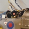
Troy Smith Posted April 20, 2021 Share Posted April 20, 2021 22 hours ago, Fritag said: I’d like ideally to do something about the fat slab-sided nose - not so worried about the wing chord and fuselage length as I don’t think they’re so noticeable to the non-expert. The wing chord is really easy. The slab side nose can be done in isolation, and should not affect the cockpit work, as can be seen below, requires cutting the wing root and into the flat of the Tamiya nose, and then just bending the plastic in and up I found, you need to overbend to get it to hold the right shape, but that's it in this you can see what I mean about overbend, note how the plastic is curved up, I may have use some fine pliers to do this this may affect the nose under panel, but I think that again is a V saw cut and some bending. Really though, I'm not sure how clear my original post was, the Tamiya kit is too slab side in the nose and behind the cockpit. You sidewalls show what is not always understood (certainly in kits, I think the first Spitfire kit with the sidewalls was the 1/48th Hasegawa VB) up until then they went into the flare out from moulding the wing fillets this is a rare shot with the fillest removed, which shows the true fuselage shape Spitfire boneyard. by Etienne du Plessis, on Flickr Unfortunately my pics of the Hendon Mk.I in a similar state are not very good... the colour pic above is from here @Etiennedup fantastic Flickr of period colour images, the link is all the Spitfires, lots of great shots for really getting a feel of the airframe, note the aluminium paint behind the seat in this one (PS edit , which is a Vb BTW) Spitfire Mk.V cockpit. by Etienne du Plessis, on Flickr and then have a look here http://spitfiresite.com/2010/07/anatomy-of-spitfire-cockpit.html "The aircraft serving as our subject is Supermarine Spitfire Mk. Vb BL628 YO-D, recently completed by Avspecs Ltd in Auckland, New Zealand. Due to the fantastic quality of the restoration work which took full 30 years, the cockpit of this Spitfire conforms almost entirely to wartime production standards. For this reason, the following photographs can serve as reliable reference to the cockpit layout of the production Spitfire Mk. V." Basically, apart from the cockpit to seat bulkhead, and engine bearers, all the rest of the internals are aluminium paint, gun bays, inside of wheel well, but the external wheel part is underside colour. as shown in this screen grab of the Spitfire daily inspections films Spitfire Mk.I maintenance film UC well colour by losethekibble, on Flickr see here, and note there are 5 films in total (note bar underneath main image) https://www.iwm.org.uk/collections/item/object/1060020636 "Instructional film with voice-over for groundcrews of the routine inspection procedures to be followed on a Supermarine Spitfire Mk I. Filmed at RAF Northolt during the early summer of 1940. Spitfires featured are 609 Squadron aircraft." which you may find of interest as a IIRC you are/were a pilot? Again, great for getting a feel for the airframe. cheers T 7 Link to comment Share on other sites More sharing options...
CedB Posted April 21, 2021 Share Posted April 21, 2021 Nice progress Steve and, with Troy's input, I think we're going to have a great model here. No doubt 1 Link to comment Share on other sites More sharing options...
Fritag Posted April 22, 2021 Author Share Posted April 22, 2021 (edited) On 4/20/2021 at 10:52 PM, Troy Smith said: @Etiennedup fantastic Flickr of period colour images, the link is all the Spitfires, lots of great shots for really getting a feel of the airframe Couldn’t agree more. Some fabulous images This one took my eye because, whilst it’s listed as being a Mark Vc - and in any event it has the internal armoured windscreen - it looks to me like it has the old flat sided hood. Just goes to show that all sorts of combinations must hve ended up together in the field. On 4/20/2021 at 10:52 PM, Troy Smith said: and then have a look here http://spitfiresite.com/2010/07/anatomy-of-spitfire-cockpit.html I picked up on those photo’s of BL628 from the link you posted on Stix’s thread - invaluable thanks So whilst I ponder whether to risk trying to do something with the overweight yet flat sided nose - and thinking I probably won’t on this one - I’ve done a bit more with the cockpit. Having removed the cockpit door I had a go at adding some detail to the opening. Fiddly little scribing job: And some thin strip added all around the edges as the opening on the full size one has a thin flange (or whatever it’s called) around it. A little touch that should stand out with dry brushing and add a bit of interest. And I’ve added most of the structure to the cockpit - now need to add the equipment. it is curiously difficult to create a thin strip with evenly spaced holes in it, as was needed for the the middle vertical piece of framework. Much swearing was involved. More this weekend hopefully. Edited April 22, 2021 by Fritag 16 Link to comment Share on other sites More sharing options...
hendie Posted April 22, 2021 Share Posted April 22, 2021 Curiously difficult? Or downright impossible? I generally drill all the holes by lining my drill bit against the side of a ruler to try and get something approaching straight to begin with. Only then do I cut the strip down to the width I need. I usually get something acceptable after 7 or 8 attempts 1 6 Link to comment Share on other sites More sharing options...
Fritag Posted April 22, 2021 Author Share Posted April 22, 2021 3 minutes ago, hendie said: I generally drill all the holes by lining my drill bit against the side of a ruler to try and get something approaching straight to begin with. Only then do I cut the strip down to the width I need. I usually get something acceptable after 7 or 8 attempts Ditto - including the number of attempts...... 4 Link to comment Share on other sites More sharing options...
Navy Bird Posted April 22, 2021 Share Posted April 22, 2021 I like the flange. Flanges are good. 👍 Cheers, Bill 4 2 Link to comment Share on other sites More sharing options...
giemme Posted April 23, 2021 Share Posted April 23, 2021 7 hours ago, hendie said: Curiously difficult? Or downright impossible? I generally drill all the holes by lining my drill bit against the side of a ruler to try and get something approaching straight to begin with. Only then do I cut the strip down to the width I need. I usually get something acceptable after 7 or 8 attempts Ditto #2. With the variant that I use Tamiya masking sheet instead of a ruler, since it has a millimeter square pattern printed on it. Still lots of swearing, though. Top detailing job, Steve! Ciao 2 Link to comment Share on other sites More sharing options...
Terry1954 Posted April 23, 2021 Share Posted April 23, 2021 Lovely internals, especially those flanges! Terry 1 Link to comment Share on other sites More sharing options...
Fritag Posted April 23, 2021 Author Share Posted April 23, 2021 (edited) 8 hours ago, hendie said: I generally drill all the holes by lining my drill bit against the side of a ruler to try and get something approaching straight to begin with 43 minutes ago, giemme said: Ditto #2. With the variant that I use Tamiya masking sheet instead of a ruler, since it has a millimeter square pattern printed on it. I have a clever ruler with holes in it Can’t remember where I got it, I’ve had it that long: It’s principal use is to mark-out accurate measurements on plastic card etc. with pencil dots or pinpricks. But It made getting the holes in a straight line bit tolerably straightforward - The bit I had trouble with was then cutting and sanding sufficiently neat narrow strip around the ‘oles..... Edited April 23, 2021 by Fritag 11 1 Link to comment Share on other sites More sharing options...
giemme Posted April 23, 2021 Share Posted April 23, 2021 8 minutes ago, Fritag said: The bit I had trouble with was then cutting and sanding sufficiently neat narrow strip around the ‘oles..... If only you had a Silhouette cutter.... Ciao 3 Link to comment Share on other sites More sharing options...
Biggles87 Posted April 23, 2021 Share Posted April 23, 2021 Oops, late again, must look at the WIP page more frequently. I like your plan for the cockpit sidewalls, I used a similar method on my Tamiya Spitfires long ago. If you haven’t already looked, the Spitfire Site has an excellent Mk V cockpit ‘ walk around ‘ which you might find useful. I’ll go back to the beginning now and read it properly. Stay safe. John Link to comment Share on other sites More sharing options...
Troy Smith Posted April 23, 2021 Share Posted April 23, 2021 11 hours ago, Fritag said: This one took my eye because, whilst it’s listed as being a Mark Vc - and in any event it has the internal armoured windscreen - it looks to me like it has the old flat sided hood. Just goes to show that all sorts of combinations must hve ended up together in the field. Hmm, I'd not always trust the captions, the image you mention is a close up of this, note the chap in the cockpit in the one you posted has a US flying helmet and goggles Spitfire-AA963 in the U.S.A. by Etienne du Plessis, on Flickr I can't remember the full details, I think the hood with the blown sides maybe later, as this is a very early Vc @gingerbob is a good chap for these details. Anyway, all credit to @Etiennedup for collating and hosting these images. There is so much detail to be seen in these I usually spot somehting new each time. neat progress on the cockpit too. 3 Link to comment Share on other sites More sharing options...
CedB Posted April 23, 2021 Share Posted April 23, 2021 Nice work on the internals Steve, especially that flange Must get one of the holey rulers… oooh, lots of them on Amazon… HOW MUCH!! Precision tools, an investment… 1 5 Link to comment Share on other sites More sharing options...
Terry1954 Posted April 23, 2021 Share Posted April 23, 2021 54 minutes ago, CedB said: Nice work on the internals Steve, especially that flange Must get one of the holey rulers… oooh, lots of them on Amazon… HOW MUCH!! Precision tools, an investment… I agree that's an excellent tool. That specific one looks quite pricey as you say, but google on "High Precision Scale Ruler T-type Hole Ruler Carpenter DIY Measuring Tool Set", for cheaper versions. Certainly a similar type of thing I think. Terry Link to comment Share on other sites More sharing options...
Ex-FAAWAFU Posted April 23, 2021 Share Posted April 23, 2021 On 4/17/2021 at 7:08 PM, Navy Bird said: Hasegawa Hubris Was that the IJN equivalent of the Fairey Fruitbat? 5 Link to comment Share on other sites More sharing options...
Fritag Posted April 23, 2021 Author Share Posted April 23, 2021 46 minutes ago, Ex-FAAWAFU said: Was that the IJN equivalent of the Fairey Fruitbat? Perhaps - but probably not as corporeal as the Hughes Hercules. 4 Link to comment Share on other sites More sharing options...
CedB Posted April 25, 2021 Share Posted April 25, 2021 On 23/04/2021 at 11:18, Terry1954 said: I agree that's an excellent tool. That specific one looks quite pricey as you say, but google on "High Precision Scale Ruler T-type Hole Ruler Carpenter DIY Measuring Tool Set", for cheaper versions. Certainly a similar type of thing I think. Terry Thanks Terry - £10 shipped? Ordered! Now I just have to wait… and hope the Suez canal doesn't get blocked again. 4 Link to comment Share on other sites More sharing options...
Fritag Posted April 25, 2021 Author Share Posted April 25, 2021 In between cycling, gardening and looking for new car a bit of modelling got done. Everybody drills out the lightening holes in the frames as far as I can see - so I thought I’d better follow suit. Before: After: Rather surprisingly no carbide drill bits were harmed in the making of this production... One of the consequences of not using the Aires resin side panels in the build - principally because of the thickness they add to the fuselage sides - is that the Aires instrument panel and seat frame are now undersized for cockpit and can’t be used. So it’s a matter of modifying the kit parts. Instrument panel: The lower section needs to be cut away so the top section will fit with the resin fuselage floor: And the IP needed sanding flat ready for a photo etch panel. The Aires resin IP is on the right, and I’ll probably pinch the compass and gunsight and use them on the kit IP. The most work went on the seat support frame. The Aires frame on the right is there to show how much needs to be cut off the bottom to fit with the resin floor: And this one shows how crude the seat support structure is with the kit moulding (and more lightening holes to drill out); So with some cutting, fettling and drilling of the kit frame plus some plastic rod and strip and the head armour from and Eduard set - we get this: Which is mostly pointless as it will be covered by the seat and armour Hey ho..... And a quick test fit on the cockpit floor: Back to the cockpit sidewalls next...... 19 Link to comment Share on other sites More sharing options...
giemme Posted April 25, 2021 Share Posted April 25, 2021 This is looking a bit good, Steve Ciao 1 Link to comment Share on other sites More sharing options...
CedB Posted April 26, 2021 Share Posted April 26, 2021 Seconded! A seat for a king 1 Link to comment Share on other sites More sharing options...
Brandy Posted April 26, 2021 Share Posted April 26, 2021 With a little tweaking those extras are mating up nicely with the kit bits. Looking good! Ian 1 Link to comment Share on other sites More sharing options...
TheBaron Posted April 26, 2021 Share Posted April 26, 2021 Excellent aeronautical orthodontistry and sundry drill thrills Steve; I'm abysmal at drilling lines of holes like that so very admiring of your results. That little hand vice looks just le billet there for steadying delicate piecework - can you remember where you got it from dear heart? Good luck also with the car hunt. 1 Link to comment Share on other sites More sharing options...
hendie Posted April 26, 2021 Share Posted April 26, 2021 16 hours ago, Fritag said: Which is mostly pointless as it will be covered by the seat and armour ah... I see you are getting back into the ways of the modeler's ethos then Lovely work on that seat support structure Steve. 2 Link to comment Share on other sites More sharing options...
Fritag Posted April 26, 2021 Author Share Posted April 26, 2021 (edited) 11 hours ago, TheBaron said: That little hand vice looks just le billet there for steadying delicate piecework - can you remember where you got it from dear heart? It is just the ticéad for making neat and precise cuts at 90 degrees and 45 degrees on small structures and tube and rods. And for holding small stuff. I got it on evil bay in September 2017. I remember I saw such a thing on the Uschi Van der Rosten site (not listed there any more) and thought it'd be useful but not at that price. Bit like @CedB and the precision ruler (above).... Anyways I found a lower grade cheap version on ebay - something like this probably: Ebay - Jig Vice Mitre Cutter and I remember having to spend some time cleaning and polishing it to get rid of the machine oil etc that tends to cover cheap tools. As ever you get variable quality variable cost versions. Moving on.... In my attic I have an old cupboard where there reside some modelling bits and bobs I've had since I was a kid. Amongst them was an envelope of plans I had as a teenager; mostly for flying models (electric round-the-pole and free-flight) but also scale plans I bought. I dimly remembered having some spitfire plans and when I had a look I found some 1/72, 1/48 and 1/24 plans for various marks, including the Mk 1, drawn by G. A. G. Cox and M. J. Lee. Now, I've no idea of the accuracy of these plans, just like I've no idea of the accuracy of the Jumpei Temma plans I referred to earlier. But one should never let mere ignorance stop one from blundering on should one? And so: The kit fuselage laid over the Jumpei Temma plans - aligned at the cockpit door - shows the kit to be a tad (just under a mm) short at the tail and also at the the nose (you'll have to trust me as to the nose as it's masked by the parallax error). The overall length discrepancy is to the Mk 1 eyeball the 1.5-1.6 mm shortfall others have identified. Laid over the Cox & Lee plans the length and shape is spot one (again you'll have to trust me on the nose due to parallax). I therefore like these plans..... But if the kit is too short then there must necessarily be a small drafting or copying error in the plan.... In both cases the wing front and rear line up well with the plans. As to the wings. Both do show the wing chord being too wide. Jumpei Temma - but not by much - and there are also some subtle shape differences discernible. Cox & Lee - quite a bit more -and probably more like the amount that others have identified. Where does this take me? Nowhere really. Just did it for (all our) amusement and interest (I am in this, as ever, your humble and obedient servant). I'll defer to the expert knowledge of @Troy Smith and others, who have put some proper thought and research into this. What I found potentially more helpful was the profiles on Jumpei Temma's plans. Troy has spoken of the 'slab-sided' as well as fat nature of the Tamiya nose and I think this can be seen here. Taking Jumpei Temma's profile at 30" and cutting it out seems to bear out that not only is the nose a bit wide - it doesn't quite capture the curve on the top or sides of the cowling. Again - I'm not assuming that the plans are accurate but they are consistent with Troy's anaysis. What I think I can say is that to correct it fully would involve subtly recontouring the top and sides of the cowling as well as thinning the fuselage. This extra work is just the excuse I was looking for not to probably means I won't incorporate any modifications in this build I have therefore prepared my excuses case as follows: (1) there is a small but significant risk of failure and ruining the build in attempting the modifications (2) the kit was given to me by Jim at the 453rd BG museum for eventual display (3) It would be unreasonable to risk Jim's kit when his casual visitors will not know or care about the subtle errors. There how was that? Persuasive? Back to the build. Tiny update done to avoid doing any real-life work..... There is some structure behind the frame at the back of the canopy - which (I guess) supports the radio mast and the sutton harness wires also go on further back that first frame. This photo is from The Spitfire Site which Troy mentioned above. I won't go overboard - but the horizontal 'X' shaped structure will probably be a bit visible through the kit canopy if not much or anything else. The obvious thing to do was to make a copy of the frame I already had using plasticine and casting resin - thus: And I'll use one of them for the next most rearward frame and see if I can make a horizontal 'X' frame out of spares. Shan't bother to drill out the lightning holes this time...... Edited April 26, 2021 by Fritag 12 1 Link to comment Share on other sites More sharing options...

Recommended Posts
Create an account or sign in to comment
You need to be a member in order to leave a comment
Create an account
Sign up for a new account in our community. It's easy!
Register a new accountSign in
Already have an account? Sign in here.
Sign In Now