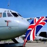
Pete in a shed Posted April 1, 2021 Share Posted April 1, 2021 Hello all, I’ve decided to have a go at another large Russian aircraft as that is my passion and thought I’d post it as a work in progress. The Il-38 has undergone an upgrade which added the new sensor array (BERKUT) (NOVELLA) atop the fuselage, new avionics and all topped off with a new colour scheme. The overall colour seems to be Aubergine/French blue/ USN WW2 dark blue cross, don’t know how that’s going to pan out. The photo shows the aircraft I will try to model. The Amodel kit comes with the fuselage and main wings moulded in glass fibre, the rest in (short run) plastic. A few weeks ago I bought the new Begemot decal sheet that includes the Russian wording seen on the tail and the big yellow numbers for the front. I also have the Begemot sheet that has the modern 2 tone stars I will need as the ones in the kit are the old style ones. I still have to source a flag and will have to make the name in red myself. Where needed, smaller parts will be replaced with etch parts. So, off we go. The inspiration The box of many parts. First job was to cut the unwanted glass fibre from the fuselage front where the cockpit will go, clean up the bomb bays and drill out the windows using my Dremel tool. I had a bit of trouble with the forward windows in that the glass fibre splintered making a jagged hole. To get round this I stuck the kit plastic windows in the jagged holes and filled around them with Milliput. The whole lot was then sanded down, finishing with fine grade micro mesh to make the windows transparent again. Front end and bomb bays cut and cleaned. Windows filled and sanded. While waiting for the Milliput to dry around the windows I assembled the bomb bays. As usual with these kits the plastic parts need cleaning up with a scalpel blade and glass paper to ensure a good fit. These subassemblies are boxes that fit into the slots in the bottom of the fuselage shown above. Cockpit next I think. 14 Link to comment Share on other sites More sharing options...
billn53 Posted April 1, 2021 Share Posted April 1, 2021 Hmmmm... I’m not seeing your pics. That’s a shame, because this sounds quite interesting. Link to comment Share on other sites More sharing options...
k5054nz Posted April 1, 2021 Share Posted April 1, 2021 I hadn't realised how far forward the main undercarriage is - it's insane! I actually winced when I saw how much of the aircraft was aft of the wheels!! AMonster kits are fascinating to me (the Hughes H-4 is a dream build for me) and I'm excited to follow along with your build. Link to comment Share on other sites More sharing options...
Pete in a shed Posted April 2, 2021 Author Share Posted April 2, 2021 9 hours ago, k5054nz said: I hadn't realised how far forward the main undercarriage is - it's insane! I actually winced when I saw how much of the aircraft was aft of the wheels!! AMonster kits are fascinating to me (the Hughes H-4 is a dream build for me) and I'm excited to follow along with your build Hello Zac Yes, how the thing doesn't sit on its rear end is a bit of a mystery 🤔. I think I'm going to have to raid the local church roof in order to get enough lead to stop the model from becoming a tail sitter. have you got the Hughes in your stash? 10 hours ago, billn53 said: Hmmmm... I’m not seeing your pics. That’s a shame, because this sounds quite interesting. Hi, not sure why that is, I've re posted them, see if that makes a difference. 2 Link to comment Share on other sites More sharing options...
billn53 Posted April 2, 2021 Share Posted April 2, 2021 3 minutes ago, Pete in a shed said: Hmmmm... I’m not seeing your pics. That’s a shame, because this sounds quite interesting. Hi, not sure why that is, I've re posted them, see if that makes a difference. Thank you, looking good now. Link to comment Share on other sites More sharing options...
Flankerman Posted April 2, 2021 Share Posted April 2, 2021 The Il-38 is based on the Il-18 airliner - with the wings moved forward 3m (9ft) for CG reasons - because of all the mission equipment fitted. I built mine 17 (!) years ago..... :- http://www.flankers-site.co.uk/modl_il-38.html I fitted a lot of weight into the forward fuselage (a spark plug and a heavy bolt)..... ....but I still had to fit a tail prop support (as on the real thing).... One major problem I found is that the canopy sill on the fuselage moulding is not parallel to the ground.... (either that or the wings aren't fitted correctly?) ... I had to add plastic card to the lower (stbd) side and sand down the highr (port) side to make the canopy fit correctly... Check yours out before proceeding much further. Great progress so far BTW - yours is looking great. Ken PS _ I have just realised looking at your pics - mine didn't come with weapons bay interiors - just the doors - the interiors must have been add in later kits (?) 7 Link to comment Share on other sites More sharing options...
roginoz Posted April 2, 2021 Share Posted April 2, 2021 Wow ! Gonna be following your build, @Pete in a shed, always interested in big Russians ! Just checked my decals stash and i reckon I can supply the blue and white flags, if these are the ones you mean. Good luck with the build. Rog Yep, found 'em. PM me if you can't find them locally. 1 Link to comment Share on other sites More sharing options...
Marklo Posted April 2, 2021 Share Posted April 2, 2021 (edited) Nice build. I’d add weights to the engine nacelles and the wing leading edges too. I had to do this in my TA154 to prevent it tail sitting. Edited April 2, 2021 by Marklo 1 Link to comment Share on other sites More sharing options...
Pete in a shed Posted April 2, 2021 Author Share Posted April 2, 2021 1 hour ago, Flankerman said: PS _ I have just realised looking at your pics - mine didn't come with weapons bay interiors - just the doors - the interiors must have been add in later kits (?) Hello Ken, thanks for the heads up on the cockpit alignment, Ill check it out. Your finished May looks the business. I seem to remember I had the same problem with the IL-20 but not so pronounced. here's the link if you would like to see the finished article. This kit of the Il-38 has the interior of the bomb bays and a torpedo with loading trolley plus a rack of sonar buoys.( doesn't show were they go though) I think all this must have been added at the same time as the Berkut structure. Pete 1 hour ago, roginoz said: Just checked my decals stash and i reckon I can supply the blue and white flags, if these are the ones you mean That's exceptionally kind of you Rog, I'll let you know if I may. Ill have a root through my stash as well but I don't recall seeing any. Pete 1 hour ago, Marklo said: Nice build. I’d add weights to the engine nacelles and the wing leading edges too. I had to do this in my TA154 to prevent it tail sitting. Good advice, thanks. Pete 1 Link to comment Share on other sites More sharing options...
TheyJammedKenny! Posted April 3, 2021 Share Posted April 3, 2021 Wow! This is going to be quite the project, but I trust that the results will be spectacular! 1 Link to comment Share on other sites More sharing options...
k5054nz Posted April 3, 2021 Share Posted April 3, 2021 17 hours ago, Pete in a shed said: Hello Zac have you got the Hughes in your stash? No, that's step one of the dream! 1 Link to comment Share on other sites More sharing options...
Pete in a shed Posted April 5, 2021 Author Share Posted April 5, 2021 A little bit more done. The fuselage and wings have tiny imperfections on their surfaces from the manufacturing process. These were removed with a sharp scalpel and then the surfaces were rubbed down with micro mesh until I couldn't feel any more lumps and bumps. I then had a test fit of the bomb bays and wings to see if any more material had to be removed. fitting and smoothing. I then set about the cockpit. Because there will be a considerable amount of filling and sanding to do when the major parts are joined together the U/C is being left off till later. So the first thing to do was cut out a segment of the bay side wall locating holes so the leg will be able to slot in later. (parts 39 and 40). The frontend was then assembled minus leg and doors. Some plastic had to be removed from the edges of the floors and sidewalls to make it fit into the hole in the fuselage. Also at this point I found the cabin was too narrow and left a step on each side when located on the fuselage. I added small shims to make it wider when fitted. You wont see much of the interior detail when it is fitted but I didn't like the void behind the cabin, so I made a structure from plastic card and paper that would fill it. shims the hole to blank off The blanking structure from plastic card and paper. The front top seam has been opened up again to allow for the shim springing the structure apart when fitted. As per Kens advice, the front end and canopy were offered up to the fuselage to ensure there wasn't an angle issue like the one he encountered. Luckily all seemed ok so the front was superglued in place. The paper structure on the inside was gently pushed to abut the insides of the fuselage and a dab of superglue added to hold it in place. Thankfully no angle issues Front glued on. The sides are flush. The sprung apart nose will be filled with plastic card. There is a small overhang at the front bottom of the canopy to cabin joint which will have to be filled when the canopy is glued on. The kit provides a torpedo and loading trolley, so while I had a spare moment I put the trolley together. Nearly ready to complete the fuselage, just the crew access hatch and tunnel plus the rudder to do. Not forgetting to put a lot of lead in it before its all sealed up! Then the filling begins. 8 Link to comment Share on other sites More sharing options...
Pete in a shed Posted April 10, 2021 Author Share Posted April 10, 2021 Just a bit further on. The engine parts were assembled and superglued to the wing, again without the U/C units. These will all be added after the main parts are together and the filled areas sanded down. The ailerons and wing tips have also been added, Where the rear engine cowlings extend beyond the trailing edge there was a large joint to be filled. I used plastic card cut to conform to the required shape rather than using filler, this saves too much detail from being sanded away. 8 Link to comment Share on other sites More sharing options...
Pete in a shed Posted May 15, 2021 Author Share Posted May 15, 2021 This one's taken a bit of a backseat for various reasons but I've now managed to break the back of the sanding task and prepare some of the other parts ready for assembly. The nose is on and the bomb bays and crew access tunnel have all been faired in. At this point I realized I had forgotten to drill out the landing lights on the nose so that's a job for later. I just hope I don't fill the cockpit with swarf. Bomb bays and engine fairings. This took so long to do I just had to make a Yak 11 and Yak 23 in between swipes of the wet and dry paper. Upper wing, Quite large gaps. undersides I've also bought some more aftermarket products to make life easier. The kit IR ball under the nose is very basic so I'm going to use the Brassin Litening pod as a replacement. While I was at it I thought Id give KV models mask set a go as well. The propellers are assembled by trapping the blades between the front and rear parts of the boss, this makes filling the gaps very difficult so I chose to cut off the bulbous ends of the blades so I can fill and sand the bosses and then insert the blades afterwards. The other picture from the plans shows the torpedo with trolley and what I think must be a rack of sonar buoys, but there is no reference as to where they go. I assembled all these items along with the upper and lower radar housings. More filling and detailing is required on these parts which Ill do later on. That's all for now 7 Link to comment Share on other sites More sharing options...
TheyJammedKenny! Posted May 15, 2021 Share Posted May 15, 2021 Great progress on this! It looks to be a handful, but you're on top of it. I am always nervous at the thought of working with fiberglass. Link to comment Share on other sites More sharing options...
Pete in a shed Posted May 15, 2021 Author Share Posted May 15, 2021 2 hours ago, TheyJammedKenny! said: I am always nervous at the thought of working with fiberglass. Yes you have to treat it with respect. When drilling it and rubbing it down (wet rub only) I work outside or in the garage and always wear a mask. I also wash the parts I'm working on the moment I've finished any abrasive work to remove residual dust and seal any jagged edges with superglue before continuing work. But don't let me put you off😁 Link to comment Share on other sites More sharing options...
Pete in a shed Posted May 28, 2021 Author Share Posted May 28, 2021 Some more progress with the build. As I mentioned before there was a ridge under the the front of the windscreen which required filling. It took a far amount of filler and some careful sanding to make it go away, but in the end I was pretty pleased with the result and was happy at this point to join the wing and fuselage together. The gap Filled Sanded and blended. The wing/fuselage joint had to be scraped to get as close a fit as possible between the two major parts as I didn't want to lose detail through sanding yet more filler, This is because I find it difficult to re scribe the fibreglass parts. In the end I managed a reasonable dry fit. so the joint was flooded with superglue and when dry filled and rubbed down with minimal damage to the surrounding detail. The tail planes were assembled and then added to the fuselage. More filling and sanding ensued but thankfully this was the last of the rubbing down needed on the major parts of the airframe. tail planes ready for fitting. Super glued in place prior to blending in. With the final rubbing down completed I added the radome. Its definitely taking shape now and has become fairly large, the Yak gives a good indication of the size. The propellers were just about ready to put together so I gently reshaped the holes in the spinners with a drill bit and added the blades. Here they are ready for painting. More soon I hope. 10 Link to comment Share on other sites More sharing options...
TheyJammedKenny! Posted May 29, 2021 Share Posted May 29, 2021 Nice progress on this! I assume this has numerous aerials in all sorts of different spots along the belly and elsewhere? What are your plans for those? Also, I think I spot a couple pin-holes in the fibre glass fuselage/fin mount directly beneath the rudder. What's the best way of handling these? Alex Link to comment Share on other sites More sharing options...
woody37 Posted May 29, 2021 Share Posted May 29, 2021 Wow, this is great progress on what looks like a scary kit. Can't believe how far those wings are forwards, looks like you'd need a real turbo prop in there to get it to sit on it's nosewheel! 1 Link to comment Share on other sites More sharing options...
Pete in a shed Posted May 29, 2021 Author Share Posted May 29, 2021 21 hours ago, TheyJammedKenny! said: Nice progress on this! I assume this has numerous aerials in all sorts of different spots along the belly and elsewhere? What are your plans for those? Also, I think I spot a couple pin-holes in the fibre glass fuselage/fin mount directly beneath the rudder. What's the best way of handling these? Thanks Alex, its coming along. Yes it has a few aerials to fit. I will fit any that wont get knocked off before spraying but the majority will be the last things to be fitted. Also I will see if I can replace any of the plastic parts with ones from the Ace Generic etch set shown below, and I may add some vents/grills from the same fret to the engines as some of the kit engravings are a bit indistinct. For the pin holes I use green stuff followed by a swipe with fine grade wet and dry after it has dried. I know some people use super glue instead of filler for pin holes, it works just as well. Pete 22 hours ago, woody37 said: Wow, this is great progress on what looks like a scary kit. Can't believe how far those wings are forwards, looks like you'd need a real turbo prop in there to get it to sit on it's nosewheel! Hi, the kits are ok when you get used to them, its the fibre glass parts that are the main difference, you really do need good fresh instant grab super glue otherwise things can become quite vexing when putting small plastic parts onto glass fibre. There is over 250 grams of lead in the front just behind the cockpit but I still think its going to be a tail sitter. When doing the balance test its very close, could be needing a tail prop I think.😕 Pete 2 Link to comment Share on other sites More sharing options...
Pete in a shed Posted July 3, 2021 Author Share Posted July 3, 2021 Just a little more progress on this one as I got distracted by some other builds. The U/C units have been assembled ready for fitting to the airframe, also the radar structure was assembled. It was at this point after looking at some photos I realised the shape of the radar housing was wrong for an in service plane. The kit unit is symmetrical but should be rounded at the rear. The shape as supplied. Reshaping of the housing using plastic card. Also the U/C legs have been reinforced with brass rod as the model is becoming rather heavy and I dont want it belly flopping on its maiden sit on legs.. I used really thin card on the top so I didn't need to use filler, which always seems to leave a mark when I use it. Here's the nose U/C undergoing pinning. Next job is to get them on the model. More pics in a bit 7 Link to comment Share on other sites More sharing options...
TheyJammedKenny! Posted July 3, 2021 Share Posted July 3, 2021 Nice solution on the radar (or whatever it is) housing, as well as the landing gear reinforcement. You have the patience/hand of an orthopedic surgeon. What's the thickness of the struts? How did you ensure that your drilling was "true" up and down? I've only ever reinforced struts or props AFTER they've broken, and usually with a metal rod that is no more 5mm in length. Link to comment Share on other sites More sharing options...
Pete in a shed Posted July 5, 2021 Author Share Posted July 5, 2021 On 03/07/2021 at 15:37, TheyJammedKenny! said: Nice solution on the radar (or whatever it is) housing, as well as the landing gear reinforcement. You have the patience/hand of an orthopedic surgeon. What's the thickness of the struts? How did you ensure that your drilling was "true" up and down? I've only ever reinforced struts or props AFTER they've broken, and usually with a metal rod that is no more 5mm in length. Thanks Alex. The legs are about 2.5 mill across. I use a pin vice with a drill that takes away about a third of the plastic and like you I aim for 5mm plus for the depth. I drill the top and the bottom of the leg and sometimes replace the axles, not in this case. Its all by eye and I can assure you I don't have any orthopedic skills, as my punctured digits and profanity assailed neighbours bear witness to. 1 Link to comment Share on other sites More sharing options...
Pete in a shed Posted July 7, 2021 Author Share Posted July 7, 2021 A little further on. I have now painted and attached the main U/C legs to the model . This was done by drilling holes for the brass rods I had previously put in the legs into the wing and nose attachment points. I also put some strengthening tubing in the bays for the supporting U/C struts, these are visible in the photos but when the doors are added will be hidden. Main leg Nose leg on plus the targeting ball under the chin (specific to the N version). Here it is up on legs with the housing balanced on top. Even with all the lead in the front it needs this on to keep the nose down. I've also been playing with the torpedo and its trolley. a little more painting to do on the front of the torpedo, black and what appears to be a brass colour and it will be finished. The corner flags are made using pieces cut from a dayglo decal sheet. Thats all for now, the footballs on! 9 Link to comment Share on other sites More sharing options...
Pete in a shed Posted August 10, 2021 Author Share Posted August 10, 2021 A little more done. After modifying the shape of the upper Novella housing I placed it temporarily on the top of the model (previous photo) where it should go. It just didn’t look right. After studying pictures on the internet and making size comparisons with features on the model (window frames) it became apparent the kit offering is far too big and is devoid of detail. I think the part may have been modelled on one of the prototype housings which are a different shape and have a different supporting structure. So I scrapped the kit item and made my own from plastic card. It now sits atop the fuselage and seems to look more like the in service aircraft. The new one is smaller and tapered to the rear. It also has the panels on each face of the structure And in position Its glued in place an just needs a little sanding to fair in the supporting struts. Next up a little painting, but what on earth colour is it. Its said to be grey but there's definite blue/purple in the colour. 7 Link to comment Share on other sites More sharing options...

Recommended Posts
Create an account or sign in to comment
You need to be a member in order to leave a comment
Create an account
Sign up for a new account in our community. It's easy!
Register a new accountSign in
Already have an account? Sign in here.
Sign In Now