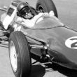
Malc2 Posted February 26, 2021 Share Posted February 26, 2021 (edited) I bought this model when it was first released in 2005 as it is pretty much my favourite F1 car of all time, short and stubby with pugnacious looks and in conjunction with the great Jackie Stewart bagged the 1973 drivers world championship which marked the end of his career. Needless to say I started the kit as soon as it arrived, but being a bit disappointed by the fidelity of the castings, it was almost as quickly put aside in lieu of a Tamiya BT46. In the meantime MFH released their 006 in 1/20 and 1/12 scale, the instructions proving very useful in discovering hidden details, and if you can afford them, MFH are far superior. But where is the fun in that??!! I better get a move on as Ebbro keep threatening to release their 1/20 005 and 006, it will be interesting to compare the two and you can be sure it will be released just before I finish this one… So it languished in its box until the Lotus 101 was almost complete, and while I was waiting for filler/glue/paint to dry I got it down from the SOD and poked the bits around, and got inspired – at least for a bit. So this is what you get in the box. The PE is great, nice wing end plates, seat belt ends, radiator screen and vented disks. The kit represents Stewarts pole position and win at Monaco in 1973. This was also the first F1 race for a certain James Hunt. Unusually for a resin kit the main castings were almost totally bubble free, but as we all know they will be lurking under the surface to be revealed just as soon as the modifying starts. The proportions look good, but the bad bits are blurred detail, very thick edges where they should be waffer thin and the interior only bears a passing resemblance to the real car – which to be fair is the same as all the interiors of the resin F1 kits I have come across. However there is one area that really lets the kit down and that’s the instructions – down right misleading and or vague in important areas. You really need good ref photos for this. However, challenge accepted and nothing a bit of sandpaper, plastic card and filler can’t fix Apparently….. Apart from the tyres, one rear had a crack and kudos to the kit supplier, a complete replacement set was despatched promptly without question and at no cost. The part I started way back in 2005 was the rear wing, which suffered from some serious mould collapse, the photo makes it look better than it is. So I set to and made a replacement from plastic card, a drawing was prepared, prob a bit OTT, but just because…… Part cut And with a bit of boiling water, a suitable diameter pen, clothes pegs and some glue, the wing was folded over and the reflex fixed in. I made the wing from 20thou plastic card which turned out to be too thin and flexible. The filler flaked off when I was sanding it, even though I scored the plastic to provide a key. For plastic card this thin what is really needed is a solid balsa core a la Harry Woodman. So as I was living abroad at the time and had limited access to raw materials, it got put back in its box. And so it sat on the shelf of doom - until now. I pulled out the original cast rear wing and made a new one from Ureol, (a grainless easy to sand composite used for pattern making) cut the support slots on the underside, added the PE end plates and flow straighteners, added a coat of primer and Bobs your neighbour – or something like that. I primed the wing first just to see how the paint took (not great – had to go round again), then added the PE and primed again. 2nd coat of Primer Howie held it while spraying Buoyed by that easy win, I perused the other kit parts, and picked out the three piece rear roll bar as the next candidate for a makeover. The manufacturer appeared to think that the ends could be butt jointed to the main piece, I didn’t think this would work very well. Original So break out some 1mm electric cable relieved of its plastic overcoat (core straightened by rolling on a flat table under a block of wood – don’t do it on your best dining table), a few pieces of plastic card suitably massaged to the required shape, tack the engine and trans together, add some 0.5mm steel pins to the gearbox casing to hold the roll bar support in place, a quick look at some ref matl and Robert is your moms brother. At the same time I drilled the rear uprights to accept more 1mm copper wire as radius arms. Tried and failed to turn one driveshaft on the lathe to restore its roundness, - the tool tip dug in and twisted the shaft off the inboard joint, so I had to make a replacement shaft and outboard joint, then drill the upright to accept it and repeat selected highlights for the other side. The top links were drilled and fit, they govern the camber angle by sliding the inboard end mountings in and out along the roll bar support. Just for fun I added some detail to the bottom of the transverse links, copying the part from a Tamiya P34 The rear uprights were milliputted (is that even a word?) about 3mm wider to match the width of the transverse link Meanwhile I spent a LOT of time refining the body. The cockpit side strakes (which were to prevent the hot air from the radiator outlets in the nose cooking the driver) were sanded to the correct triangular profile from the as cast square shape. All the body edges were thinned to about 0.5mm from the 3 to 5mm as cast. Panel lines were straightened and refined, the body sides straightened and edges sharpened up. The white metal engine intake opening was drilled out and it plus the rear fairing were superglued to the body and the whole lot given a couple of coats of primer. Two things to note here, the rear fairing is too low (oops) and the top of the seat is part of the main body casting. Despite washing in soapy water, several fisheyes appeared, the trick is to let the paint fully dry, sand, and lightly mist over again two or three times, waiting 48 hrs between coats. Cockpit interior – the 5mm thick radiator housing floors were cut off and replaced with 1mm card, the supports for the instrument panel were added and some large gaps in the floor to body were filled with strips of card and a piece of card added to square up the rear face of the tub and two other pieces to fill the empty voids on each side that would otherwise be visible when viewed directly from the rear. It occurred to me at this point that the finished body/seat assembly would result in an unsightly join across the shoulder area of the seat, so I took a couple of brave pills, broke out the thinnest PE razor saw I possess and separated the top of the seat from the body. Initial lengthways cuts along coaming sides. The solid block of resin above the engine intakes was savaged from underneath with a dremel until light could be seen through the casting walls and then the vertical cuts were made below the intake (through the now 1mm ish thick walls), releasing the top of the seat. Which was immediately superglued to the top of the seat, later some filler was added to cover the join. The underside of the body below the intake was flat across the whole width of the rear deck – You can see below how much I ground out and how thick the outer radiator surround was before I sanded the tapers in, I did not go any thinner otherwise the radiator PE mesh would be too narrow, I am hoping the final SG black finish and the mesh screen will hide the over scale thickness! While the mad scientist was loose with the dremel, he ground out the clearance for the drivers hand/gear lever. Here you can also see the card additions to positively locate the rear floor vertically and the thinning of the cockpit sides. At this point I did consider removing the cockpit surround from the tub to be able to improve the cockpit interior/tub, but I want to finish it in this century - SABLE and all that. Moar soon mes amis. Malc. Edited February 26, 2021 by Malc2 spelloing 13 Link to comment Share on other sites More sharing options...
Stickframe Posted February 26, 2021 Share Posted February 26, 2021 Hi Malc, This build will be great to watch - looking forward to seeing how it all comes together. Nice to see you cut the air intake out. It seems many of the resin kits send out blocks of materials for key body parts, but skip out even general representation of the underside. I usually consider carving/cutting the bulk material out too, and typically remove at least some of it. I've got a kit lined up for the next project and will need to consider how much to cut! So interesting to see how you're doing this. On another post you asked me about some photo etch I used. It was remnant from an Eduard 1/35 set for the exterior of an MATV (an armored vehicle). I enjoyed building the kit and variants so had extra material, which of course I keep for just such a situation! Cheers Nick 2 Link to comment Share on other sites More sharing options...
Malc2 Posted February 27, 2021 Author Share Posted February 27, 2021 Cheers Nick, Thanks for that, I thought they might bespoke PE suspension pick up points, I have seen a set of these for sale somewhere and can't remember where! M. Link to comment Share on other sites More sharing options...
silver911 Posted February 27, 2021 Share Posted February 27, 2021 Another classic build in the making Malc...and a favourite of mine too Ron Link to comment Share on other sites More sharing options...
Bengalensis Posted February 27, 2021 Share Posted February 27, 2021 Very nice work! Link to comment Share on other sites More sharing options...
Stu_davros Posted February 27, 2021 Share Posted February 27, 2021 Awesome work, your rear wing looks 100% better than the kit parts. I have a number of ACE kits and they need a lot of work, particularly the white metal parts so I can see the work you have put in just to make them useable is amazing. I look forward to your progress, it may inspire me to break out my Brabham BT45C. Cheers, Stuart Link to comment Share on other sites More sharing options...
Malc2 Posted February 28, 2021 Author Share Posted February 28, 2021 (edited) On 2/27/2021 at 8:11 AM, silver911 said: Another classic build in the making Malc...and a favourite of mine too Ron Thanks Ron On 2/27/2021 at 8:58 AM, Bengalensis said: Very nice work! Cheers Jörgen On 2/27/2021 at 12:33 PM, Stu_davros said: Awesome work, your rear wing looks 100% better than the kit parts. I have a number of ACE kits and they need a lot of work, particularly the white metal parts so I can see the work you have put in just to make them useable is amazing. I look forward to your progress, it may inspire me to break out my Brabham BT45C. Cheers, Stuart A BT45C would be great to see, so when do you start!?😀 Malc. Edited February 28, 2021 by Malc2 spellingang Link to comment Share on other sites More sharing options...
Vesa Jussila Posted February 28, 2021 Share Posted February 28, 2021 Good work so far. Interesting subject. One more to follow. Link to comment Share on other sites More sharing options...
Malc2 Posted February 28, 2021 Author Share Posted February 28, 2021 So Guten Tag meine Leiblings, lets get caught up some more. The sides of the body by the radiator were further refined to lower the join between body and rear floor Floor in place, it looks like a gap at the front, but its filled with superglue. To provide a positive and repeatable location for the engine, a pin was added to the body, matching an existing hole in the front of the engine. Much marking out and procrastinating over the height of the engine ensued, as it became clear that there is not enough room for the engine under the body if the sump is flush with the underside of the tub. I removed as much of the body as I dared, but still had to sand a bit off the valve covers to get it all to fit. Once it is all together you can’t see the top of the engine, so I’m not going to worry about it too much - curbside! The rear bulkhead evolved again to make it flat across the entire width providing more robust mounting points for the 4 trailing arms. Cut outs for the cam cover mounts were made preventing the engine rotating round the locating pin. Apart Together The gearbox also had the same treatment, it was filled with Milliput and a pin pushed in while it was soft. When hard the procedure repeated on the engine side, the pin being removed while the filler was soft. Reassembly when it was all hard showed we were in the ball park. A shim was added to the trans flange to correct an angular misalignment in the casting. The pin is still removable from the trans so it can be easily sanded across the whole face to get the correct alignment. Now the whole lot could be positively dry fit without rolling all over the bench every time I breathed out. The trailing arms were bent to shape and located in the body, this is not strictly correct as the top arms should locate to a bracket on the cam cover and the lower ones on the main roll hoop, but again as it can hardly be seen when assembled, life span and all that. The aim of all this is to get the rear wing positioned in the right place relative to the body, and the struttery made to join the two. So bring on another jig. Some graph paper was pritt stuck (other glues available) to the lid of the now redundant Lotus 101 box, and after several rounds of measuring and cutting, various bits of balsa were stuck down to locate the body, engine and trans at the correct ride height and square to the centre line. The one bit of truly useful info on the kit destructions are the dimensions to the underside of the body to set the front and rear body height. No body Some body Starting to look like an 006 – just look at those mahoosive rear tyres. The point of adding the wheel/tyre assembly was to establish the height of the hub carriers which is fixed by the wheel centre height, so then the lengths of the shocks and roll bar links could be accurately worked out. At this point I became aware that some clown had stuck the rear triangular fairing on far too low, (remember I mentioned this at the beginning?) so muttering curses at past me for not paying attention, I carefully cut it off and reglued it to follow the top line of the intake box. This then meant that the lower edge of the triangular fairing was too high, so several layers of Milliput were added and faired in. It should also have slightly concave sides and a thinner spine, so I ground the back of an old model knife blade to a slight curve and scraped the sides until I got a much more svelte looking rear fairing. Removing just a little to go from convex to concave makes a big change to the appearance of the fairing Surface looks quite scored after scraping away the excess But providing it has been done evenly, a few swipes with sandpaper gives a smooth surface, the colour change in the filler is old Milliput (bought circa 1995) Vs new (2019) Milliput, (my second ever box of Millput, I’m not their best customer….) the new is much softer out of the packet so easier to mix, it seems about the same hardness when set. After much trial and error and checking period photos, the rear wing position was established and fixed with suitably positioned pillars of balsa. Much care was taken to ensure wing to body squareness and parallelosity, after much studying of period photos, the bottom edge of the rear wing end plates appears to be on about the same plane and at the same angle as the top surface of the body. Once this was done the rear wing support could be scratched - the white metal kit parts were not worth bothering with. While I had the filler out for the rear fairing I added some to the tips of the front wheel fairings to extend them backwards and give a slight radius following the curve of the front tyre. Finished wing support On its own with errant pin for location to the gearbox. The barely visible litho plate brackets at the bottom right are for the wing end plate stay. Coupla gratuitous shots of the body as it currently is Full side Front fairing tip additions And the underside of the body showing the additions and mods to date (Nearly) Original Now Thanks for looking, Malc. 9 Link to comment Share on other sites More sharing options...
silver911 Posted February 28, 2021 Share Posted February 28, 2021 That's some serious work in correcting the shortfalls in this beast Malc...and stunning attention to detail/accuracy...superb results Much respect. Ron Link to comment Share on other sites More sharing options...
Bengalensis Posted February 28, 2021 Share Posted February 28, 2021 You're making great progress, very well done! Link to comment Share on other sites More sharing options...
Sabrejet Posted February 28, 2021 Share Posted February 28, 2021 F1 isn't my bag, but there's no denying great modelling: will be watching with interest! Link to comment Share on other sites More sharing options...
Malc2 Posted March 5, 2021 Author Share Posted March 5, 2021 Thanks chaps, your too kind. M. Link to comment Share on other sites More sharing options...
Malc2 Posted March 5, 2021 Author Share Posted March 5, 2021 Greetings all, next update. Now that the whole of the rear drive train was located together positively in the jig, and the height of the rear upright centres established, I could make the roll bar link, the top connection is made from more 5thou litho plate. Having done that, the dampers were next, and came up a bit short, the top should locate on the pin projecting from the roll bar mount Same, from a different angle Using the kit top and bottom, new middles were made from brass and plastic tube. Complete with new 0.6mm dia wire copper springs, the collar at the top was a late addition to locate the top of the spring concentrically with the top mount Continuing towards the back, the exhaust mount was PE, it lacked a bit of 3Dness and the hole for the exhaust does not reflect the original bracket, so using more 1mm copper wire and a strip of PE brass cut from the edge of the fret a new one was fabbed up. PE part as template and a forest of pins holding the parts ready for soldering. After filing a location groove in the bottom of the gearbox and receiving holes in the upper casing, Voi et La With end casing temporarily in place And with end end casing in place - scratched as I lost the kit part – bloomin' carpet monster again, it got it somewhere between 2005 and now. image upload First trial with exhaust bits, after some tweaking to fit and a lot of sanding to remove mould lines and improve the shape, looks promising as a start. So now the rear is pretty much complete, Well – apart from some additional struttery that connects the roll bar mounts to engine block and head, which I will leave until the main parts are painted and glued in place, otherwise its all just too fiddly chasing parts round the bench as they roll off to be consumed by the carpet monster or sping off in to oblivion. Thanks for looking, comments welcome! Malc. 7 Link to comment Share on other sites More sharing options...
ddw867 Posted March 5, 2021 Share Posted March 5, 2021 On 2/28/2021 at 3:37 AM, Malc2 said: parallelosity Learned something new today, Thanks! 1 Link to comment Share on other sites More sharing options...
Bengalensis Posted March 5, 2021 Share Posted March 5, 2021 More beautiful work 👍 Link to comment Share on other sites More sharing options...
Malc2 Posted March 6, 2021 Author Share Posted March 6, 2021 On 3/5/2021 at 11:51 AM, ddw867 said: Learned something new today, Thanks! English is such a great language to play around with isn't it! You can make up a word and people still know what you mean. On 3/5/2021 at 12:06 PM, Bengalensis said: More beautiful work 👍 Thanks! M. 1 Link to comment Share on other sites More sharing options...
Malc2 Posted March 6, 2021 Author Share Posted March 6, 2021 So where was I, oh yes the front……. From the top:- Brake calliper and wheel nut/spindle Embryo new spring (because kit springs are like biro springs) and kit damper In/on the lower wishbone - home made PE bracket for lower shocker mount, pin for roll bar link New driveshafts, because - white metal, poor fit and round bits not round Original driveshaft Holes drilled in body to take wishbones and driveshaft. The steering rack and roll bar holes still to be made. The ever evolving jig now with shims to hold the front lower wishbone at ride height. It aint pretty but it does the job With that little lot in place and the car at the correct ride height, oh surprise quelle surprise the damper don’t fit, this time its too long. Wheel centre close enough – you can just about see here that the hole in the middle of the wheel is, well, not in the middle of the wheel, I see this as an advantage as I can rotate the wheel in the event of a three legged stool event occurring after final assembly. As long as we can keep that between all of us kids here, no one will ever spot it. Rolled aside Next is the roll bar, it has to squeeze below the upper wishbone and above the driveshaft, so about 0.5mm each side clearance – no pressure then. This is what the kit provides. Surprisingly the drop links are exactly the right length but the upper eye is too small to go over the roll bar, so replacements will be scratched. In position - albeit should be under the body, so it’s a bit short. No matter - plenty spare to be had from a MK1 rear rollbar of which several iterations were made, this one was not wide enough. The Ace kit instructions were suitably vague about the position of the calliper round the brake disc, according to the Hiro instructions the brake callipers are on the rear of the disks. First up the calliper did not fit fully over the disk A bit of filing the internal surfaces sorted that Next the calliper did not fit the intended position either way round, this is how I thought it was going to go Flipped over it looks more promising, but still fouls the body and pushes on the disc You can’t really see it here, but the corner radii need removing to allow the calliper to fit Removed, coincidentally now mirroring the actual car….. That along with removing the unwanted spigot and hey presto, much better The front dampers and springs were shortened to fit All parts test fit in place New roll bar links were made, the eyes were made by squishing the end of the rod with a pair of pliers and adding a couple of small pieces of card each side, sanding it round, then drilling a hole through all 3 pieces. Finished roll bar link in place. The upper rear wishbone mount was shaped to be more accurate, I also realised I had glued the lower damper mount 90deg out, luckily having used superglue it could be just pinged off (technical term) and re glued. Which completes the front suspension, just some final polishing to remove file marks and the parts will be ready for paint. Lots of subtle bending of the upper and lower W/bones had to be done to get it all to fit properly. The brake duct exits were made from litho plate to replace the REALLY thick kit parts, the tabs fit in the duct hole and give something to glue to the body rather than just the edge, fortuitously the radius on the edge of my model knife handle was perfect to form the ducts around. Test fit - looks good compared to kit part. Second part made and dry fit Thanks for looking, Comments welcome! Malc. 11 Link to comment Share on other sites More sharing options...
silver911 Posted March 7, 2021 Share Posted March 7, 2021 Yet more stunning work Malc...absolutely superb. Respect Ron Link to comment Share on other sites More sharing options...
Vesa Jussila Posted March 7, 2021 Share Posted March 7, 2021 Really nice work with suspension. Link to comment Share on other sites More sharing options...
Malc2 Posted March 8, 2021 Author Share Posted March 8, 2021 Thanks gents, at least someone is reading my drivel! Malc. Link to comment Share on other sites More sharing options...
Stickframe Posted March 8, 2021 Share Posted March 8, 2021 Wow Malc, You haven't been wasting any time with this build! Lots of great work going on here - I'll have to go through it again. The litho plate is a really good idea. Someone mentioned it to me before, but I have not, or ever seen it used - really looks like something to keep handy! That front end looks like it was quite a headache, but also looks like you're getting it squared up. I really like the bracket you built for the exhaust tips, a fine piece of work. In my recent round of DFV projects, it seems that inevitably, one of the banks of headers goes together effortlessly, and the other a complete nightmare - and I haven't a clue why! then the kit brackets have been PE, not the metal you've used, only adding to the headache! Looking forward to your next update! Cheers Nick Link to comment Share on other sites More sharing options...
klubman01 Posted March 10, 2021 Share Posted March 10, 2021 Some great craftsmanship going on with this build. You have come up with some ingenious and clever solutions to the problems you've encountered. Great stuff so far. Trevor Link to comment Share on other sites More sharing options...
Malc2 Posted March 14, 2021 Author Share Posted March 14, 2021 (edited) Thanks both. Welcome to this weeks update! When grinding out the inside of the gear lever bulge, I also thinned the inside of the cockpit sides some more, this left a large gap each side of the seat. On the real car this gap is filled with the inner corners of the body tub. I was not sure how to best resolve the shape of the tub which should fill this gap, in the end the solution was simply to build up Milliput on the seat sides, the instrument panel was moved a bit nearer the driver at the same time. The drivers knees were protected by padding on the underside of the dash and cockpit sides, nothing in the kit for this, so pads made from Milliput. The gear change linkage was not long enough so a new one was made and the guard made from a scrap piece of PE ‘sprue’. Old Vs new in progress The lever has to be fitted to the rod after the guard In place in the car, fitting the gear mech showed that the new sides of filler needed more sanding to allow for the rod to pass through a hole at the side of the seat. I made the missing (oxygen bottle/fire extinguisher?) cover that fits below the seat. A piece of tube rounded off with Milliput, glued to a square of 10thou card which was sanded to an oval to form the flange. I was never really happy with the floor where it joined the bottom of the sidepod wall, as the resulting non scale join would be highly visible on the outside of the finished model. I finally realised I need a rebate to disguise the join. Strip of plastic added to the body and the floor narrowed to suit. Both sides done Floor fully home Apart from a couple of smears of filler, I think the body is ready for another round of primer. Well the smear of filler turned out to be a great big lump after I spotted the shape of the rear of the nose in some reference photos. With the bluff nose there were two styles, one that was completely open across the back and one which was closed, the closed one included the curved piece made from filler you see below, I could not do the open one as the edges made of filler would just crumble away, I need to try automotive filler, as suggested by @Bengalensis! Underneath, just a bit of final tidying and ready for paint, oh no, wait…… the rear deck But before that, I addressed the issue of the front tyres which are a bit shrunken in the middle, I cut a strip of 30thou card and bent it in to a circle with the help of some hot water And fit it inside the tyre making sure the ends butted together Push the tyre back on the rim and almost gone, just need to sand away the mould line. Quick spin on the lathe and the mould lines were removed with some coarse grade sandpaper Pre scrubbed and ready for use Next week, I finally get round to the rear deck and those there right horrible louvres. Thanks for following. Malc. Edited March 14, 2021 by Malc2 additional comments 7 Link to comment Share on other sites More sharing options...
Harry Callahan Posted March 14, 2021 Share Posted March 14, 2021 Even F1 kits are not my bag, i follow your thread with huge interest. Yes english language is easy to learn in opposite to german. Thats why i must correct you, it calls Guten Tag meine Lieblinge not Leiblings🤣😋🤫 Link to comment Share on other sites More sharing options...

Recommended Posts
Create an account or sign in to comment
You need to be a member in order to leave a comment
Create an account
Sign up for a new account in our community. It's easy!
Register a new accountSign in
Already have an account? Sign in here.
Sign In Now