DocJonno Posted February 12, 2021 Share Posted February 12, 2021 Have given up on version 4 as wired internals incorrectly so started v5. I'm using airfix spitfire 1/72 mk1a as the base. First job is the wings and cutting wiring channels for the lights. Using 0.1mm flat LEDs. The ultra thin wires only need a small groove. 1 Link to comment Share on other sites More sharing options...
DocJonno Posted February 12, 2021 Author Share Posted February 12, 2021 Started assembling without showing so here's it reopened. The lights (after dipping in tamiya clear colours) are routed through channel and superglued. I try and glue as perpendicular as possible. I then use so putty to fill the gap and sand smooth. I try and make the lights look like they come out like on a spitfire wing albeit they are proportionally to big. Link to comment Share on other sites More sharing options...
Sparkie Posted February 12, 2021 Share Posted February 12, 2021 11 minutes ago, DocJonno said: Started assembling without showing so here's it reopened. The lights (after dipping in tamiya clear colours) are routed through channel and superglued. I try and glue as perpendicular as possible. I then use so putty to fill the gap and sand smooth. I try and make the lights look like they come out like on a spitfire wing albeit they are proportionally to big. Have you twisted bare copper wires there or are they insulated? Link to comment Share on other sites More sharing options...
DocJonno Posted February 12, 2021 Author Share Posted February 12, 2021 Hi. I use ready soldered parts - from amazon 'evemodel 0603w'. The wires are lacquered and require either scraping or burning to remove. Absolutely fiddly! 1 Link to comment Share on other sites More sharing options...
DocJonno Posted February 12, 2021 Author Share Posted February 12, 2021 And the USB port. Using a mini USB b female and soldered some wiring. This is where I messed up last model as put the positive negative the wrong way round. These wires go to the battery an a switch. The USB female sits in the radiator at an angle so that a charger can plug in. You have to cut a hole in the wing above radiator to fit this in and have wires through. I used araldite to hold USB in place and ensure wires are firm as well and not slip around. You can see the angle and position of USB in version 4 1 Link to comment Share on other sites More sharing options...
DocJonno Posted February 12, 2021 Author Share Posted February 12, 2021 And remove this nubbin for another led 1 Link to comment Share on other sites More sharing options...
DocJonno Posted February 12, 2021 Author Share Posted February 12, 2021 (edited) And LED in place with a bit of plastic to help secure https://www.flickr.com/photos/192157755@N08/50936273507/in/dateposted-public/ Edited February 12, 2021 by DocJonno 1 Link to comment Share on other sites More sharing options...
DocJonno Posted February 12, 2021 Author Share Posted February 12, 2021 I use a small switch to fit into the precut hole. I've had to cut the bar and make the hole wider by about 1mm to accommodate the switch And then use araldite to hold it in place being careful not to put any on the moving part of switch. I've also wired up a 70mah LiPo battery and the charging cable. The charger is on one circuit and the lights are on another circuit. The switch turns lights off and opens the charging circuit (and thus isolates the led and subsequent motor for the 5v input). The resistor tones down the lights a little as they are very bright! 1 Link to comment Share on other sites More sharing options...
DocJonno Posted February 13, 2021 Author Share Posted February 13, 2021 Some more progress. I don’t do fancy painting for the internal pilot bits as can hardly see when canopy closed. Part b26 is not used as need clearance at that area for wires. A10 and a9 are also cut short. The 4x8mm motor has a very short shaft so have to cut into plastic a bit to move 1mm forward. The propeller part at has to be cut and a hole made to accommodate motor. I use a hot needle to make this hole. I tried prepainting the propeller but it hasn't worked so I'll have to fit properly later. 2 Link to comment Share on other sites More sharing options...
Rumblestripe Posted February 13, 2021 Share Posted February 13, 2021 Fascinating idea! I'd never thought of putting a rechargeable battery inside a model (well it's new to me) I expect you will be doing the flashing lights in the gun ports? (Joking!) 🤡 Link to comment Share on other sites More sharing options...
DocJonno Posted February 13, 2021 Author Share Posted February 13, 2021 Gun port flashing leds sounds like an idea! I'll need to find a suitable flashing unit/transistor but I think an led would fit in. Would be good with the sound effects too but a sound module is way too big to fit in! 1 Link to comment Share on other sites More sharing options...
DocJonno Posted February 13, 2021 Author Share Posted February 13, 2021 Put together and put undercoat on. I did wire up a tail light which was really fiddly and didn't take pics. Same process as the wing tip lights. I did add a 3mm flashing led in series to allow this tail light to blink and that 3mm led is hidden inside. Ready for painting now and putting propeller on 1 Link to comment Share on other sites More sharing options...
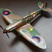
DocJonno Posted February 14, 2021 Author Share Posted February 14, 2021 So finally painted with some different BoB decals. Might add some weathering at some stage. .... Next project is an electrified Boulton Paul Defiant! 5 Link to comment Share on other sites More sharing options...
SaminCam Posted February 14, 2021 Share Posted February 14, 2021 Awesome, love this! 1 Link to comment Share on other sites More sharing options...
Sparkie Posted February 15, 2021 Share Posted February 15, 2021 Looks great, how is the switch operated? does the whole intake move? 1 Link to comment Share on other sites More sharing options...
DocJonno Posted February 15, 2021 Author Share Posted February 15, 2021 46 minutes ago, Sparkie said: Looks great, how is the switch operated? does the whole intake move? Thanks. The switch is glued to the intake so you can't see the black part of the switch (and the switch is now the whole intake which slides back and forth). You have to cut a very small square approx 1mm deep into the intake part to accommodate the black part of switch and a tiny blob of araldite so that only top of switch glues and doesn't overflow. Very easy to glue intake to underside of plane and cause switch to stick. 1 Link to comment Share on other sites More sharing options...

Recommended Posts
Create an account or sign in to comment
You need to be a member in order to leave a comment
Create an account
Sign up for a new account in our community. It's easy!
Register a new accountSign in
Already have an account? Sign in here.
Sign In Now