perdu Posted February 7, 2021 Share Posted February 7, 2021 Jerzy this is how I do vacforming of clear parts. I built a box with a hole in the end to fit the vacuum cleaner nozzle and drilled a lot of holes in the top to make the airbox work. (I use wide tape over parts I do not expect to use to make as much use of the suction as possible) You can see that I added foam draught excluder strips around the box's vacuum surface, these seal the edges. I make the buck longer than it needs to be and when drawing deep such as the bubble nose for my recent Belvedere I add extra depth below the surface, these are a pair of one pound coins, euros work as well by the way, as they do for supermarket trolley hire. If I was making the buck for your Lerwick I would mould it from Milliput, the very best mould buck material I have ever found. I have a two-piece moulding frame with a hole big enough to fit over the mould buck in position and place the moulding material between the two pieces then close the pair by pushing drawing pins down to hold both panels together. A crude hinge made from duct tape makes the pair of plates stay together when opening it up after moulding, this way the holes for the drawing pins stay aligned for use. The above is very wasteful of material so in use I prefer the smaller hole version shown next. The materials I prefer are either acetate sheet or PETg, both work. I buy it from eBay in packs of five and it's not too expensive. I hold the panel of clear stuff up off the one end of the vacformer, start the vacuum and heat the panel with a hot air gun. PETg forms bubbles inside unless you warm it up a couple of times before you stress it in the vacuum for real. Let the clear sheet begin to ripple and wobble a few times by getting close then pulling back from the sheet, then hold the hot gun a little closer and guide the sheet down onto the box. When you do it right the vacuum will pull the material into the little holes, stop the heat and the vacuum source and when it cools lift it off the box and cut out the canopy. I usually find my first try is my best try, I do not know why that is Some canopies to be trimmed back and the best one to be selected for use. I hope this helps you a bit, apart from the device the most important thing is to make the buck properly, Milliput is your friend for that. 4 1 Link to comment Share on other sites More sharing options...
JWM Posted February 8, 2021 Author Share Posted February 8, 2021 Perdu, many thank for tutorial. I will do photos of my setup but I think I see already my mistakes.... Regards J-W 1 Link to comment Share on other sites More sharing options...
JWM Posted February 8, 2021 Author Share Posted February 8, 2021 (edited) Hi So this is a general view of mine vacu set: So there is a set of three frames glued together on a fourth board, from bottom you have pipe for pump, the paper works as a seal the plastic is put between paper and external frame and all is mounted using four screws. The inside looks like this: So there is a steel net, below the wood is cut forming air drain system. First of all I think it is too deep, it is about 3.5 cm deep whereas I see that experienced people ( @perdu, @AdrianMF ) made the base rather flat. My Milliput male form looks like that: Some cracks appeared it course of many attempts so far, so I filled them with CA gel glue and sanded... I did already two copies of Bombay props , but I am not happy with their shapes, much better look propellers from Valom Harrow, so I am copying now those props and even intend to replace the original Bombay one in mine kit (darker is original) And wing after first sanding, already with new portion this time of Tamiya putty That is all so far... Regards J-W Edited February 8, 2021 by JWM 12 Link to comment Share on other sites More sharing options...
AdrianMF Posted February 9, 2021 Share Posted February 9, 2021 The wing looks incredible! I’m loving the way you are adapting your spare parts. I’m a great fan of two-part auto putty for big structural work because it sets quickly with no shrinkage, and it sands well with plastic. I suspect it’s a lot cheaper than modelling putty too! Regards, Adrian 3 Link to comment Share on other sites More sharing options...
Max Headroom Posted February 9, 2021 Share Posted February 9, 2021 This is turning into an epic👍🏻 Looking forward to your next update. Trevor 1 Link to comment Share on other sites More sharing options...
RidgeRunner Posted February 9, 2021 Share Posted February 9, 2021 Great stuff, Jerzy! I've never vac formed anything so it is really interesting Martin 1 Link to comment Share on other sites More sharing options...
JWM Posted February 9, 2021 Author Share Posted February 9, 2021 (edited) 14 hours ago, AdrianMF said: The wing looks incredible! I’m loving the way you are adapting your spare parts. I’m a great fan of two-part auto putty for big structural work because it sets quickly with no shrinkage, and it sands well with plastic. I suspect it’s a lot cheaper than modelling putty too! Regards, Adrian I like also to use car body repair putty (resin one) but it smells terribly, so when we have now -10 C in nights outdoor I am trying to avoid extensive opening of windows and otherwise my wife will seriously complain an odor... Last time I used it for nose of MB 220, it was in warmer weather... Here I am a bit afraid about further shrinking of normal (fixed by evaporation) putty So I was trying to use Milliput for most of structural elements.. Regards J-W Edited February 9, 2021 by JWM 1 Link to comment Share on other sites More sharing options...
JWM Posted February 9, 2021 Author Share Posted February 9, 2021 On 2/7/2021 at 5:55 PM, bentwaters81tfw said: Have the bits arrived yet? Many thanks! today they arrived! I want to send you something in return - I was trying to figure out your preferences., what could be interesting for you to get.. regards J-W Link to comment Share on other sites More sharing options...
Marklo Posted February 9, 2021 Share Posted February 9, 2021 THis is my mkl vac form setup a metal box bought off eBay holes drilled in the lid and a vacuum connector duct taped to it, and a modified picture frame. But it works pretty well ( I’m working on a better setup but I haven’t ironed out the kinks yet) Some of the results. 6 Link to comment Share on other sites More sharing options...
JWM Posted February 18, 2021 Author Share Posted February 18, 2021 Hi, After some pause I am back... Many thanks for tutorials about vacuforming, I was talking also with my colleague who is owner of small modelling company Taurus (mostly resin aftermarket details for 1/35 AV and dioramas, but also highly detailed engines of WW1 airplanes). BTW - he has got some prize in Telford a couple of years ago for his products. Anyway he is experienced also in vacuforming - beside tutorial he gave me some proper foils. We will see, .. I do not want to spoil it so I have to prepare better myself for this work. Meanwhile I started to cut out smaller side floats from Sunderland ones which I've got recently from @bentwaters81tfw (again many thanks!) After few cuts and removing excess material they have now proper size, the surface needs still more work: I was continuing work on wings. I decided that I have to start construct engine nacelles. Starting from top one - I cut out the Wellington (Frog/Novo) nacelles made it more narrow by by cutting out some narrow wedge (~2 mm at front) Then I glued them in position I put some filler in join of nacelles with wing, secured by tape for future sanding. I am planning to trim a bit them from length at front, since the part just behind the cowling I want to from a pieces of nacelles I had from Airfix Halifax, after my conversion of radial Halifax into Merlin on based of Airfix kit (some 15 years ago - here it was on RFI 😞 To be continued Regards Jerzy-Wojtek 14 Link to comment Share on other sites More sharing options...
Cees Broere Posted February 19, 2021 Share Posted February 19, 2021 Fantastic! 1 Link to comment Share on other sites More sharing options...
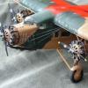
JWM Posted February 20, 2021 Author Share Posted February 20, 2021 On 2/19/2021 at 9:17 AM, Cees Broere said: Fantastic! Thank you!!! I trimmed the nacelles and glued on front of them pieces from Halifax nacelles (up side down) . I used Tamiya resin (epoxy) filler to modify shape of nacelles on top. You may see that I started scribing surface. On bottom I made some plastic construction and put again Tamiya resin filler around to construct the bottoms of nacelles which housing the bomb bays. I cut out the landing lamps place on leading edge. Some parts for detailing: MPM Cowlings and engines from Wellington Mk X and floats after sanding The cowlings are a bit (perhaps 1.5 mm) too long, so I will have to cut them a bit. A temporary set of cowlings on position: The aperture is a bit too small, but I have to check it on photos To be continued Regards J-W 11 Link to comment Share on other sites More sharing options...
JWM Posted February 23, 2021 Author Share Posted February 23, 2021 (edited) Some more progress: next round of sanding and putty work. Besides on bottom side I drilled openings for float struts, added oil coolers made a landing lamps. The landing lamp cover I cut from a clear packing stuff. Oil coolers are from Airfix Halifax. I shorted cowlings by about 1 mm (from middle part by surgery) and increased diameter of front opening by another 1 mm. The mid cowling scarf is subject of filler/sanding work... The air intakes will be also from MPM Wellington (must be shorted by some 5 mm). I painted engines and also drilled them through since I like to have props rotating: To be continued Regards J-W Edited February 24, 2021 by JWM 10 Link to comment Share on other sites More sharing options...
TheBaron Posted February 24, 2021 Share Posted February 24, 2021 Surgery + engineering = surgineering. Ambitious and precise work Jerzy! 👏 1 Link to comment Share on other sites More sharing options...
JWM Posted February 24, 2021 Author Share Posted February 24, 2021 3 hours ago, TheBaron said: Surgery + engineering = surgineering. Ambitious and precise work Jerzy! 👏 Many thanks! but - come on, I've seen some yours builds. that was real surgineering, I am just trying Regards J-W 1 Link to comment Share on other sites More sharing options...
JWM Posted February 24, 2021 Author Share Posted February 24, 2021 Hi The further work on engines, the air inlets on top of cowlings (well, behind it rather). They are made from a MPM Wellington Mk X (spare parts of Wellington stay with me since I did Mk VI from one Mk X kit). Of course they need some use of putty and sanding: The floats (still requires small sanding/putting round): The Valom Harrow prop immersed in silicone: To be continued Regards J-W 5 Link to comment Share on other sites More sharing options...
JWM Posted February 26, 2021 Author Share Posted February 26, 2021 Hi, I noticed something about the canopy. On this photo the part of canopy above the second pilot looks opaque. Or it is just illusion? Second question is about the keystone shape (almost triangle) dark object below the porthole behind the canopy. What it is ? (it is visible on both sides). This photo suggests that it is a window...BTW - here no opaque part of canopy Here again the canopy is all glassy... 1 Link to comment Share on other sites More sharing options...
Pete in Lincs Posted February 26, 2021 Share Posted February 26, 2021 Perhaps on some aircraft the canopy part could have been painted over. Not unknown on other WW2 aircraft. The odd shape behind the canopy looks like an air intake to me. 1 1 Link to comment Share on other sites More sharing options...
JWM Posted February 26, 2021 Author Share Posted February 26, 2021 Thanks! I continued to scribe panel lines Tailplane And upper side of wing. I painted with EDSG to see how the surface looks like Fuselage (still part behind canopy is under construction) got openings for portholes Temporary set of wings and fuselage together: To be continued Regards Jerzy-Wojtek 10 Link to comment Share on other sites More sharing options...
JWM Posted February 27, 2021 Author Share Posted February 27, 2021 I glued tailplane. It was not that easy. I had to cut some 1.5 mm from each one on fuselage sides. otherwise the span was too large. I had to drill holes and put inside a kind of spar, then glued both halves . Some filler was needed; I was detailing the cockpit (only seat belts have to add) Below ( on nose) you may also notice that I was riveting using Trumpetrer's magic wheel for riviting. Navigator's desk has a lamp!: BTW - what colour should be oxygen bottle. I made light blue, but I am not sure.. to be continued Regards J-W 9 Link to comment Share on other sites More sharing options...
TheBaron Posted February 28, 2021 Share Posted February 28, 2021 Great progress on the gross structures Jerzy! 1 Link to comment Share on other sites More sharing options...
JWM Posted February 28, 2021 Author Share Posted February 28, 2021 13 hours ago, TheBaron said: Great progress on the gross structures Jerzy! Thanks! Going further this way I glued wing and fuselage together The joinery clamp you may see is just to prevent model to flip aside, what will split fuselege and wing. I painted also fuselage and bottoms sides of wings and hull do reveal any frauds of surface before final painting work. I think that proper color for bottoms is alu not sky yet, for summer 1940 (with large fin flash era) The important next places of work to do are the gaps between wing and fuselage (seen in side photo below as place where light goes through) And the parts of fuselage in overt the top of wing near leading edge (small one) and larger at trailing edge. To be continied Regards J-W 8 Link to comment Share on other sites More sharing options...
AdrianMF Posted March 1, 2021 Share Posted March 1, 2021 It’s looking very Lerwick-like. Nice progess. Regards, Adrian 1 Link to comment Share on other sites More sharing options...
JWM Posted March 1, 2021 Author Share Posted March 1, 2021 I started to do this fuselage/wing intersection Floats on position To be continued Regards J-W 4 Link to comment Share on other sites More sharing options...
JWM Posted March 3, 2021 Author Share Posted March 3, 2021 Does anybody know, how exactly the beaching gear looked in case of Lerwick? Any possibly drawings exists? Here are some photos, but the drawings would be very helpful... http://www.rafcommands.com/database/images/aircraft/L/L7248.jpg Regards J-W 2 Link to comment Share on other sites More sharing options...

Recommended Posts
Create an account or sign in to comment
You need to be a member in order to leave a comment
Create an account
Sign up for a new account in our community. It's easy!
Register a new accountSign in
Already have an account? Sign in here.
Sign In Now