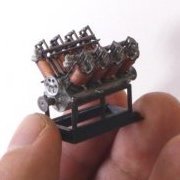
eweidenh Posted June 2, 2020 Share Posted June 2, 2020 (edited) Hi All, This is s 3d-printed model of the historic "Curtiss Number 3" engine that powered the AEA Silver Dart, as well as several other experimental craft. It wasn't a reliable engine, but it was an important step towards the development of reliable V-type aircraft engines in the US. The surviving engine is an important artifact in Canadian aeronautical history because it powered the first flights in Canada on Feb 23rd and 24th, 1909. The surviving engine is heavily deteriorated, and there is little archival evidence for certain missing parts, so this is a recreation. The model is based on a scan of the original artifact that was made at Canadian Aviation and Space Museum (CASM) on October 22nd of 2019 by members of the Ingenium conservation team. That scan provided dimensional information for a CAD model that I designed in Fusion 360. The model is published on Thingiverse, along historical details, instructions, and information on the project. The model can be printed using any reasonably recent and decently calibrated FDM printer. The version show above has both FDM and SLA-printed parts, as well as some scratch building for the pushrods and ignition cables. Thanks to everyone who provided information on the previous post. My image links disappeared, so I thought that I would repost the completed model with image links from a (hopefully) more reliable source. Below is information on the engine that I have compiled for future reference, and in case anyone would like to contribute further. Edited July 5, 2020 by eweidenh 1 Link to comment Share on other sites More sharing options...
eweidenh Posted June 2, 2020 Author Share Posted June 2, 2020 (edited) Here is an overview of what I know about the engine. The citation "BAEA" is for the Bulletin of the Aerial Experiment Association. This has been digitized by the Smithsonian, but is only available through a library subscription. I have cropped, credited, and linked the images posted below. Hopefully this falls within fair use. Fuel system: The fuel is supplied by a partitioned tank, suspended overhead, that also supplies the oil. The tank held ten gallons of fuel and two gallons of oil. The original tank and radiator are on display at the Alexander Graham Bell National Historic Site in Baddeck, N.S. When the engine was first produced it had one aluminum carburettor on each cylinder. This was later changed to a conventional manifold with one carburettor per bank. These two images show several of the changes described below. They are cropped from: Smithsonian NASM-CW5G-0908, taken on 4 Nov 1908 and Ingenium CAVM-15495, taken on 2 Mar 1909. Cylinder and valves: The cylinders are of cast iron. The piston stroke is 3 3/4 x 4. The casting process was unreliable. On 19 November 1908, when the engine was installed in the Loon hydroplane (i.e. the AEA June Bug with pontoons attached) for a trial run, a flaw in the casting caused it to shed a piston. It seems that two types of valve domes were used. The heads were made by the H. H. Franklin Manufacturing Company of Syracuse, New York. The early type of valve dome used two studs to secure it to the cylinder head. On 24 November, 1908, Curtiss noted that these tended to pull the metal of the cylinder head out of round and cause it to leak (BAEA XXI 1-28). In later photos, these have been replaced by a version with a flatter exhaust port and without the studs. This change was likely made when the mechanical intake valve was added in December of 1908—see the comparison image above. The initial version of the valve dome used a suction valve for intake and a mechanical exhaust valve. The suction valve was replaced with a second mechanical valve at some point around 9-14 Dec 1908. this was a concentric valve configuration shown in this image which is from: L. R. Evans, R. P. Lay and R. C. Carpenter "TEST OF A 20-H.P. FRANKLIN AIR-COOLED MOTOR." Transactions (Society of Automobile Engineers), Vol. 5 (1910), p. 79. Crankshaft: The crankshaft was a hollow and made from vanadium steel. It is shown in the following photo (BAEA XXXVI p. 38, from the Smithsonian's Selected National Air and Space Museum Library Periodicals, Evolution of Flight, 1784-1991 archive): Ignition System Ignition was by dry cell battery; no magneto was mounted. Experiments performed on 4 February 1909 showed that the batteries were considerably affected by cold. (BAEA XXX 19). The distributor caused many problems over the life o f the engine. A major loss of power was attributed to slippage in distributor cam (BAEA XXXVI p. 38). At some point, the location of the distributor was switched from the non-drive side to the drive side. Perhaps this was done to make way for the flywheel that was added when the belt drive system was swapped for a chain drive. I don't know the firing order for this engine. The firing order for the later OX-5 engine, set up for counter clockwise operation, is: 1, 6, 3, 2, 7, 4, 5, 8 (thanks to jeaton01 for that information). This seems to match archival photos, keeping in mind that the distributor was relocated so the electrical connections are reversed relative to the distributor. Cooling System and water pump Each cylinder was surrounded by a thin copper cooling jacket. These had a tendency to leak and to burst when the liquid inside froze. The water was circulated using a gear-driven water pump. This does not survive, and is barely visible in the archival photos that I have seen. The info below is my best guess based on the surviving evidence. The pump is driven by an open gear (~60 to 65 teeth) running off the timing gear (90 teeth). In early photos, this was offset towards right cylinder bank (see Ing KM-40). This was later moved to a central position directly above the timing gear. Perhaps this was to equalize the pressure on both channels. The water pump brings cooled water from the radiator through a hose attached to an upward-facing opening and forces it down two curving channels leading to the lower water manifolds of the cylinder banks. The height of these curving channels delimits the circumference to the impeller housing the pump impeller, at lease the top side of it. Cooling water from these channels enters two manifolds, one on each lower side of the cylinder banks. It is forced upwards through the copper cylinder jackets and exits through the upper drive side manifolds which are joined by a hose at the drive side. This brings hot water to the radiator. Note that the original square Wright type radiator, presumably built by Curtiss, was swapped for an automobile radiator, built by the A. Z. Company, in early March of 1909 (see Smithsonian NASM-CW5G-0911, which was taken on March 17, 1909). The latter provided better cooling. The water cooling manifolds were modified over time. Earlier photos show threaded connections (see Smithsonian NASM-CW5G-0903). Later images show that these were replaced by soldered connections (see Smithsonian NASM-CW5G-0917). This change was probably made mid-January 1909 (BAEA XXX p. 10). Oil System The engine employed a total loss system fed from an overhead tank. There are various elements of the lubrication system located on the surviving engine, but I don’t have a good overall understanding of how oil was fed to the various bearings. Historical images show adjustable valves along the top of the engine that probably regulated the flow of oil to the valve gear. The published description in Scientific American on December 12, 1908 (p. 434) notes: "The main bearings of the crankshaft are continuously flooded with a bath of oil by means of an oil pump of the gear type." This was probably located in the sump. Drive System The first system used was a belt and pulley system incorporating two belts. After test flights began, this was quickly increased to four in mid-November of 1908. At that time, plans were made to switch to a chain drive and to add a balance wheel (BAEA XX p. 9). Parts for this were ordered and arrived in January. this was installed on February 23rd, 1909. At that point, the gearing was 18:24 (BAEA XXXIV p. 28)—see the comparison image above. Edited June 8, 2020 by eweidenh Link to comment Share on other sites More sharing options...
Orso Posted June 2, 2020 Share Posted June 2, 2020 Pics are not visible. Trying to open them leads to a login page of University of Toronto Link to comment Share on other sites More sharing options...
eweidenh Posted June 2, 2020 Author Share Posted June 2, 2020 (edited) Thanks. I'll try again. .... should work now. Edited June 2, 2020 by eweidenh Link to comment Share on other sites More sharing options...
CarLos Posted June 6, 2020 Share Posted June 6, 2020 Congratulations for the magnificent work and a big thank you for sharing it! I'll print it with my Photon S soon. Carlos 1 Link to comment Share on other sites More sharing options...
eweidenh Posted June 6, 2020 Author Share Posted June 6, 2020 Thank you! Please let me know if you have issues with any of the parts. Link to comment Share on other sites More sharing options...

Recommended Posts
Create an account or sign in to comment
You need to be a member in order to leave a comment
Create an account
Sign up for a new account in our community. It's easy!
Register a new accountSign in
Already have an account? Sign in here.
Sign In Now