JWM Posted March 29, 2020 Author Share Posted March 29, 2020 OK, I think I can show the photos now. First I rescribed ailerons. It is not finished yet. I did outlets from oil coolers on top of wings and made openigs for exhaust pipes (which goes into wing and then goes out on top) I made a new landing light and filled up the Sunderland - on opposite wing. I did some work on beech wheels To add cylindrical floats I wrapped around a belt cut out from plastic sheet card 0.25 mm thickness glued it on position and then filler with resin glue (the normal filler is losing volume when drying. The props hubs where in Empire flat, so I had to do that It is not finished, I had to add elements of pitch regulation mechanism BTW - the above photo suggests shorter distance between end of cowling and wing then in Sunderland... So the work on wings is a starter, nowe something about the main dish - which is the fuselage. I did some repair on the end of one half, which was a bit corrupted It stll requires sanding but basicaly it is admended. Some more sanding and filling was done to fairings of wings And I tried the Sunderland canopy in role of Empire canopy I think it will work, at least for me. So, a good message perhaps to @AdrianMF - consider if you really need to work on vacuforming of canopy? BTW - maybe it is something what happened +80 years ago in Short factory, that they only moved aft the whole cockpit and its frames of S.23 making design of S.25? One can admit, that Sunderland's canopy is a bit of unusual shape as for long nose machine, isn't ? OK, i am going back to model... Regards J-W 6 Link to comment Share on other sites More sharing options...
AdrianMF Posted March 29, 2020 Share Posted March 29, 2020 15 minutes ago, JWM said: Sunderland's canopy is a bit of unusual shape Apparently the Empire glazing had very good rain-clearing properties, so they may have wanted to retain that? The length of the engine nacelles is an interesting point. The Pegasus weighed 1,111 lb dry, the Perseus 1,025. At 1/72 they are about 40 mm forward of where the CG would be on the real aeroplane. So to get the same moment in front of the CG, the lighter Perseus would have to be about 3 mm (9 inches real) further forward to get the same moment. So if the cowlings of S30s look around 9" longer than the S23s then that would explain it. However: if I compare a shot of Canopus (S.23, Pegasus) with Cabot (S.30, Perseus), I can't really see 9" difference in nacelle or cowling length. They both look a tad shorter than the Sunderland's nacelle. Note also that Cabot is missing the three portholes at the front. I guess this is because the front passenger compartment got taken over as the ship's clerk office. It's also missing a couple of windows at the back. The wing roots are looking really good and the canopy looks like it might work too - you could maybe set it a bit lower and putty over the top to smooth it into the roof line? Regards, Adrian 2 Link to comment Share on other sites More sharing options...
JWM Posted March 29, 2020 Author Share Posted March 29, 2020 5 hours ago, AdrianMF said: Apparently the Empire glazing had very good rain-clearing properties, so they may have wanted to retain that? The length of the engine nacelles is an interesting point. The Pegasus weighed 1,111 lb dry, the Perseus 1,025. At 1/72 they are about 40 mm forward of where the CG would be on the real aeroplane. So to get the same moment in front of the CG, the lighter Perseus would have to be about 3 mm (9 inches real) further forward to get the same moment. So if the cowlings of S30s look around 9" longer than the S23s then that would explain it. However: if I compare a shot of Canopus (S.23, Pegasus) with Cabot (S.30, Perseus), I can't really see 9" difference in nacelle or cowling length. They both look a tad shorter than the Sunderland's nacelle. Note also that Cabot is missing the three portholes at the front. I guess this is because the front passenger compartment got taken over as the ship's clerk office. It's also missing a couple of windows at the back. The wing roots are looking really good and the canopy looks like it might work too - you could maybe set it a bit lower and putty over the top to smooth it into the roof line? Andrian, thank you very much for that comment. Very interesting is your analyses of weight of engines and CoG, however it could be more complicated since AFAIK the S.30 has more fuel tanks in wings, On the other hand they were close to CoG line, so maybe not big difference in torque. ANyway, I think I will shorter the nacelles "a bit" - but not that much as shown on the drawings which I think we use both (you can see in background of photos ). Regarding canopy - I cut the opening willing to be on safe side, so of course final cut will be deeper . But it really looks very promising. I am thinking now how to do chairs. But maybe I should not do them. If I will do the military (transport) machine, either one of two S.30 used during Norwegian campaign or the RAAF, I do not know if retained luxury furniture of inside or were plain and had only C-47 style basic chairs by the walls? I have not found any data on this, but I think that rather they were inside more of spartan style when they were imposed to army. To be frank, in our hobby I really do not like work on inside, which then is only weakly noticable... Best regards J-W Link to comment Share on other sites More sharing options...
Ex-FAAWAFU Posted March 29, 2020 Share Posted March 29, 2020 6 hours ago, AdrianMF said: I guess this is because the front passenger compartment got taken over as the ship's clerk office. How can you not love an aeroplane with its own in-built Pusser’s office? Truly a different world! 2 Link to comment Share on other sites More sharing options...
stevehnz Posted March 29, 2020 Share Posted March 29, 2020 (edited) Hi J-W, sorry for the misunderstanding. Fwiw, to my eye, I think you'd be safe going with Sunderland spacing but it would be nice if someone will confirm this one way or another. Ignore what is crossed out, I have just seen Adrian's post & to my eye seeing those, he is most likely right. Steve. Edited March 29, 2020 by stevehnz 1 Link to comment Share on other sites More sharing options...
JWM Posted March 29, 2020 Author Share Posted March 29, 2020 1 hour ago, stevehnz said: Hi J-W, sorry for the misunderstanding. Fwiw, to my eye, I think you'd be safe going with Sunderland spacing but it would be nice if someone will confirm this one way or another. Ignore what is crossed out, I have just seen Adrian's post & to my eye seeing those, he is most likely right. Steve. No problem at all :). Now I tapered the fronts of nacelles, just a bit and together with thinned rear part of cowling it moved 1 mm whole cowing back to leading edge. I think I will not do more since I am not sure how it should be. 1 hour ago, Ex-FAAWAFU said: How can you not love an aeroplane with its own in-built Pusser’s office? Truly a different world! And what about the promanade on board? The middle cabin has different level of big windows on left and right sides. I start to analyse why it is so ant I found, that on right side windows are on lowel level since they are next to sitting places but on left they are at higher level, since they are next to "promenad" - the place for walking, so they enebles to look through if you stand. The inside looks that way: Above is a vie on left side toward the end of cabine and below is view in opposite direction on which you can easily see different levels of windows and why they are arranged that way. Ledt from armchairs is walking space: Cheers J-W 8 Link to comment Share on other sites More sharing options...
Ex-FAAWAFU Posted March 30, 2020 Share Posted March 30, 2020 I suppose it’s not that much more ridiculous than a huge jet with a spiral staircase up to an upstairs bar for 1st Class passengers. But (like many in here, I suspect) if I had a time machine a long range trip in one of those inter-War luxury flying boats would be high on my bucket list! 2 Link to comment Share on other sites More sharing options...
JWM Posted March 30, 2020 Author Share Posted March 30, 2020 5 hours ago, Ex-FAAWAFU said: I suppose it’s not that much more ridiculous than a huge jet with a spiral staircase up to an upstairs bar for 1st Class passengers. But (like many in here, I suspect) if I had a time machine a long range trip in one of those inter-War luxury flying boats would be high on my bucket list! Maybe it is a kind of free space on market? I mean the luxury flying boats which can drive you directly to a resource place on a remote island? Maybe after the current mad plague, when all existing tourist offices will fall down and there will be no infrastructure for massive tourism we (or rather other few) will return to exclusive variant like that? But leaving those pessimistic thought apart - indeed the flight from UK to US on board of Empire took some 15 hours, so the duration was like 15 000 km distance on modern jet, and in the last case a need of space on board for walk appeared also. Regards J-W 1 Link to comment Share on other sites More sharing options...
AdrianMF Posted March 30, 2020 Share Posted March 30, 2020 Sorry, just back to nacelle length - looking at the lower plans, on the plan view the distance between the leading edge and the rear of the cooling gills is 4mm on the outboard edge of the outboard nacelle. The same distance on the scrap view labelled "Port side..." is only 2mm, and it's about the same (although somewhat obscured) on the full starboard profile. So there are some issues with the plans. There isn't a definitive manufacturer's plan and there aren't any real ones left, so making it look right according to photos is all we can do really. Regards, Adrian 1 Link to comment Share on other sites More sharing options...
AdrianMF Posted March 30, 2020 Share Posted March 30, 2020 On the picture of the promenade cabin, note the little squares on the floor where the additional two chairs and their tables would have been fitted. Regards, Adrian 2 Link to comment Share on other sites More sharing options...
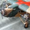
JWM Posted March 31, 2020 Author Share Posted March 31, 2020 I added decks and put some epoxy resin glue on joints mare as a filler and also to make stronger a bit As you see some decks I put on left some on right halves. This gives that both are really stiff. Moreover, you can set it together without any glue now I turned to do tail. After some sanding it looks almost ready Maybe I already told that, that I sanded a bit too high panel lines and rivets. I do not want to scribe it as it it enough that I will have to do that on fuselage. I am a bit affraid if I will be able to do that really good. We will see. Problem is with length of them. I engraved surface on some models, but they were small. ... I worked on props and engines. The exhaust pipes are partially from Sunderland kit, partially from a sprue (Academy Catalina has nice diameter in frame with radars) Then with putty I 've made cowling-pipe connections. I finished construction of props adding pitch change mechanism elements. I added the construction elements in cowling and glass on landing lamp, not finished yet sanding. The props are smoothly rotating! The brass tubes are axis. To do those small cylindrical elements I used "secret weapon" which I have found among tools used by Mrs JWM - the special tool for making holes in leather belts: As you see it is has six tubular knives (tubes with sharp edge), you may chose desired (OK, one of six existing) diameter and press on a plastic sheet of given thickness. One can see above nice "pills" produced. It is also suitable to cut out circular decal from a sheet of given colour. So now I keep in memory where my wife store it.... I turned to measure where windows has to cut and a problem appeared. It is that I made mistake in position of one frame, and it would made impssible to place one window in right position. So I had to rome parts of that one frame, and I heve to think what t do with it. Maybe I will do nothing, and imply the inside will be with a fault a bit difficult to notice in fact. Since I am doing a military variant (still not sure which one - the RAF one from Norwegian campaign or from RAAF?) and nothing is known about the inside of cabins I think I will ust left it i interior green. I asked today question on WWII section of BM and I've received answer, that almost for sure all luxury equipment was romeved from inter space when machines were impressed to military use. To be continue Regards J-W 7 Link to comment Share on other sites More sharing options...
AdrianMF Posted March 31, 2020 Share Posted March 31, 2020 Looks great. I like the engines and propellers, complete with the cowling support struts. Regards, Adrian 1 Link to comment Share on other sites More sharing options...
Shorty84 Posted March 31, 2020 Share Posted March 31, 2020 Hi J-W, that is a build to my taste. Quite a job creating an Empire boat but it looks you have everything under control. An RAAF machine would definitely get my vote. Cheers Markus 1 Link to comment Share on other sites More sharing options...
JWM Posted April 1, 2020 Author Share Posted April 1, 2020 Today I worked a bit on tailplane. I added central part glued from many thin layers (sheets of 0.25 mm thickness) Then I filled it with Tamiya filler In paralel I started to work on Italeri Sunderland Mk I. Yesterday I filled up all surface details, which are unrealistic in this model. Todsy I ssnded all them so the work on Empire slowed down. However I determined positions of all windows and frilled openigs as well as cut the big squares on right half of fuselage (I've got fuselage with openings on left half made already). Here is comparison with Sunderland To be continued Regards J-W 7 Link to comment Share on other sites More sharing options...
P.1127 Posted April 1, 2020 Share Posted April 1, 2020 Enjoying this a much as I enjoyed your Boeing 314 build. The comparison shown of the Sunderland and Empire fuselages is enlightening. Jack 1 Link to comment Share on other sites More sharing options...
JWM Posted April 3, 2020 Author Share Posted April 3, 2020 Many thanks P.1127 (Kestrel?) Time for big windows. I am going to use technique tested on mentioned by @P.1127 in WIP thread on Boeing 314 build. I glued relatively large clear pieces of plastic sheets and then using mask I will do separate windows. Then from outside I paint it with inner green, just to have this colour when looking from inside It gaves that effect Please note on above that I glued in inforcements in keel. This is bacause I have notice, that bteween frames the surface of hull bacames concave. So along the keel I gave those reinforcement. The cockpit interior is a bit started. From outside I pot on surface of thase windows a thin layer of putty, to hide the edges between the clear element and vacu surroundings. To be continued Regards J-W 8 Link to comment Share on other sites More sharing options...
AdrianMF Posted April 4, 2020 Share Posted April 4, 2020 Great progress on a dodgy vac! I said you’d probably be finished before I had my fuselage halves together and it looks like I wasn’t wrong. Looking forward to more. Regards, Adrian 1 1 Link to comment Share on other sites More sharing options...
JWM Posted April 4, 2020 Author Share Posted April 4, 2020 Hi, After sanding many masks on large windows did not survived. I had to replace them, since they will be useful to protect windows during final sanding, painting and varnishing. The windows are 6 per 8 mm but with rounded corners. I have used Tamiya 6 mm width tape and made rectangulars (on alu plate) Then I rounded corners with a sharp knife] They are not ideal, but this is what I was able today o do. I put them, on positions Please note drilled out two more windows near leading edge of wings. I tested if the open is still small enough to use clearfix to form window The test went OK (two most upper side of airlne Cheers J-W 5 Link to comment Share on other sites More sharing options...
janneman36 Posted April 4, 2020 Share Posted April 4, 2020 Great job you are doing sofar👍 Regarding those windows and putty on regular paper tape or washi tape, that aint working..you have to use a plastic type of tape for that as the solvent eats it’s way through the paper... And boy how did I learned that😉 cheers, Jan 1 Link to comment Share on other sites More sharing options...
JWM Posted April 5, 2020 Author Share Posted April 5, 2020 Thank you! Today I completed the work on cockpit. It it a bit what if - the only sure stuff I had was a look of instrument pannel and pilot desk, loke here The position of radio operator is taken from this drawing (fact that he was sitting back to flight) The instrument pannel is made out from decal given by Italeari in Sunderland (they are two provided: one to be done just as decal, second as a background to PE instrument pannel). The original decal was cut and re-arranged. I added control handles to engines, pedals and control wheels (the lates from Airfix Sunderland) I added belts done from Tamiya tape (coloured) So this is was the moment to close fuselage...(as you can see the safety belts are added just before doing it...) Let left it over a day... Regards J-W 7 Link to comment Share on other sites More sharing options...
LorenSharp Posted April 5, 2020 Share Posted April 5, 2020 Excellent job so far, Sorry I got to this party late. Vacs are a delight to watch unfold, especially if there is conversion involved. 1 Link to comment Share on other sites More sharing options...
Vesa Jussila Posted April 5, 2020 Share Posted April 5, 2020 Good progress! 1 Link to comment Share on other sites More sharing options...
JWM Posted April 6, 2020 Author Share Posted April 6, 2020 Thnaks for comments! The tail. It is glued together: Just to measure how it fits: Not bad... But first I have to get smooth surface on fuselage and then I will scribe the pannel lines. After it I can go to work on tail, but first I think I will attache wings to get right angles. Sanding of fuselage is progressing, second time some putty is applied. From bottom it was necessary to fill some concaving spaces Also the top and nose requires some "fine tunning" That its for today... Regards and keep COVID away from you! J-W 9 Link to comment Share on other sites More sharing options...
stevehnz Posted April 6, 2020 Share Posted April 6, 2020 I'm really like what you're doing with this J-W, I'd love to do one of the TEAL Empires one day, this is showing a great example. Take care Steve. 1 Link to comment Share on other sites More sharing options...
JWM Posted April 7, 2020 Author Share Posted April 7, 2020 Today was time for canopy... The original Airfix Sunderland is "almost" good, maybe because it is not so similar to the proper Sunderland one. Anyway - in general it fits, but is is too short.I decided to use it but to extend it. First I cut out the last window section I used a permanent marker (black) to paint both bottom of canopy and the section of vacu fuselage. The white plastic from fuselage could be then seen. An dthe paining of canopy prevents silvering of the edge of canopy Then I used a small plastic dish, a kind of disposal used It has curved walls and it is made put of styrene I cut out the windows from it, glued using Clearfix by Humbrol The roof in empire as a airliner is metal, so i can use normal puttty to make smooth transition to fuselage A bit more putty Tomorrow sanding and next corrections... Regards J-W 8 Link to comment Share on other sites More sharing options...

Recommended Posts
Create an account or sign in to comment
You need to be a member in order to leave a comment
Create an account
Sign up for a new account in our community. It's easy!
Register a new accountSign in
Already have an account? Sign in here.
Sign In Now