gingerbob Posted February 3, 2020 Share Posted February 3, 2020 I just got the (ten year old) "new tool" Revell Mosquito, and while perusing the sprues I noticed some PR camera parts- a lone camera and a pair on a rack. Made a mental note... 1 Link to comment Share on other sites More sharing options...
Toryu Posted February 3, 2020 Share Posted February 3, 2020 What a nice detail work on that scratch-built camera! You need to leave the window open for camera maintenance to display it - maybe hinge the panel. 1 Link to comment Share on other sites More sharing options...
ColFord Posted February 3, 2020 Share Posted February 3, 2020 Lovely work on that camera installation. Toryu, no panels to hinge. Access to the oblique camera installation was via the open cockpit canopy for minor stuff, otherwise removal of the rear perspex quarter windows (or sheet metal equivalent on one side in this case) to access the camera and lens and associated radio gear tucked further behind them in the fuselage. Link to comment Share on other sites More sharing options...
ragnarec Posted February 4, 2020 Author Share Posted February 4, 2020 Thank you @Andwil, @Biggles87, @gingerbob and @ColFord for encouraging comments! I'm not new to this kind of detailing work, but still find is fiddly and time consuming. But it is rewarding, too! I hope that at least something will be visible through the starboard quarter window. Link to comment Share on other sites More sharing options...
ragnarec Posted February 4, 2020 Author Share Posted February 4, 2020 (edited) The vacuum formed replacement canopy arrived earlier than expected. I have decided to discard my home made starboard rear window and replace it by the corresponding part of the Falcon Clear Wax canopy. The Falcon canopy includes part of the fuselage, which makes it easier to be get a nice interface between the canopy and the fuselage. The required parts of each fuselage half have been removed, but some more trimming of both canopy and fuselage is needed to get a nice fit. Edited March 5, 2020 by ragnarec 10 Link to comment Share on other sites More sharing options...
ColFord Posted February 5, 2020 Share Posted February 5, 2020 Ragnarec, That is looking very good. Like how the Falcon Clear Vax canopy includes the fuselage section, always one of the fiddly bits when building the AM kit using the kit tansparencies. FYI, Imperial War Museum has recently added some more early Mustang photos, this time aircraft of No.170 Squadron RAF, during a visit by a senior Army officer in November 1942, and a couple include reasonable close ups of the early 'funnel' style camera mount as featured on your subject aircraft. Have a look at CH.25229 and CH.25230. Also good as they show some of the areas of wear and tear on the paintwork around the cockpit. 2 1 Link to comment Share on other sites More sharing options...
BlueNosers352nd Posted February 5, 2020 Share Posted February 5, 2020 15 hours ago, ragnarec said: The Falcon canopy includes part of the fuselage, which makes it easier to be get a nice interface between the canopy and the fuselage. I wish all early Mustangs were done like that. Always hate trying to fit those windows in. 2 Link to comment Share on other sites More sharing options...
Andwil Posted February 5, 2020 Share Posted February 5, 2020 9 hours ago, BlueNosers352nd said: I wish all early Mustangs were done like that. Always hate trying to fit those windows in. P-40s also. AW 2 Link to comment Share on other sites More sharing options...
ragnarec Posted February 6, 2020 Author Share Posted February 6, 2020 On 05/02/2020 at 03:30, ColFord said: FYI, Imperial War Museum has recently added some more early Mustang photos, this time aircraft of No.170 Squadron RAF, during a visit by a senior Army officer in November 1942, and a couple include reasonable close ups of the early 'funnel' style camera mount as featured on your subject aircraft. Have a look at CH.25229 and CH.25230. Also good as they show some of the areas of wear and tear on the paintwork around the cockpit. Interesting photos. There seems to be some kind of rubber gasket that apparently was used to fill the gap between the funnel hole and the camera lens. The photos also show that I have made the funnel a bit too deep on my model. Ragnar Link to comment Share on other sites More sharing options...
ragnarec Posted February 14, 2020 Author Share Posted February 14, 2020 (edited) I've finally managed to put some colours into the cockpit. I have used an old tin of Humbrol 151, a somewhat bright interpretation of Interior Green. I have no paint that equals Bronze Green, and have used Vallejo Air 71013 (Yellow Olive) in stead for the seat and the instrument panel glare shield. No too far off, I hope. The home-made seat armor has been painted Tamiya XF-81 Dark Green. Camera and mounting a light grey colour. Radio and instrument panel Tamiya Nato Black. AM's cockpit is quite nicely detailed, but I am uncertain how accurate it is. It does not compare well with cockpit photos of preserved P-51A/F-6B museum exhibits. Next comes some more detail painting and a bit of weathering. Hopefully I will be able to glue the fuselage together in a not too distant future! Ragnar Edited March 5, 2020 by ragnarec 6 Link to comment Share on other sites More sharing options...
Johnson Posted February 14, 2020 Share Posted February 14, 2020 2 hours ago, ragnarec said: I have used an old tin of Humbrol 151, a somewhat bright interpretation of Interior Green. I always liked this, but how it compares to the real thing, I couldn't say. Replaced by Humbrol 226? Continuing to enjoy your great build! 1 Link to comment Share on other sites More sharing options...
ragnarec Posted February 19, 2020 Author Share Posted February 19, 2020 (edited) The camera compartment is finished, and the cockpit painted and weathered. Finally ready for gluing the fuselage together. Ragnar Edited March 5, 2020 by ragnarec 6 Link to comment Share on other sites More sharing options...
Johnson Posted February 19, 2020 Share Posted February 19, 2020 Lovely work Ragnar, shame to close it up, but has to be done. But what about the little satchel in the lower half? Should it be leather? Link to comment Share on other sites More sharing options...
ColFord Posted February 19, 2020 Share Posted February 19, 2020 Looking good Ragnar, but one little thing to add before you close it up. The Air Ministry Type 35 camera control box on the cockpit floor just to the left of the base of the control column. (If you google Type 35 camera control, it will bring up photos of the unit.) See location #37 on the cockpit photo from the pilot's manual here: https://www.britmodeller.com/forums/index.php?/topic/44133-a-few-mustang-mki-questions/page/6/ Regards. 1 Link to comment Share on other sites More sharing options...
ragnarec Posted February 20, 2020 Author Share Posted February 20, 2020 (edited) 20 hours ago, Johnson said: Lovely work Ragnar, shame to close it up, but has to be done. But what about the little satchel in the lower half? Should it be leather? Thanks for the compliment, Charlie! I've not forgotten the satchel, just ignored it. It will be completely hidden beneath the camera shelf. Eagle-eyed observers might have noticed that the battery shelf is missing. It should have been there (I assume), but has been omitted because it would have been impossible to see on the finished model. 20 hours ago, ColFord said: Looking good Ragnar, but one little thing to add before you close it up. The Air Ministry Type 35 camera control box on the cockpit floor just to the left of the base of the control column. (If you google Type 35 camera control, it will bring up photos of the unit.) See location #37 on the cockpit photo from the pilot's manual here: https://www.britmodeller.com/forums/index.php?/topic/44133-a-few-mustang-mki-questions/page/6/ Thanks for more info, Colin! I have completely missed the photos in the link. There is a wealth of info on the Mustang I here on Britmodeller, but is scattered all over the place, which makes it easy to miss out some of it. I've already glued together the fuselage, but I think it will be straight forward to it put in the camera control box anyway. The pictures from the Pilots Manual confirm that the sidewall detail of the AM kit is pretty fictitious. But I have decided to just live with it in this case. Ragnar Edited February 20, 2020 by ragnarec 1 Link to comment Share on other sites More sharing options...
Biggles87 Posted February 20, 2020 Share Posted February 20, 2020 I see that you follow my philosophy of “ if you can’t see it on the finished model, don’t fit it, ” regarding the battery shelf. 😀 John 1 Link to comment Share on other sites More sharing options...
ragnarec Posted February 21, 2020 Author Share Posted February 21, 2020 (edited) The camera control box has been made and mounted into the cockpit. Regarding the sidewall detail, I think I have glued the two levers on the port side in the wrong location. I have an early boxing of the AM Mustang, with very rough assembly instructions and it was less than obvious where the levers were supposed to go. I consider to break them of and relocate them. Next job is to reconstruct the carburettor intake housing. I've understood that late Mk Is and Mk IAs had provision for mounting a Vokes filter in the air duct, and that the housing as a result was broader than on early Mk Is. But not quite as fat as on the A-36 and later variants. Problem is that I have not been able to find photos that show the resulting shape. Suggestions, anyone? Anyway - I have started by plugging the hole in the nose by a flat piece of plastic. I intend to use the provided intake front, slight reshaped, and build up the rest of the housing from stock sheet. Ragnar Edited March 5, 2020 by ragnarec 7 Link to comment Share on other sites More sharing options...
ColFord Posted February 21, 2020 Share Posted February 21, 2020 Ragnar, have a look at the previous page to that discussion/thread I linked to here on Britmodeller in my last reply, in particular post #106 by Troy which shows some top down views of the intake trunking on early Mustangs. Further down on that page are some technical diagrams from the Erection and Maintenance Manuals of the intake arrangements. Your Type 35 camera control unit looks good!! 1 1 Link to comment Share on other sites More sharing options...
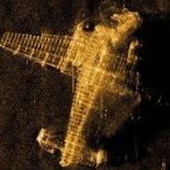
gingerbob Posted February 23, 2020 Share Posted February 23, 2020 Here's a shot of the later intake. Now, this is a test/development aircraft, so it may not be typical. (Note that you can supersize it.) Link to comment Share on other sites More sharing options...
ragnarec Posted February 23, 2020 Author Share Posted February 23, 2020 (edited) On 21/02/2020 at 08:38, ColFord said: Ragnar, have a look at the previous page to that discussion/thread I linked to here on Britmodeller in my last reply, in particular post #106 by Troy which shows some top down views of the intake trunking on early Mustangs. Further down on that page are some technical diagrams from the Erection and Maintenance Manuals of the intake arrangements. Thanks for info! Very useful images. On 23/02/2020 at 19:42, gingerbob said: Here's a shot of the later intake. Now, this is a test/development aircraft, so it may not be typical. (Note that you can supersize it.) Thanks! Again, a very useful image. Same aircraft as in one of the images @ColFord referred to. I have made a start. I thought is should be a fairly easy task, but have struggled to find a good approach. Which means that I have done things overly complicated. But hopefully I'll get there in the end. Ragnar Edited March 5, 2020 by ragnarec Link to comment Share on other sites More sharing options...
ragnarec Posted February 26, 2020 Author Share Posted February 26, 2020 (edited) Some more work on the carburettor intake. After a bit of Milliput and some sanding I put on a coat of grey primer to see how things looked. A bit fat may be, and not 100% symmetric. A bit more sanding will be required. Ragnar Edited March 5, 2020 by ragnarec 6 Link to comment Share on other sites More sharing options...
gingerbob Posted February 28, 2020 Share Posted February 28, 2020 Nice sculpting! 1 Link to comment Share on other sites More sharing options...
ragnarec Posted March 4, 2020 Author Share Posted March 4, 2020 (edited) Work continues on the airframe. As usual, I tend to do things more complicated than necessary. If mounted as advised by AM, the insert behind the radiator will create a recesses ahead of the tail wheel well. I don't think that is correct, and I chose to mount the insert so that the aft end got in line with the fuselage underside. The problem with this is that the insert has a curved profile, while the aft fuselage is flat. I believe that it should be curved, so the profile was built up with Milliput and sanded to shape. The photo below also shows that I have sliced the tail wheel leg in two, and only mounted the top section to the fuselage. This is to avoid the leg coming in the way for the required sanding etc. I have also made the radiator flap significantly more pronounced than the faint lines provided in the kit. The aft end has been temporarily cut off in order to make it easier to get a nice, straight aft edge. Oh, well... Things look more promising after a coat of primer. First time I have used the "One Shot Primer" from Ammo, and I really like it. Water based, but still takes wet sanding really well. I had some troubles getting the wing and nose inserts to fit 100%, and had to resort to Milliput and a lot of sanding in order to smooth things out. The nose insert was really a waste of effort, as I already had the required nose holes with the A-36 base kit. All the nice panel and rivet detail provided by Ultracast got lost in the sanding. I had to be really careful when sanding around the wing inserts to avoid damaging the delicate gun port detail. The picture below also shows that I have built up the radiator flap a little with Milliput in order to simulate a slightly lowered flap. Ragnar Edited March 5, 2020 by ragnarec 3 Link to comment Share on other sites More sharing options...
Johnson Posted March 4, 2020 Share Posted March 4, 2020 47 minutes ago, ragnarec said: As usual, I tend to do things more complicated than necessary. I should hope so! Your last two images didn't show, might be me, but you may want to check? Cheers, Link to comment Share on other sites More sharing options...
Andwil Posted March 4, 2020 Share Posted March 4, 2020 I’m only getting flashing grey squares instead of pictures. AW Link to comment Share on other sites More sharing options...

Recommended Posts
Create an account or sign in to comment
You need to be a member in order to leave a comment
Create an account
Sign up for a new account in our community. It's easy!
Register a new accountSign in
Already have an account? Sign in here.
Sign In Now