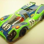
Jo NZ Posted January 4, 2020 Share Posted January 4, 2020 (edited) Bloody Mary is a hillclimber, built in the UK by John and Richard Bolster in 1929, when they were both schoolboys. It has a wooden (ash) chassis and was originally powered by a single J.A.P. V-twin of 750cc. Through the years, pre-war, it was refitted with bigger engines and ended up with two 1000cc J.A.P. KTOR V-twins, mounted in tandem. It competed until 1959, when it was put on display at the Montagu Motor Museum - and it's still there. It appears these days at events like Goodwood - the picture below is a from recent visit. Edited January 4, 2020 by Jo NZ Auto correct is far too clever for it's own good 7 Link to comment Share on other sites More sharing options...
Jo NZ Posted January 4, 2020 Author Share Posted January 4, 2020 The engines used in the final version, the JAP (for J.A. Prestwich) KTOR engine are more usually found at the front end of the Morgan 3 wheeler or mounted in a Brough Superior motorbike. It can be easily recognised by the external ohv valve springs. Luckily there are still drawings available for most of the engine (only because the microfilms were found in a gutter!) so I started by trying to make a cylinder barrel. The fins are a problem (getting them deep enough) but I could use a slitting saw on a rotary table, which would take forever (four barrels to make!). I tried a shorter slot using a lathe tool. I'll try it in place to see whether the fin depth is going to be seen. Here's the engines in situ And the trial cylinder - note that I miscalculated the pcd of the head bolts, so there are grooves down the bottom of the cylinder.... Chassis - I found some cedar of the right size (it scales out to about 3.75" by 1.8") and used brass sheet for the corner gussets The front springs are quarter elliptic and cord wrapped The leaves are cut from 0.4mm brass sheet, the wrapping is crochet cotton (found in the sewing box). I discovered on about the fifth look at the photo (after I'd wrapped it of course) that I'm short by one leaf. There should be another long leaf on top of the one with the eye.... Front spring mount. Not the most common type! The parts The bit that looks like a boat and the slotted T are silver soldered to make the bottom clamp plate. Everything seems to hang off this, which is why I've silver soldered it This bracket is important as it is the sole support for the friction damper/bottom radius arm, the hydraulic damper and the brake lever I made some M1.4 threaded rod to hold it all together. The rods are soft soldered into the bottom clamp plate 30 Link to comment Share on other sites More sharing options...
JeroenS Posted January 4, 2020 Share Posted January 4, 2020 Your chassis is beautiful. This should be interesting, I'm in. Link to comment Share on other sites More sharing options...
stevehnz Posted January 4, 2020 Share Posted January 4, 2020 I'm liking the look of this Jo, it's tech I can get my head around. Carry on please. Steve. Link to comment Share on other sites More sharing options...
harveyb258 Posted January 4, 2020 Share Posted January 4, 2020 OOOOOHHH YES!!!! Now we're talking.... Count me in. 1 Link to comment Share on other sites More sharing options...
Codger Posted January 4, 2020 Share Posted January 4, 2020 What could 'schoolboys' know about Bloody Mary ???? Frightening ! Jo so good to see you back in action. You lot of scratchbuilders here are the ultimate level of modeling for us all to learn from and enjoy. Like candy to children, your thread will draw all those talented guys (already here!) to share and explain. Carry on ! 1 Link to comment Share on other sites More sharing options...
Fastcat Posted January 4, 2020 Share Posted January 4, 2020 What a great choice. An amazing performance from a really home-made car. Just crying out to be modelled and something you won't see from any of the kit makers. Dave 1 Link to comment Share on other sites More sharing options...
PROPELLER Posted January 4, 2020 Share Posted January 4, 2020 Great choice indeed Jo... And great skills too, I do love that! Dan. Link to comment Share on other sites More sharing options...
Jo NZ Posted January 5, 2020 Author Share Posted January 5, 2020 Thanks for all the kind words! I thought as this was a special, and home built, it would be fairly simple to replicate. However as it's been modified over the years it's got quite complex and in some places quite crude. That points to a lot of fabrication and not much machining. I suppose one day I will learn how to cut or file in a straight line 😧 I'm going to get lots of practice. Although I took about 250 photos of BM in August last year, it's still not enough. Progress is necessarily slow as I need to find references for various commercial parts used - for example it took about an hour and a half on the net just to find the diameter of an Austin 7 kingpin... It also doesn't help when John Bolster (he wrote the Profile on BM) says he bought the steering box second hand but doesn't have a clue where it came from! He does quote the rear axle size as 1.5" and from that I'm estimating that the front axle is 1" diameter. Thats why I wanted to know the size of the kingpin, so I can check it out. Details I'm after at the moment, if anyone has them: Austin 7 front hub, wheel (19") particularly the rim profile, 19" Rudge wheel and hub (rear), and the Sturmey Archer motorcycle gear box as fitted to the Brough Superior (and many other bikes...) TIA Jo 1 Link to comment Share on other sites More sharing options...
Jo NZ Posted February 8, 2020 Author Share Posted February 8, 2020 The chassis is painted and the springs are wrapped - along with the knot on the nearside spring The front axle is a tube with caps that are machined square and drilled to accept the kingpins. I've made mine vertical, I've seen drawings with the kingpins vertical and also with positive or negative camber. It's easier if they start vertical, I can set the camber on the hub The brackets to attach the springs and lower arms to the axle are fairly complex. Here's where I am so far... 7 Link to comment Share on other sites More sharing options...
Codger Posted February 8, 2020 Share Posted February 8, 2020 You could build a full-size real one with the same amount of effort (and tools) as 1/8 scale, Jo. This has that wonderful 'home-made, hardware store' look. And terrifying to drive I'll bet.... Link to comment Share on other sites More sharing options...
Sabrejet Posted February 8, 2020 Share Posted February 8, 2020 Following this with interest: it's not often that one sees a proper hill climber in model form (in fact I can't think of another). 👍 Link to comment Share on other sites More sharing options...
ElectricLightAndy Posted February 8, 2020 Share Posted February 8, 2020 Beautiful workmanship there dude, I'm sure you are putting much more thought into this build than there would've been originally! Andy Link to comment Share on other sites More sharing options...
Jo NZ Posted February 8, 2020 Author Share Posted February 8, 2020 35 minutes ago, Black Knight said: What do you want to know about the Austin 7 front stub axle & hub. I'll not get to my A7 until Thursday I think I’m ok with the hub, from the outside they all look the same. What I can’t find is a cross section of the wheel rim. Can you help? It’s a 19 inch rim. Link to comment Share on other sites More sharing options...
kpnuts Posted February 9, 2020 Share Posted February 9, 2020 Great job so far, highly skilled craftsman. Link to comment Share on other sites More sharing options...
Jo NZ Posted February 10, 2020 Author Share Posted February 10, 2020 I needed to get the clamps precise as they have to match, hence the milling. Starting to free the clamps from the channel The first clamp pair Spring to axle. Bolts are 00-90 to the axle and M1.0 for the clamp 5 Link to comment Share on other sites More sharing options...
Pete in Lincs Posted February 10, 2020 Share Posted February 10, 2020 Some lovely (not so) micro engineering going on here. Good luck with the voyage, I'll drop by from time to time. BTW, we had J.A.P. engines on certain Aircraft ground support equipment years ago. Never easy to start! Link to comment Share on other sites More sharing options...
Bandsaw Steve Posted February 10, 2020 Share Posted February 10, 2020 Always enjoy watching a good scratchbuild me! 👍😀 Link to comment Share on other sites More sharing options...
Jo NZ Posted July 11, 2021 Author Share Posted July 11, 2021 (edited) It's over a year! Phew! Who knew that moving to a supposedly perfect house would involve so much work..... So, new house, new workshop, new (to me) lathe (1983 Emco compact 8 ) and I've started on BM again. First (don't laugh) the cockpit floor The wheels are from Shapeways, actually dragster wheels and not quite the size they say they are - they work out at 18 1/2" instead of 19". They will do for now, and give me an idea how it will look. The jig positions the chassis at the correct angle - useful when fitting the floor, as it's parallel to the road. Pedals (No tittering again please) Fitted And painted, also the first of the rear springs As I'm concentrating on the rear axle, I needed to make the chain sprocket. Chain in this size is difficult to come by so I'm using Tamiya 1/6 motorbike chain - it's the closest I can find. I made the sprockets the same diameter as the originals, but because of the chain pitch difference they will have a different number of teeth. There are lots of sprockets to make - engine 1 to engine 2, (2) engine 2 to the gearbox (2) and the gearbox to the final drive (2). Not to mention the magneto drives which need another 4 sprockets.... I started on the smallest sprocket - less work if it goes wrong. On the 3rd try I got a work able sprocket, after trying various cutters and files. Here's the final drive sprocket being machined And all the drive sprockets Proof that the chain fits, and another shot of the gearbox cluster with clutch I can't avoid it much longer. To make the crankcases and gearbox I'm going to need a 3d printer... looking at the Elegoo Mars 2 Pro. But for now I need to finish the back axle! Edited July 11, 2021 by Jo NZ Emojis. Too clever by half 11 Link to comment Share on other sites More sharing options...
Sabrejet Posted July 11, 2021 Share Posted July 11, 2021 Lovely to see this on the go again: some lovely work here 1 Link to comment Share on other sites More sharing options...
JeroenS Posted July 12, 2021 Share Posted July 12, 2021 Good to have you back Jo 🙂 I recently moved house as well and yes it cuts down on modelling time! 1 Link to comment Share on other sites More sharing options...
Jo NZ Posted August 17, 2021 Author Share Posted August 17, 2021 I made the brake drum and axle clamp for the rear drive sprocket and assembled them It's been too cold to work in the back of the garage, so it was time (finally) to get a 3d resin printer. A member of a different forum saw my plea for help for information on the J.A.P. KTOR engine, and supplied a nearly complete 3D model. Here are the basic components, printed to 1/8 scale And assembled Now I can start to work out the engine supports to the chassis. Until I had a really good look at the photos I hadn't realised that the rear engine is an upright "V", but the front engine has one cylinder vertical. The rough position is like this 7 Link to comment Share on other sites More sharing options...
Will Vale Posted August 17, 2021 Share Posted August 17, 2021 Ahah, you're now the terrifying wave of the future, churning out model bits from the primal ooze of creation. Looking lovely thus far! NB: You probably know this, but in terms of other hill climbers there was a dieselpunk-esque kit from Industria Mechanika called the Estafette which was heavily based on a JAP-engined racer. I think it's a GN special? Tiny scale though. https://industriamechanika.com/shop/land/26-her-majesty-s-estafette-.html https://en.wikipedia.org/wiki/GN_(car) Cheers, Will 1 Link to comment Share on other sites More sharing options...
Redstaff Posted August 17, 2021 Share Posted August 17, 2021 Wow The attention to detail and skills on show here are amazing Looking forward to more instalments Ian 😁 Link to comment Share on other sites More sharing options...
Jo NZ Posted January 23, 2022 Author Share Posted January 23, 2022 There's been a slight delay while I learnt to use Fusion360 (my fourth CAD program, I can nearly do without the pills now). I decided that some parts were just too difficult for me to make in brass. I have stared at the Armstrong lever arm damper for hours trying to figure it out. Anyway it seems to work in 3D! Here's the first iteration, the brass hexagons top and bottom will be added using cut down 0-80 and 00-90 hex head screws. 4 Link to comment Share on other sites More sharing options...

Recommended Posts
Create an account or sign in to comment
You need to be a member in order to leave a comment
Create an account
Sign up for a new account in our community. It's easy!
Register a new accountSign in
Already have an account? Sign in here.
Sign In Now