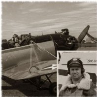
Army_Air_Force Posted December 2, 2019 Share Posted December 2, 2019 (edited) This is a project that was started in July and just completed a few days ago. It was ordered as a present for the pilot of the fullsize Jungmann and so I've kept details of the model off the net until he received the model over the weekend just gone. The picture below shows the fullsize example, not long after arriving in the UK from Germany. Over the winter, the owner is converting the aircraft to a fully aerobatic configuration, with an inverted fuel system and other changes. This is because he competes in international aerobatic competitions using the Aresti sequence of manoeuvres. The Aresti catalog is the Fédération Aéronautique Internationale (FAI) standards document containing the aerobatic manoeuvres permitted in aerobatic competition. It was upon arrival of the aircraft that I was brought into the equation. I was approached by friends of the pilot, to produce a model of his aircraft that he could use to plan and run through manoeuvres prior to taking to the air. The Revell boxing of the Jungmann was to be the basis of the aircraft, but there would be a number of changes along the way to try and make the model more durable. Edited October 23, 2020 by Army_Air_Force 4 Link to comment Share on other sites More sharing options...
Army_Air_Force Posted December 2, 2019 Author Share Posted December 2, 2019 (edited) So before the build began, I ordered up a few extra materials. An oak base, oak dowel, some 4mm stainless steel rod, and some brass tube and rod. Since the model was to be used for planning aerobatic manoeuvres, it would need a handle, preferrably along the centreline. A paper jig was made to show the bends needed to align the handle. Since I didn't want the rod to cut through the rudder, it was formed to drop out of the underside of the fuselage and back up to the centreline aft of the rudder. Edited October 23, 2020 by Army_Air_Force 3 Link to comment Share on other sites More sharing options...
Army_Air_Force Posted December 3, 2019 Author Share Posted December 3, 2019 (edited) In order to key the handle and provide some torque resistance between the handle and model, the end of the stainless rod was bent. To achieve this at such a sharp angle, it needed heating with a gas torch and then reheating after bending to help to reduce any stresses. The underside of the fuselage then needed cutting open to allow the rod to pass inside the fuselage. Edited October 23, 2020 by Army_Air_Force Link to comment Share on other sites More sharing options...
Army_Air_Force Posted December 4, 2019 Author Share Posted December 4, 2019 (edited) With the stainless rod nailed to the bending jig, the fuselage half was supported on scrap styrene, until the fuselage vertical centreline was half way up the stainless rod. The inside of the fuselage was roughed up and then some drops of cyano spotted in, then sprinkled with some milled fibreglass fibres. This would give the epoxy a good surface to key to, ensuring the handle was securely fastened. The epoxy was mixed with more milled fibres to create a thick goo which was pasted inside the fuselage. That was then weighted down over the stainless rod. Once completely dry, the nails were pulled out from around the stainless rod and the fuselage was lifted off the board. Further epoxy would be added around the joint before the fuselage was closed up. Edited October 23, 2020 by Army_Air_Force Link to comment Share on other sites More sharing options...
Army_Air_Force Posted December 5, 2019 Author Share Posted December 5, 2019 (edited) Can you tell what it is yet!! Almost at the point of making aeroplane noises and flying it around the workshop!! Step one for trying to improve the durability of the model was to ditch the plastic wing struts. Instead I'd be using brass tube. To locate and anchor the brass tube to the wing, I used some 0.5mm brass wire. This was formed into a shape that would glue to the inside wing skin and leave around half an inch sticking up towards the strut position. The wing was drilled for the wire and it was glued to the inside skin after roughing up the surface. Edited October 23, 2020 by Army_Air_Force 1 Link to comment Share on other sites More sharing options...
Antti_K Posted December 6, 2019 Share Posted December 6, 2019 Hello Stephen! I'm going to start my Jungmann project in the near future so I will look at this with great interest. A very nice idea to build an accurate model for Aresti exercises! What overall colour will you use; "Grau" or "Perlweiss"? Ullmann's book gives "Perlweiss" based on factory documents. However we have a set of original factory manuals here in Finland (Two Jungmanns were registered in 1938) and they say "Grau"... Cheers, Antti Link to comment Share on other sites More sharing options...
Army_Air_Force Posted December 7, 2019 Author Share Posted December 7, 2019 (edited) I worked from photos, so the grey was a primer that seemed a reasonable match based on pictures in bright light and shadows. Since the model itself wasn't being judged, only the flying of the fullsize, absolute accuracy wasn't a requirement. I don't even know if the fullsize example I was modelling was restored and painted with the correct factory colours. With the brass wires embedded in the wings, I turned my attention to the wing struts, interplane struts first. Brass tube is round in section and of course the wing struts weren't, so I needed a jig to flatten the tube into an elliptical section. This was done with two bits of smooth steel, a vice and the 0.5mm brass wire. The strut was cut slightly over length and a piece of the 0.5mm brass wire threaded through the middle. This would stop the tube from being crushed completely. The tube was then masking taped onto one bit of steel to keep it still and then both pieces were placed in the vice. After a few turns, the tube would rush no more and it was all taken apart to reveal a nice elliptical strut. Having the brass wire in the tube during crushing meant that the hole was maintained to allow the new strut to slide onto the wire in the wing. These would be glued with epoxy during final assembly. Edited October 23, 2020 by Army_Air_Force 2 Link to comment Share on other sites More sharing options...
Army_Air_Force Posted December 8, 2019 Author Share Posted December 8, 2019 (edited) The next stage was a jig for the cabane struts. I cleaned up the plastic parts and laid them on a piece off wood. Small wood strips were then glued either side of each strut and these would then hold the brass tubes in place for soldering. More brass tube was squashed into an elliptical section for these struts. 0.5mm brass wire was threaded through the struts and would form anchors to attach the brass structure to the styrene model. Two at the bottom are visible in this picture and would extend into the upper wing centre section. The other two are bent at 90 degrees and pass through the wooden jig. These would pass into the fuselage. Edited October 23, 2020 by Army_Air_Force 2 Link to comment Share on other sites More sharing options...
Army_Air_Force Posted December 9, 2019 Author Share Posted December 9, 2019 (edited) Once the cabane struts were all soldered up, they were removed from the jigs and were cleaned up with a file. They are seen here upside down, with the 90 degree bends in the 0.5mm wire going into the fuselage and the straight wire extending into the wing. I knew that a certain amount of assembly would take place after painting and decalling. The top wing would certainly need to wait. Unlike simple plastic struts, I couldn't make a simple glue joint at the end. To resolve this, I cut the centre wing section top skin out of the upper wing top skin. The outer panel top skins were glued to the wing underside, but the centre section was left off for now. This allowed access to the brass wires from the cabane struts so that in the later stages of assembly, the wing could be fitted, the wires bent over and glued before fitting the top skin of the centre section. The paint on that could be touched in as one of the last jobs. Edited October 23, 2020 by Army_Air_Force 5 Link to comment Share on other sites More sharing options...
Army_Air_Force Posted December 10, 2019 Author Share Posted December 10, 2019 (edited) The lower wing skins were joined next. The cockpit floor structure was also added. The port fuselage side had more epoxy and milled fibres added to the stainless handle and the internal fuselage structure was added to the side walls. The other side shows the milled fibres sprinkled onto drops of cyano to help the epoxy bond. Edited October 23, 2020 by Army_Air_Force 1 Link to comment Share on other sites More sharing options...
Army_Air_Force Posted December 13, 2019 Author Share Posted December 13, 2019 (edited) With the wing skins joined and the fuselage internal structure done, the fuselage was joined. Additional epoxy would be poured down the fuselage to bond the second half into the stainless steel handle. Joining of the lower wing to the fuselage came next. Edited October 23, 2020 by Army_Air_Force Link to comment Share on other sites More sharing options...
Army_Air_Force Posted December 14, 2019 Author Share Posted December 14, 2019 (edited) The next step on the fuselage was to add two further forward fuselage sections, the metal skins around the cabane struts. These pieces were drilled out to allow the 0.5mm brass wire pins on the struts to pass through to be glued on the inside. Here, one styrene section has been fitted and the first strut is trial fitted. Once both sides had been drilled, fitted and had time to harden, the model was trial assembled with the struts and upper wing. I was pleased that everthing fitted and lined up ok. Edited October 23, 2020 by Army_Air_Force 1 Link to comment Share on other sites More sharing options...
Army_Air_Force Posted December 15, 2019 Author Share Posted December 15, 2019 (edited) The 0.5mm brass wire was bent around the styrene fuselage side to allow it to be covered with epoxy to hold the struts in place. The wires through the upper wing would remain untouched until I was ready to attach the top wing. Next was the fairings between the struts, the instrument panels and the fairings over them. The engine had been made, but it would later turn out that it couldn't be fitted due to modifications inside the engine cowling to accomodate the two prop options. Edited October 23, 2020 by Army_Air_Force Link to comment Share on other sites More sharing options...
Army_Air_Force Posted December 20, 2019 Author Share Posted December 20, 2019 (edited) The elevators were joined to the tailplanes and the tailplanes themselves were drilled for a brass pin that would pass through the fuselage. Both sides were then jigged up and glued in place. Edited October 23, 2020 by Army_Air_Force 4 Link to comment Share on other sites More sharing options...
Pete in Lincs Posted December 20, 2019 Share Posted December 20, 2019 Well there's robust and then there is this model. Very impressive work. I look forward to the end result. And, I'd love to see the display. Link to comment Share on other sites More sharing options...
Army_Air_Force Posted December 21, 2019 Author Share Posted December 21, 2019 (edited) Thanks. There's a good chance I'll get to see what it's like from the cockpit next year! Before the cowling could be attached, the cabane struts would need gluing. The top wing was fitted to align the strut angles and epoxy added to the inside of the fuselage, over the brass wire pins. Once tacked in place with a small amount of glue, more epoxy was added with the fuselage on its side so the epoxy didn't run down into the bottom. Each side was done one at a time. As the model would be displayed on a base in a climbing pose, I decided that prop should really be turning. I don't like full plastic discs as they have no thickness to them, and really dislike etched brass blurs, so decided to have another go at something I tried on my daughter's Snoopy/Fokker DRI 3D picture. A 3mm thick bow-tie of clear acrylic was cut for the new prop. The rough blank was tapered in thickness towards the tips, but also had an angle of incidence sanded into the "blades". Here's the prop blank part way through the sanding to shape. Edited October 23, 2020 by Army_Air_Force Link to comment Share on other sites More sharing options...
Army_Air_Force Posted December 24, 2019 Author Share Posted December 24, 2019 (edited) First fine sand and polish of the prop. There were still a few nicks and scratches so the wet sanding continued. To hold the prop in place, but also allow for slight knocks, I decided to hold it in place on an M3 stud. To retain it, two M3 nuts were soldered together and epoxied into the front of the cowling. Edited October 23, 2020 by Army_Air_Force Link to comment Share on other sites More sharing options...
k5054nz Posted December 26, 2019 Share Posted December 26, 2019 What a fantastic idea for a tool, and a fascinating build process too. Thanks for sharing this with us, Stephen - I enjoy every update, 1 Link to comment Share on other sites More sharing options...
Army_Air_Force Posted December 26, 2019 Author Share Posted December 26, 2019 (edited) After a dip in "Future", I still wasn't happy with the prop, either scratches showing or Future pooling, so it was all wet sanded again! Due to the M3 nuts inside the front of the cowling, the scale engine wouldn't fit. It wasn't going to be seen anyway so left it out. To simulate the engine through the cooling hole in the front, I glued in a piece of M3 studding, its threads looking like cylinder cooling fins. Edited October 23, 2020 by Army_Air_Force 1 Link to comment Share on other sites More sharing options...
Army_Air_Force Posted December 28, 2019 Author Share Posted December 28, 2019 (edited) I was quite pleased with the look when the cowl was turned around. With that done, the full cowl was assembled and then attached to the front of the aircraft. With the cowl and rudder attached, the airframe was given a coat of primer. Edited October 23, 2020 by Army_Air_Force 1 Link to comment Share on other sites More sharing options...
Army_Air_Force Posted December 28, 2019 Author Share Posted December 28, 2019 (edited) The top wing was also primed everywhere except around the top centre section which wasn't yet fitted. Once that had dried, the cowl, cockpit doors, rear hatch and fairings were painted the darker grey. Edited October 23, 2020 by Army_Air_Force Link to comment Share on other sites More sharing options...
Army_Air_Force Posted December 29, 2019 Author Share Posted December 29, 2019 (edited) Landing gear upgrade next. The plastic parts were cut out and trimmed in order to use them to make the building jigs for the brass parts. The wood strips were cut to hold the brass rods together and to support them at the correct angles for the axles. The wood was tapered towards each solder joint to allow better access for the soldering iron. Edited October 23, 2020 by Army_Air_Force 2 Link to comment Share on other sites More sharing options...
Army_Air_Force Posted December 29, 2019 Author Share Posted December 29, 2019 (edited) Again using the plastic part to form a jig, the centre bracing of the landing gear was assembled. After a little soldering and a quick dress with a needle file, the beginnings of the metal landing gear was coming together. Edited October 23, 2020 by Army_Air_Force 3 Link to comment Share on other sites More sharing options...
Army_Air_Force Posted December 30, 2019 Author Share Posted December 30, 2019 (edited) The next delicate step was to solder the main legs to the cross brace and then add the rearwards centre bracing strut. The holes in the bottom of the wing were enlarged a little to make it easier to slot the assembled brass structure into place. After that was assembled, I cut some styrene triangles to fill in the gap between the legs. These were glued in place with cyano and then all the joints around the triangle filled and sanded a few times. Edited October 23, 2020 by Army_Air_Force 2 Link to comment Share on other sites More sharing options...
Army_Air_Force Posted December 31, 2019 Author Share Posted December 31, 2019 (edited) A gloss coat on the airframe was next, ready for the decals. They would need to be applied before the top wing was added. Since the model was going to be in custom markings, I had previously made a set of markings on my computer, prior to starting the model. The wings and fuselage parts were scanned with a flatbed scanner to give me an indication of the required size. The decal designs were printed in black and white on paper, cut out and offered up to the plastic parts to check on the sizes. On a previous project, I contacted a friend who could print ALPS type decals. He was in the middle of moving house and with all his gear packed away, he was unable to help me. That resulted in a search of the internet where I found http://www.precisionlabels.com/ here in the UK. John Peck who runs the business, was very helpful with advice on preparing the PDF graphics and printed the decals for my Broussard project. I contacted him again for the Jungmann, which also had some additional Broussard decals and also those for the Miles Messenger I was working on at the same time. They are fragile since the carrier film is very thin, but they settle over detais very well and can reproduce very fine, small text. Here's the sheet I designed after printing. I took the precaution of having extra sets of the decals in case of accidents during application. Edited October 23, 2020 by Army_Air_Force 3 Link to comment Share on other sites More sharing options...

Recommended Posts
Create an account or sign in to comment
You need to be a member in order to leave a comment
Create an account
Sign up for a new account in our community. It's easy!
Register a new accountSign in
Already have an account? Sign in here.
Sign In Now