Vulcanicity Posted June 6, 2020 Share Posted June 6, 2020 2 minutes ago, 71chally said: It's a shame that it looks like a Varsity isn't following, apart from the undercarriage, engine nacelles and the under fuselage gondola, are there any other differences between the two? I have a feeling the Varsity fuselage is substantially longer? Link to comment Share on other sites More sharing options...
TheyJammedKenny! Posted June 6, 2020 Share Posted June 6, 2020 8 minutes ago, TEXANTOMCAT said: Not worried about the engine with the massive spinners you won’t see much anyway! This is true. The real Valetta had an impeller to cool the Bristol Hercules' cylinder heads, just like the Noratlas. On the other hand, it would be nice to model this with the option of showing a bird with the spinners removed, as some did early in their career, due to spinner failures. I'm more concerned by what I see in the nose contours. The ogival curvature at the top (near the windscreen) seems excessive, and there's not enough curvature from the lower fuselage. I'm comparing it against drawings that I have. Link to comment Share on other sites More sharing options...
TEXANTOMCAT Posted June 6, 2020 Share Posted June 6, 2020 8 minutes ago, Vulcanicity said: I have a feeling the Varsity fuselage is substantially longer? Yes and the wings are bigger too I think so you’re looking at new fuselage, wings, canopy, undercarriage... basically a new kit If this sells well perhaps one will follow suit.. TT 1 Link to comment Share on other sites More sharing options...
TheyJammedKenny! Posted June 6, 2020 Share Posted June 6, 2020 Ok, I'm looking at the photos in Bill Overton's excellent book about the Valetta, and the nose of the example on the sprue looks more like photos of the real thing than the scale drawings, so I don't think we're far off here. The modeler may wish to tweak the shape a bit, but that's not a reason not to purchase. I'd still like one...and a Viking later. Alex T. 2 Link to comment Share on other sites More sharing options...
Mr T Posted June 6, 2020 Share Posted June 6, 2020 As John Aero would point out, a lot of published drawings are not accurate for a variety of reasons and so it would be no surprise if the nose drawings do not match photos or the kit. Looking forward to getting this kit as got to be easier than a Magna resin, at least it can be stuck together with something other than epoxy and superglue. 1 Link to comment Share on other sites More sharing options...
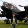
TheyJammedKenny! Posted June 6, 2020 Share Posted June 6, 2020 24 minutes ago, Mr T said: it would be no surprise if the nose drawings do not match photos or the kit. Indeed. The best resource is a photograph, such as this, from Valetta, copyright 1996 Bill Overton. Note the nose contours and compare them against the sprue shots. 2 Link to comment Share on other sites More sharing options...
Learstang Posted June 7, 2020 Share Posted June 7, 2020 (edited) Nice photograph of the Valetta - Shackletons also saw use from Labuan Island (Pula Labuan) during the Konfrontasi between Malaysia and Indonesia. Another occasion to have a Valetta next to a Shackleton, this time a FEAF Shackleton. It's hard to tell, but is that a Pembroke in the background? And the one on the extreme left - a Beaver? I'm starting to get an idea for a nice diorama of some post-war piston-engined RAF aeroplanes. Regards, Jason Edited June 7, 2020 by Learstang 1 Link to comment Share on other sites More sharing options...
TheyJammedKenny! Posted June 7, 2020 Share Posted June 7, 2020 Jason: Yes, that's a Pembroke in the background, and I think the plane on the extreme left is a Pioneer--but others can correct me. The nose butting into the foreground belongs to a Beverly. The Valetta is a feast for the eyes for those who love working in silver, white, and orange. Separately, I looked at photos of the air crew quarters at Labuan taken at the time. Not a bad place! 1 Link to comment Share on other sites More sharing options...
Aeronut Posted June 7, 2020 Share Posted June 7, 2020 Quote I think the plane on the extreme left is a Pioneer- Based solely on the tailwheel leg, its most definitely a Beaver. As a member of the HAAF engineering team its a component I have been in close contact with, up until the Covid lockdown. 1 1 Link to comment Share on other sites More sharing options...
janneman36 Posted June 11, 2020 Share Posted June 11, 2020 And available at the Aviationmegastore https://www.aviationmegastore.com/vickers-valetta-t-mk3-delivered-72143-valom-vaclav-lomitzk-8594054291436-vliegtuig-modelbouw/product/?action=prodinfo&art=169796 https://www.aviationmegastore.com/vickers-valetta-c-mk1-delivered-72142-valom-vaclav-lomitzk-8594054291429-vliegtuig-modelbouw/product/?action=prodinfo&art=167493 cheers, Jan 2 1 Link to comment Share on other sites More sharing options...
TOPGUN88 Posted June 11, 2020 Share Posted June 11, 2020 Looks a great deal better than the shake and bake maquette Viking kit. 1 Link to comment Share on other sites More sharing options...
thepureness Posted June 13, 2020 Share Posted June 13, 2020 On 6/11/2020 at 2:49 PM, janneman36 said: And available at the Aviationmegastore https://www.aviationmegastore.com/vickers-valetta-t-mk3-delivered-72143-valom-vaclav-lomitzk-8594054291436-vliegtuig-modelbouw/product/?action=prodinfo&art=169796 https://www.aviationmegastore.com/vickers-valetta-c-mk1-delivered-72142-valom-vaclav-lomitzk-8594054291429-vliegtuig-modelbouw/product/?action=prodinfo&art=167493 cheers, Jan Jan, can you show us what's in the box? Link to comment Share on other sites More sharing options...
janneman36 Posted June 13, 2020 Share Posted June 13, 2020 Just now, thepureness said: Jan, can you show us what's in the box? No I am sorry as I don’t have the kit myself...not my subject to build🤫 cheers, Jan Link to comment Share on other sites More sharing options...
Stilwell Posted June 13, 2020 Share Posted June 13, 2020 2 hours ago, thepureness said: Jan, can you show us what's in the box? The sprue shots in post 72 are representative of the C.1 boxing contents. The most obvious omission is the lack of fans to fit behind the propellers - an opportunity for the aftermarket people to produce a successor to Aeroclub set V077. I suspect, understandably, that the kit is based heavily on the C.2 aircraft VX580 in the museum at Flixton. Based on the photos elsewhere on Britmodeller: It is difficult to tell if the fans are actually fitted. But then, they aren't that easily visible when they definitely are fitted. So any lack of detail on the engine cylinders shouldn't be a problem. The kit includes the small intake fairings rear of the cockpit glazing; I'm not sure if most aircraft had these fitted, but they are easy to remove if references say your subject did not. The C.1 . C.2 style astrodome is provided, but you will need to make a hole for it if you want to fit it. I haven't tried yet, but it looks quite close to the bulkhead at the read of the cockpit. The kit does not have glazing for the clear panel on the rear door as seen on VX580. The fuselage roundel on VX580 on the starboard side occupies a location that most C.1 aircraft have an extra window. The extra window is provided, and the location is obvious from the panel lines on the outside, but the fuselage wall hasn't been thinned to aid removal. There is a thinned area to aid fitting of a narrow window above the main window line; VX580 has two narrow windows in this location, so making your own holes and glazing with clearfix may be required if you want to do this configuration. Any cabin interior will have to be provided by the builder; the photos I have seen suggest the color for the floor on the cargo aircraft is likely to be red / browl colour seen on the Flixton Museum website: https://aviationmuseum.site/index.php/2020/03/31/vickers-valetta-vx580/ I found that on mine, the orientation of how the main spar piece was fitted affected how well the fuselage halves aligned, so I swapped it around until they were able to line up well. The main lesson so far is that the identification of the part numbers on the instructions isn't very good. For the horizontal stabilisers, the location pins have different spacing on each side, so just match the two halves which have pins at the same spacing, and fit them onto the appropriate side of the fuselage, The sidewall panels in the under carriage bays have an aerofoil section that matches the wing, with the longer panels fitting on the inboard side - the panels should meet at the back end of the bay, and the slots half way along should line up to allow the web that the undercarriage actuating mechanism locates on to fit between them. The hub detail on the wheels differs on each side - I will have to confirm on the photos what the correct alignment is, as there is no guidance in the instructions. Jonathan. 2 Link to comment Share on other sites More sharing options...
TheyJammedKenny! Posted June 14, 2020 Share Posted June 14, 2020 Stilwell: Thanks very much for sharing your observations of the kit with us! It's funny that we should be talking about parts fit in the context of a Valom product, of all things, but I have the impression that this kit is Valom's attempt to reach out to a wider group of builders, and therefore most welcome. Based on a small sample size they already appear to be selling at a rapid pace. How are the wing halves? Is the alignment of the engine nacelles between upper and lower halves ok, or will this require some surgery? How is the alignment of the forward fuselage, particularly the nose? A curious public wants to know... Thanks, Alex. Link to comment Share on other sites More sharing options...
Stilwell Posted June 14, 2020 Share Posted June 14, 2020 4 hours ago, TheyJammedKenny! said: How are the wing halves? Is the alignment of the engine nacelles between upper and lower halves ok, or will this require some surgery? No surgery required. Line the tips up at the cut-out for the navigation light, and the nacelles are pretty good. The joint lines on the sides fo the nacelles may need a going over with a flexifile, but that would be as much to do with cleaning the joint as fixing the alignment. The alignement at the root trailing edge is close to spot on; the leading edge is less clean, but that is due to the shape of the edge of the lower wing half rather than an alignment issue. But I suspect that will go away in the process needed to get a clean joint of the wing to the fuselage. I was considering putting the wing uppers on first, then the lowers, to get a better alignment to the fuselage, but a dry fit suggests the wing spar may be a bit taller than needed, So I have stuck the wing halves together so I can judge how much needs to come off the spar. Then I think the inboard (root) edges of the wings will need some fettling to get a decent match to the sides of the fuselage. One thing to note is that, based on the photos from Flixton, the leading edges of the wings are not smooth, but have a several ridges running along them. I assume these are part of the de-icing system, but they are subtle enough that I won't be trying to mimic them. The fuselage sides have raised plates moulded in for the wings and tailplanes. These are visible on the close-up photos from Flixton, but much more subtle than on the kit. I did consider sanding them down a bit before attaching the wings, but I suspect the process of making good joints will do that anyway. But the windows may requires some extra protection, as they are quite close to the joint. My main concern at the moment is where the astrodome should go, and whether it will interfere with the bulkhead at the back of the cockpit. I would have thought the bulkhead should line up with the panel line on the fuselage, but the raised strip on the inner wall of the fuselage to locate the bulkhead holds if further forwards. But then, I have no guarantee the panel line is in the correct location. I may have to tear the cockpit out of the fuselage half (on the plus side, while there may be a bit of an interference with closing the fuselage halves with the cockpit interior in place, the bulkhead appears to be holding one side of the top join higher rather than causing a gap, so I should be able to trim that away), align the cockpit floor via the instrument panel, align the rear bulkhead via the panel line and astrodome hole (as soon as I have decided where to put it) then shim any gap with plasticard. The alignment at the nose looks like it is going to be pretty good - nothing that a going over with a flexifile or piece of wet & dry won't fix. As for the shape of the nose - I'll hold off on that until I have the fuselage together. And for that I need to cut away and fit the extra window, and I want to fit a cabin floor and rear bulkead. Jonathan. 1 1 Link to comment Share on other sites More sharing options...
TheyJammedKenny! Posted June 14, 2020 Share Posted June 14, 2020 Jonathan: Thanks. This is all positive feedback on your part and most welcome! The cockpit sounds like a problem easily mastered. Keep in mind that the astrodome was far enough forward of the cockpit bulkhead that the navigator would stand on a raised surface (wearing supplementary oxygen to enhance his night vision) to take his star fixes. It looks like the navigator's position (cockpit left side) gets short shrift in this kit, and you'll need to scratch it yourself, especially the bulky Rebecca equipment (?) up top. The radio operator seems well provided for. 1 hour ago, Stilwell said: One thing to note is that, based on the photos from Flixton, the leading edges of the wings are not smooth, but have a several ridges running along them. I assume these are part of the de-icing system, but they are subtle enough that I won't be trying to mimic them. Those ridges along the leading edges were part of the "weeping" deicing system. Even the HS-125 has that feature! On the Valetta, some poor fellow had to hand-pump it from the cockpit, I think. You can simulate the weepers with thin black decal stripes running longitudinally along the leading edge of the wing and fin. Why add a seventh window to the left side unless you're building a Viking? Or maybe you are! Or did some C2s have a seventh window? Link to comment Share on other sites More sharing options...
Stilwell Posted June 15, 2020 Share Posted June 15, 2020 10 minutes ago, TheyJammedKenny! said: Jonathan: Thanks. This is all positive feedback on your part and most welcome! The cockpit sounds like a problem easily mastered. It would be easier if I hadn't already stuck the cokpit interior into one side of the fuselage. The main question at the moment is exactly where to make the hole for the astrodome. The instructions quote a hole size of 7,3 mm in step 11, but the drawing includes a vertical panel line that isn't on the plastic. Step 13 quotes a dimension rearwards from the front of the nose of 51 mm, but I'm not sure whether that is the distance to the leading or trailing edge of the hole, or the astrodome piece itself. Hopefully it will become clear once I try to measure it tomorrow. > It looks like the navigator's position (cockpit left side) gets short shrift in this kit, and you'll need to scratch it yourself, especially the bulky Rebecca equipment (?) up top. The radio operator seems well provided for. There is just a horizontal surface attached to the rear bulkhead. In the absence of any photos, I suspect I may have to bodge something simple and leave it at that. While the Flixton Museum website offers a video of the interior, I can't get it to run. I also need to figure out the best way to do the blinds for the overhead windows - I intend to do an aircraft in Operation Musketeer, and understandably they seem to have been a permanent fixture in the Middle East. > You can simulate the weepers with thin black decal stripes running longitudinally along the leading edge of the wing and fin. Thanks - I think that may depend of a further review of period photos to see how obvious they were... > Why add a seventh window to the left side unless you're building a Viking? Or maybe you are! Or did some C2s have a seventh window? This is adding a tenth window to the right side. It isn't fitted to the Flixton aircraft, but most C.1s had them. But I think I will need to add the clear panel towards the bottow of the rear door on the left side - together with whaterver is visible through it. Jonathan. 1 Link to comment Share on other sites More sharing options...
TheyJammedKenny! Posted June 15, 2020 Share Posted June 15, 2020 Jonathan: sounds like progress here. For the navigator's astrodome, I would take the kit's instructions as referring to 51mm from the tip of the nose aft. This is not a user-friendly measurement. Try this: based on the numerous photos I've inspected of the Valetta, try working back 10mm from the cockpit transparency and make that the leading edge of your prospective cut-out. Then, using the fuselage half laid on its side as reference, draw a line straight back from the nose 51mm, using a bit of masking tape to align it in the vertical and horizontal. See how close that gets you to the SWAG I just provided (10mm backward from the transparency. The navigator sat on the left side, facing left, immediately behind the pilot. Watch this film at the 20 minute mark to get an excellent view of the Nav's position, and also the placement of curtains. It's of a T.3, but the T.3 and C.1/C.2 have identical navigator positions. Behind the clear part of the door are a fire-axe, a first aid kit, and a fire extinguisher, I think. In 72nd scale they're so tiny, you probably only need to have the two vertical frames there to suggest that something is there. Note: the clear-glazed door compartment was closed off to the interior of the aircraft, so you can't peer through it into the aircraft. 2 Link to comment Share on other sites More sharing options...
Stilwell Posted June 15, 2020 Share Posted June 15, 2020 On 14/06/2020 at 17:13, TheyJammedKenny! said: Watch this film Thanks for that link, Alex. It confirms what I missed before, that the pilot seats have rounded tops compared to the flat ones in the kit. And the leather upholstery appears to slip over the top - this is absent on the Flixton aircraft. The seatbelts have a spreader bar fitted to the top of the seats. It looks like the Navigator's seat is in the middle of the gangway when occupied - presumably directly underneath the astrodome. As there is a little detail in the video, most of the Navigator's station will have to be made with some artistic license. Or with the night flying curtain deployed around it. Jonathan. 1 Link to comment Share on other sites More sharing options...
TheyJammedKenny! Posted June 15, 2020 Share Posted June 15, 2020 At the risk of having this thread shunted elsewhere, here are two useful photos of the navigator's position on the Valetta that also show the curtain placement. The big object above the navigator's position, visible in the first photo is the Rebecca set, I'm pretty sure. 1 Link to comment Share on other sites More sharing options...
TheyJammedKenny! Posted June 15, 2020 Share Posted June 15, 2020 Note that the pilots/aircrew in the Far East wore the lightweight, ventilated WWII-style helmet instead of the G-type shown in the film. All photos copyright from Valetta, Bill Overton, 1996. Link to comment Share on other sites More sharing options...
Dave Swindell Posted June 16, 2020 Share Posted June 16, 2020 10 hours ago, TheyJammedKenny! said: The big object above the navigator's position, visible in the first photo is the Rebecca set, I'm pretty sure. R1155b radio receiver set 1 Link to comment Share on other sites More sharing options...
TheyJammedKenny! Posted June 16, 2020 Share Posted June 16, 2020 8 hours ago, Dave Swindell said: R1155b radio receiver set Now that is totally awesome. Thanks! 1 Link to comment Share on other sites More sharing options...
Stilwell Posted June 16, 2020 Share Posted June 16, 2020 > Try this: based on the numerous photos I've inspected of the Valetta, try working back 10mm from the cockpit transparency and make that the leading edge of your prospective cut-out. Then, using the fuselage half laid on its side as reference, draw a line straight back from the nose 51mm, using a bit of masking tape to align it in the vertical and horizontal. See how close that gets you to the SWAG I just provided (10mm backward from the transparency. I ended up drawing two lines 51mm apart on a piece of paper, then putting the fuselage halves onto the paper lined up with one line. The other line intersected the fuselage top around 11,5mm behind the rear edge of the windscreen glazing (and ~5 mm in front of the panel line which I am assuming should be the location of the cockpit rear bulkhead). I am thinking that this may be intended as the centre point for the 7,3 mm drill. But I think I will probably use knife and file rather than a drill to make the hole. Jonathan. 1 Link to comment Share on other sites More sharing options...

Recommended Posts
Create an account or sign in to comment
You need to be a member in order to leave a comment
Create an account
Sign up for a new account in our community. It's easy!
Register a new accountSign in
Already have an account? Sign in here.
Sign In Now