billn53 Posted July 22, 2019 Author Share Posted July 22, 2019 1 minute ago, Retired Bob said: Perhaps you should have considered the AMT XB-70 Valkyrie, a small and easy kit. In my stash. Alongside a B-36. 😀 9 1 Link to comment Share on other sites More sharing options...
Retired Bob Posted July 22, 2019 Share Posted July 22, 2019 48 minutes ago, billn53 said: In my stash. Alongside a B-36. 😀 I have the XB-70 but the B-36 did not survive the move from Germany to England, I still have the u/c and propellers though. I got some funny looks from the movers when I told them the freezer had some Blackbirds in it. 😉 1 6 Link to comment Share on other sites More sharing options...
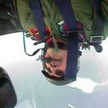
billn53 Posted July 24, 2019 Author Share Posted July 24, 2019 Here's a short progress report just so everyone knows I haven't given up on this kit, yet. The cockpit and interior are, except for a few small items, finished. I did very little to detail these, other than painting the parts as supplied, as not much will be visible when installed in the center wing section. The detailing I did do is focused on the pilot and co-pilot positions. I have yet to add the pilot & co-pilot seats because I'm waiting for some photoetch belts & harnesses. I also still need to install the control column & yokes and the gunners' periscopes. Here are some interior photos from the actual YB-35 / YB-49 aircraft for comparison: The kit instructions call out aluminum for the entire interior, as Northrop's prototypes were unfinished. Because this is going to be an operational aircraft, I referred to photos of a contemporary bomber (Convair B-36) and emulated the colors I found there. To give you an idea of how little of the kit interior will be visible once assembled, here are some photos I took while test-fitting. The parts of the interior near the pilot and co-pilot positions should be clearly visible, so the detailing I did there should pay off: This is the best I could do for trying to peer deeper into the interior. I had to use strong lighting and some image post-processing to pull out what you see here: You can also see in the above pic that the angle braces I added aren't tall enough to reach the overhead wing section. Oops! However, there should also be a set of angle braces on the other side of the interior, and these will be more easily visible as they attach near the cross-frame under the pilot's bubble canopy. Here's a construction pic I found, looking forward toward the pilot's position, showing that angle brace. You can see the opening for the canopy at the top of the photo: The area forward of the co-pilot's position also needs attention. Here's what it looks like from outside the co-pilot's glazing: There should be a bomb sight just outboard of the co-pilot's rudder pedals. Also, the empty void in the nose will likely be visible through the glazing if I don't do something about it. This is what could be seen on the actual aircraft: I can make out a curved frame with lightening holes just inboard of the glazing, which, if duplicated, should go a long way toward hiding the nose void. There is also a fair amount of cables and/or plumbing present. I'll see what I can do, there. Till next time! 20 Link to comment Share on other sites More sharing options...
mdauben Posted July 24, 2019 Share Posted July 24, 2019 An absolutely fascinating subject. I was actually looking at this model, but even in 1/72 I just don't have room to display it properly. I'll have to live vicariously though your build, instead! 😉 1 Link to comment Share on other sites More sharing options...
Corsairfoxfouruncle Posted July 24, 2019 Share Posted July 24, 2019 39 minutes ago, mdauben said: An absolutely fascinating subject. I was actually looking at this model, but even in 1/72 I just don't have room to display it properly. I'll have to live vicariously though your build, instead! 😉 110% Ditto ... Id love to build either of the Original Northrop flying wings but just cant justify the size right now. In fact I'm so limited I'm restricted to small twins like 110's and P-38's nothing more. 1 Link to comment Share on other sites More sharing options...
f111guru Posted July 24, 2019 Share Posted July 24, 2019 Turning out to be a great build. Thanks for the information photos. I know I don't have them. I do have in my stash 1 each XB-35 and XB-49, 2 XB-70's. One is the anniversary edition. Plus have 4 B-36. 2 are in the original boxes. Keep up the great work Bill Ron VanDerwarker Link to comment Share on other sites More sharing options...
billn53 Posted July 24, 2019 Author Share Posted July 24, 2019 6 hours ago, mdauben said: ... even in 1/72 I just don't have room to display it properly. I’ll cross that bridge when I get to it. 1 Link to comment Share on other sites More sharing options...
billn53 Posted July 24, 2019 Author Share Posted July 24, 2019 4 hours ago, f111guru said: I do have in my stash 1 each XB-35 and XB-49, 2 XB-70's. One is the anniversary edition. Plus have 4 B-36. That’s quite a collection of big airplanes, you must be even crazier than me, in my stash are another YB-35, a B-36, XB-70, and a 1/48 B-58. Not to mention some “smaller” aircraft in 1/32 and 1/24. Link to comment Share on other sites More sharing options...
billn53 Posted July 25, 2019 Author Share Posted July 25, 2019 My PE seatbelts came in today so I was able to pretty much finish off the cockpit and interior. I then glued the interior to the center wing section and taped the top wing in place to ensure the interior would remain properly positioned while the glue set. Here are a few pics for your entertainment: Pilot's seat: Control yoke & wheel. I re-shaped the kit's wheel to look more like Northrop's version. Added detailing behind the co-pilot's glazing. I installed backs and wiring for the instruments, stole a bombsight from the B-17 kit in my stash (if/when I get around to building that kit, I'll need to find a replacement), and added a suitably-impressive piece of equipment to help fill the nose void (actually, it's a spare carburetor from a 1/24 model car) Rear gunner's position & armor shield. Tip to anyone building this kit: disregard the instructions when it tells you to install the gunsight periscopes and the rear-gunner's armor shield. Wait to add those at the end of the build. Otherwise, they'll have a high probability of breaking long before your build is done. How do I know this... ? With the interior in place, I wanted to see how much would be visible through the kit's canopy. I noticed a couple of things right off. First, the clear parts have imperfections and will probably need to be lightly sanded and polished. More annoying is that the sprue gates are large and, after separating the canopy from it's sprue, there is a nasty scar that extends beyond the canopy frame into the clear portion. Finally, the canopy's plastic is thick, causing some serious distortion at certain viewing angles. So much for the effort I put in painting the instrument panel (grrr….. ) Oh! I almost forgot this: I cut open the under-belly's crew access hatch and will be building a new door so that I can have the hatch open. I won't be doing anything fancy like building an interior, just a simple open hatch. Tomorrow I'll untape the center wing section and start adding reinforcement bracing. 13 Link to comment Share on other sites More sharing options...
Pete in Lincs Posted July 25, 2019 Share Posted July 25, 2019 The shape of things to come..... Fascinating build. Link to comment Share on other sites More sharing options...
LorenSharp Posted July 25, 2019 Share Posted July 25, 2019 Great job with the seat harnesses 72nd scale and panel wiring. Dont know how you did it. I can barely see and work with mine at 48th scale.Excellent! Link to comment Share on other sites More sharing options...
billn53 Posted July 25, 2019 Author Share Posted July 25, 2019 10 minutes ago, LorenSharp said: Great job with the seat harnesses 72nd scale and panel wiring. Dont know how you did it. I can barely see and work with mine at 48th scale.Excellent! The harnesses are from Eduard and are pre-painted steel photoetch ( much easier to work with than brass). For close up detail work I have a pair of +6.00 reading glasses and a high Lumen head-mounted LED light. Also a pair of good-quality needle-pointed forceps. Makes a huge difference! Link to comment Share on other sites More sharing options...
mdauben Posted July 25, 2019 Share Posted July 25, 2019 12 hours ago, billn53 said: With the interior in place, I wanted to see how much would be visible through the kit's canopy. I noticed a couple of things right off. First, the clear parts have imperfections and will probably need to be lightly sanded and polished. More annoying is that the sprue gates are large and, after separating the canopy from it's sprue, there is a nasty scar that extends beyond the canopy frame into the clear portion. Finally, the canopy's plastic is thick, causing some serious distortion at certain viewing angles. So much for the effort I put in painting the instrument panel (grrr….. ) Back a number of years ago, the last time I was actively involved in building model planes, it seemed like doing vacuformed replacement canopies was almost a requirement for "serious" modelers. For the last couple weeks I've been reading things here on Britmodeller, though, I have not seen anyone mention doing vacuformed canopies in their build or finished threads. Might that be something worth doing to make your cockpit detailing more visible? Or is it not practical for the clear parts on this model? 1 Link to comment Share on other sites More sharing options...
billn53 Posted July 26, 2019 Author Share Posted July 26, 2019 11 hours ago, mdauben said: Back a number of years ago, the last time I was actively involved in building model planes, it seemed like doing vacuformed replacement canopies was almost a requirement for "serious" modelers. For the last couple weeks I've been reading things here on Britmodeller, though, I have not seen anyone mention doing vacuformed canopies in their build or finished threads. Might that be something worth doing to make your cockpit detailing more visible? Or is it not practical for the clear parts on this model? You’ve been reading my mind, haven’t you? I built many model planes back in the ‘70s and ‘80s, and just like you said, vacuforming was much more common than it is today. I suspect that is because the quality of clear parts is so much better than it once was. Anyway, I do have access to a vacuform machine and have used it a few times since I got back into the hobby. My results have been mixed. It might be the answer for my YB-35 build... but the canopy might be a problem because it is so high and the sides are nearly vertical. Only one way to find out, of course! 1 Link to comment Share on other sites More sharing options...
RidgeRunner Posted July 26, 2019 Share Posted July 26, 2019 Nice work, as always, Bill Link to comment Share on other sites More sharing options...
Retired Bob Posted July 26, 2019 Share Posted July 26, 2019 Hi Bill, I have dug out my main reference for the Northrop Flying Wings, a Schiffer publication but there is not much different than you have posted. Are you going for the projected version that had the counter-rotating propellers or the single screws like on the box art? The USAF had a preliminary order for 200 B-35s if Jack Northrop could make it work. Link to comment Share on other sites More sharing options...
billn53 Posted July 26, 2019 Author Share Posted July 26, 2019 9 minutes ago, Retired Bob said: Are you going for the projected version that had the counter-rotating propellers or the single screws like on the box art? The USAF had a preliminary order for 200 B-35s if Jack Northrop could make it work. I can't resist the counter-rotating props! In talking about my build with others in my local modeling group, I've found few are aware of just how many wings Jack Northrop built before the Government cancelled his contract. Here are a couple of eye-opening photos: As far as my build goes, I'm very close to being ready to assemble all the major pieces, so here's a last look at the completed interior before it disappears! 16 Link to comment Share on other sites More sharing options...
Brandy Posted July 26, 2019 Share Posted July 26, 2019 (edited) If you're thinking of vac forming a canopy, both @perdu and @Fritag have some excellent tips on their latest builds. You could do worse than to check them out. Ian Sorry, I'm on my phone at the mo and can't figure out how to add links! Edited July 26, 2019 by limeypilot 1 Link to comment Share on other sites More sharing options...
f111guru Posted July 26, 2019 Share Posted July 26, 2019 (edited) Coming along quite nicely Billn53. Interior is looking sharp. I have a smaller version of the Northrop flight line. I have some pdf files of the Northrop erection manuals, parts and flight. Don't remember where I got them from. Maybe this site: https://ww2aircraft.net/forum/ But not 100% sure. Has some excellent information. Plan on using those to build one of mine in my stash. Great work so far. Keep it up Ron VanDerwarker Edited July 27, 2019 by f111guru 1 Link to comment Share on other sites More sharing options...
billn53 Posted July 27, 2019 Author Share Posted July 27, 2019 Just four weeks before our local show & contest. I feel like I'm making steady progress and there's a good chance I'll be done on time. Here's today's achievements: The last mod to the wing center section was to add the warm air exhaust openings & flaps at the rear, between the engines. They are clearly visible in this in-flight photo: First step was to open the vents on the upper wing surface: I used a scraper to thin the rear edge of the opening, working on the underside of the upper wing piece, and then glued some thin plasticard to create a "floor" to the vent opening: The vent doors / flaps will not be added until after I'm done with filling & sanding -- just before painting. While I was at it, I did a minor repair to the wing trailing edge, right near the flap opening. The corners on both sides (right and left) had broken off while in the box. For this fix, I simply added a thin piece of plasticard, which I'll shape and putty after the top & bottom pieces are glued together. That done, I proceeded to add various stiffening members, as recommended by Jeff. I followed the pics in his build log, so I won't go into the details. Here's what I ended up with: My last achievement today was to add the nose weight. The instructions call for 120-grams (4 ounces), and I was worried that I might not find room for that much lead. Happily, I succeeded: I used self-adhesive 7-gram lead weights. I don't trust the adhesive at all, and last thing I would want is a quarter-pound of lead rattling around in my model. I intend to box in the weights and fix them in place with epoxy putty. But the adhesive was good enough for me to do a balance test. I installed a surrogate for the main landing gear using thick styrene sheet: I then taped everything together and, holding my breath, lowered my wing onto its styrene stilts. Success! No tail-sitter here! Having everything taped together reminded me how big this airplane is. There is hardly room for it on my work table. I plan to treat this as three separate models as long as possible: two wings, and a center section. I'll assemble each, fill gaps, sand, prime, etc. and, once I'm happy, only then merge the three sections together. That's it for today. I have the entire weekend ahead of me. Let's see how far along I can be by Monday. 18 Link to comment Share on other sites More sharing options...
f111guru Posted July 27, 2019 Share Posted July 27, 2019 WOW love the super structure. That should keep it square. Great work, progressing very nicely. Storing your ideas in my cobwebbed long term memory. Found these in my archive for building thought. May attempt the spit rudder on one of my future builds. Ron VanDerwarker 4 Link to comment Share on other sites More sharing options...
Retired Bob Posted July 28, 2019 Share Posted July 28, 2019 Hi Bill great progress, I would use the sprue gloop in several layers to restore your missing corners, I have no faith in ANY filler not cracking or breaking off on an edge like that, and I would also varnish the wood to prevent any chance of warpage over the years, but perhaps I overthink things and that's why my build rate is so low. 1 1 Link to comment Share on other sites More sharing options...
billn53 Posted July 28, 2019 Author Share Posted July 28, 2019 31 minutes ago, Retired Bob said: Hi Bill great progress, I would use the sprue gloop in several layers to restore your missing corners, I have no faith in ANY filler not cracking or breaking off on an edge like that, and I would also varnish the wood to prevent any chance of warpage over the years, but perhaps I overthink things and that's why my build rate is so low. Thanks Bob! Good idea on the sprue gloop, don’t know why I didn’t think of that straight off. Too late for me to do anything to the reinforcing wood, however. 1 Link to comment Share on other sites More sharing options...
Serkan Sen Posted July 28, 2019 Share Posted July 28, 2019 (edited) On 7/25/2019 at 1:00 AM, billn53 said: That’s quite a collection of big airplanes, you must be even crazier than me, in my stash are another YB-35, a B-36, XB-70, and a 1/48 B-58. Not to mention some “smaller” aircraft in 1/32 and 1/24. I had also similar collection besides the russian bombers&cargo planes and british V bombers in 72 scale. But due to limited display cases at home I had to let most of them go... 😞 What I still have is vacuform XB-70 waiting on the bench to finish... Serkan Edited July 28, 2019 by Serkan Sen Link to comment Share on other sites More sharing options...
billn53 Posted July 28, 2019 Author Share Posted July 28, 2019 Sunday afternoon update! First up, I added a minor addition to my warm air vent openings on the wing trailing edges. I realized that, because the plasticard I'll be using for the vent doors is so thin, I needed to add styrene strip to create a step for the doors at the forward edge of the vent opening: My next task was to tackle the turrets at top and bottom of the center wing section. Since I'm building a B-35 production aircraft, it will be fully-armed with defensive 50-cal guns. This is the pic I've been able to find that details the turret arrangement: The kit represents prototype aircraft, in which the turrets were only unarmed mock-ups. Here's what the four-gun turrets look like in the kit: My challenge was to make these look like production items, which meant opening up the slots for the guns. Using a sharp scriber, I first deepened the outlines for the four gun slots. Then, I used the back of a 1-mm chisel as a scraper to create trenches for a 3D appearance: Add a little black paint, and the illusion is complete: I'll add the gun barrels after painting is done. Another small item -- I found this photo showing the top of the cockpit opening: So I added a bit of cabling on the brace behind the pilot's seat: With all of the mod work done on the center section, it was nearly time to button everything up. I epoxied the lead weights in place and boxed them in with wood for good measure: Test fitting revealed that there was a problem with the clear glazing for the copilot and bombardier. The centerline frame stuck out too far from the aircraft's nose, and the lower glazing had significant gaps: After a lot of fettling things began to look better, but I chickened-out and quit when a hairline stress crack developed in the bombardier's window: Finally, everything was ready for me to glue the top and bottom together. I began with the nose: Next, I glued the tail section. Test fitting showed I needed a shim to prevent a step when I add the tail cone: Further test fitting with the leading edge / air intake pieces convinced me to leave that part of the wing "floating" for now: Instead, I glued the center section ends together, trimming as necessary to minimize any step when the outer wing sections are added: And, taking Retired Bob's advice, I applied a layer of sprue gloop to the trailing edge corner repairs I noted earlier: That's where everything stands at present. The center and outer wing sections have been assembled. I'll do as much cleanup on those as I can before joining them together. I'm a long way from done, but considering I started this build just over a week ago, things are moving ahead quickly! 13 Link to comment Share on other sites More sharing options...

Recommended Posts
Create an account or sign in to comment
You need to be a member in order to leave a comment
Create an account
Sign up for a new account in our community. It's easy!
Register a new accountSign in
Already have an account? Sign in here.
Sign In Now