opus999 Posted April 17, 2019 Share Posted April 17, 2019 On 4/14/2019 at 8:37 PM, billn53 said: It's Sunday night and the weekend is nearly over. I had hoped to get the DSO's office done today, but I fell into the trap of "more detail is better" and spent most of the day working on the Pilot and Navigator stations. I added the throttle levers and some miscellaneous handles in the cockpit: But in the Navigator/Bombardier station I went totally out of control on the forward panel. Basically, I thought the Airwaves PE panel looked too "2-D", so I proceeded to drill about three dozen holes, using photos of the real panel for guidance, and inserting minuscule pieces of styrene rod for the knobs & switches. Below is an "in process" pic, and another after painting everything up: At long last, I finally began work on the DSO's station. Below is a comparison of Italeri's panel with the Airwaves version: And my progress today at roughing out the DSO's consoles and side panels: That's it for this update. Hopefully by the next one, I'll have all three stations done and have started work on the escape capsules. Wow. That looks fantastic! 3 1 Link to comment Share on other sites More sharing options...
billn53 Posted April 18, 2019 Author Share Posted April 18, 2019 Help! Somebody please stop me before I add details again! I'm sorry to say that I haven't yet begun working on the Hustler's unique escape capsules. Instead, I'm still stuck on the three crew stations. I began today by cleaning up the rear bulkheads. Italeri molded in some features that I've yet to see in any photos. So, out with my chisel and Presto! They were history. Next, I temporarily fixed the crew stations in the fuselage in order to properly align the side panels. Once positioned, I glued the panels in place: This is when I went off track! Just because I could, I decided to scratch build the Navigator and DSO's desks, which are stowed beneath the forward panel. Here's the real thing, and my version: Then I decided to add the crew's escape ropes: And, remember the pilot's cubby hole? I filled it with its normal contents: a nuclear flash "sun shade": All that done, I did a test fit of the crew positions to ensure I will have no problems gluing the fuselage together. It's a tight fit, and I'll need to use some claps, but that test was successful. However, I did discover a minor problem: the Navigator's forward panel is sitting too low, creating a visible gap above the panel: It's too late to raise the panel, so my solution was to build an arch to hide the gap: Once the arch is puttied up, and painted panel-gray, I'm hoping the gap will be nearly invisible. That's all for this update. More to come. 8 Link to comment Share on other sites More sharing options...
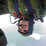
Andwil Posted April 18, 2019 Share Posted April 18, 2019 Fabulous detailing, I love the escape ropes. How did they work in reality? The sticker alongside says 1. Grasp rope firmly 2. Jump over side... the rest is too small to read. Obviously for rapid exit on the ground, sort of an abseil arrangement. AW 1 Link to comment Share on other sites More sharing options...
billn53 Posted April 18, 2019 Author Share Posted April 18, 2019 4 hours ago, Andwil said: Fabulous detailing, I love the escape ropes. How did they work in reality? The sticker alongside says 1. Grasp rope firmly 2. Jump over side... the rest is too small to read. Obviously for rapid exit on the ground, sort of an abseil arrangement. AW Here's the full text: 1. Grasp handle firmly 2. Jump over side Brake will check speed of descent According to the Flight Manual, each escape rope is approximately 29 feet long. Besides the two I've modeled so far, the pilot also has an escape rope. His is located behind on the left side, behind the canopy framing. I'll see about getting to that one when I'm doing the canopy. 2 1 Link to comment Share on other sites More sharing options...
Andre B Posted April 18, 2019 Share Posted April 18, 2019 (edited) 19 hours ago, billn53 said: Here's the full text: 1. Grasp handle firmly 2. Jump over side Brake will check speed of descent According to the Flight Manual, each escape rope is approximately 29 feet long. Besides the two I've modeled so far, the pilot also has an escape rope. His is located behind on the left side, behind the canopy framing. I'll see about getting to that one when I'm doing the canopy. And if the brake doesn't... ? Edited April 19, 2019 by Andre B Link to comment Share on other sites More sharing options...
billn53 Posted April 18, 2019 Author Share Posted April 18, 2019 1 hour ago, Andre B said: And of the brake doesn't... ? That's what we call a "quick trip" 1 Link to comment Share on other sites More sharing options...
Witman61 Posted April 20, 2019 Share Posted April 20, 2019 (edited) Her is my five cents in this thread: static dischargers – in my project I have used Master Model offering made for F-16 (No AM-72-092). The pictures and drawings I have followed are shown below - the source was relevant www sites. It is great news Eduard is going to issue a some aftermarket sets for the Italeri kit. There will be interior and exterior PE sets plus masks. Seems rich comparing to the limited Airwaves offering. Think about the instrument panels in colours! They have just recently issued resin nuke bombs in 1/72 scale (No 672214 & 672215) – in my opinion - much more realistic than the ones included in the kit. Edited April 20, 2019 by Witman61 text corrections 1 1 Link to comment Share on other sites More sharing options...
billn53 Posted April 20, 2019 Author Share Posted April 20, 2019 3 hours ago, Witman61 said: Her is my five cents in this thread: static dischargers – in my project I have used Master Model offering made for F-16 (No AM-72-092). The pictures and drawings I have followed are shown below - the source was relevant www sites. It is great news Eduard is going to issue a some aftermarket sets for the Italeri kit. There will be interior and exterior PE sets plus masks. Seems rich comparing to the limited Airwaves offering. Think about the instrument panels in colours! They have just recently issued resin nuke bombs in 1/72 scale (No 672214 & 672215) – in my opinion - much more realistic than the ones included in the kit. You've been reading my mind! I'm expecting my Master Models static discharges to arrive any day now, and I've ordered a few of the new Eduard PE sets. The interior set will probably be too late for this build, but I'm hoping the set for exterior details will help with my landing gear & bays. Thanks for the pics & drawing of the Hustler static dischargers. In most photos I've found, the dischargers can't be seen, which makes me wonder if only some aircraft had them. That would be no surprise, as I've found lots of variations from one plane to another, especially with interior details. Link to comment Share on other sites More sharing options...
Space Ranger Posted April 20, 2019 Share Posted April 20, 2019 (edited) Lengths of fine nylon brush bristles make good static dischargers; being flexible, they are less likely to break off while handling the model. But the Master Model items sound interesting. It appears from photos that the dischargers are mounted on the upper surface of the wingtips, but on alternate sides of the rudder. Edited April 20, 2019 by Space Ranger 1 1 Link to comment Share on other sites More sharing options...
billn53 Posted April 21, 2019 Author Share Posted April 21, 2019 10 hours ago, Space Ranger said: Lengths of fine nylon brush bristles make good static dischargers; being flexible, they are less likely to break off while handling the model. But the Master Model items sound interesting. I do have a huge supply of nylon bristles, in various sizes, and enough to last many, many lifetimes. That was my fall-back in case I couldn't find any AM, but Eduard's F-16 static dischargers looked like they will fit the bill so that's what I ordered. I'm encouraged to learn that those are exactly what Witman61 used on his gorgeous build. 1 Link to comment Share on other sites More sharing options...
billn53 Posted April 21, 2019 Author Share Posted April 21, 2019 Wow! It's been a few days since I posted my last update, so let me bring everyone up to speed. But before I go there, an absolutely gorgeous Hustler RFI was recently posted by Witman61, which just has to be seen! Check it out here: When I see modeling like that, especially on a kit I'm in process of building myself, I'm tempted to throw in the towel and quit right now. But there's also a part of me that is inspired to do as well. As far as Witman61's build goes, if I can come close to that level of skill, I'll count myself lucky! Anyway, back to my latest work. When last I posted, I had just about finished working on the B-58's three crew stations. Since then, I've focused my attention on the crew escape capsules. One of the rewards I enjoy in this hobby is learning about the subjects I'm modeling. The Hustler's escape capsule design is an excellent example. Early production aircraft were equipped with traditional ejection seats, which proved deficient for supersonic ejections. To provide greater protection for the crew, Convair tasked Stanley Aviation to develop a fully-encapsulating escape pod for the B-58. I don't envy the designers who were assigned this task -- the capsule would have to fit in an aircraft that had already been built, so design options were severely constrained. Here's what they came up with: The capsule served two purposes. First, if cabin pressure should be lost, the capsule could be manually closed, which would maintain a safe environment for the crew. (The pilot's capsule included the joystick, allowing limited but sufficient control of the aircraft for a safe landing.) Of course, the second purpose of the capsule was to protect the crew during a high-speed ejection. On ejection, stabilization booms with fins on the end would extend and a drogue parachute would deploy to stabilize the capsule prior to main chute inflation. In case of a water landing, four telescoping booms with flotation bags would keep the capsule buoyant. Here is a detailed diagram for reference: The first thing I did was to compare the kit's capsules with drawings of the actual item: Italeri captured the basic shape, but details are missing. I also noticed that the back of the upper capsule needed to be trimmed slightly (red line in the photo above). This will be important to provide room for some of the back-side details, and for more realistic ejection rails (more on this, later). The kit parts also have some nasty mold lines that must be sanded down. Thus far, I've focused on adding exterior detail to the upper-half of the ejection capsule -- not much else will be visible once the capsules are installed in the fuselage, as is apparent in the following pic: Let's see how well I've done! Items I've added are: the twin strakes that run front-to-rear on the top of the capsule, the external latch assemblies for opening the capsule (just forward of the strakes); caps for the upper flotation booms; and on the rear of the capsule, the two stabilization booms; shock absorbers; mortar; and drag plate. Next on my list of things to do are the capsule bottom section, and interior detailing. For the latter, here's Italeri's version compared to the real item: Plenty of opportunities there to go overboard with detailing that might never be seen LOL! In addition to working on the escape capsules, I also gave some attention to the ejection rails on the rear bulkheads of the crew compartments. The kit's moldings don't look anything like actual ejection rails: So, once again I broke out my trusty chisel and made the kit's version history: I used strips of right-angle styrene to better replicate the Hustler's ejection rails. These I attached to a small rectangle cut from styrene sheet, to properly space the rails and ensure they are parallel: And this is how things look with the capsule test-fitted in place: Not too bad! Before I sign off, a couple of interesting factoids I discovered in my research: 1) The pilot's seat was positioned slightly left of the aircraft centerline (to move the pilot's line of sight away from the canopy center post), and his ejection rails were canted at an angle to compensate. Check out the below photo of an abandoned Hustler in the Mojave Desert: Remember earlier when I noticed the pilot's instrument combing is asymmetric? Looks like that's not the only thing off-center there. Oh well, too late to do anything about it now... 2) This was perhaps the only time that a bear has been ejected from a supersonic aircraft. No kidding! During development testing of the Stanley capsule, the Air Force didn't want to risk human subjects, so bears (whose internal organ layout is similar to a person's) were tranquilized, strapped in, and ejected (safely) from a B-58 in-flight! See video here: https://www.dailymail.co.uk/video/news/video-1250/NOTE-Some-distressing-Drugged-BEARS-used-test-ejector-seats.html Reportedly, one of the bears ended up stuffed for display at the Edwards AFB test flight museum. Truth is indeed stranger than fiction! That's it for now. Till my next post, happy modeling! 4 Link to comment Share on other sites More sharing options...
Space Ranger Posted April 22, 2019 Share Posted April 22, 2019 56 minutes ago, billn53 said: In addition to working on the escape capsules, I also gave some attention to the ejection rails on the rear bulkheads of the crew compartments. The kit's moldings don't look anything like actual ejection rails: 1) The pilot's seat was positioned slightly left of the aircraft centerline, and his ejection rails were canted at an angle to compensate. Check out the below photo of an abandoned Hustler in the Mojave Desert: That appears to be a standard ejection seat, as used on some of the early B-58s, but I believe the seat rails were the same. Stanley Aviation, the developer of the supersonic seat capsule, was founded by Robert Stanley. As a civilian test pilot for Bell Aircraft, he became the first American to fly a jet aircraft on October 2, 1942, when he flew the Bell XP-59A Airacomet at Muroc Dry Lake, California. He was born in El Reno, Oklahoma, and in 2001 he was inducted into the Oklahoma Air and Space Hall of Fame as a result of my nomination. I also accepted the award on behalf of his daughter and grandsons, who could not attend the induction ceremony, coming so soon as it did after the terrorist attacks on the World Trade Center and Pentagon. The derelict B-58 in the photo is what's left of "Snoopy," s/n 55-0665, built as a YB-58A and later redesignated B-58A. It was specially modified to test the Hughes radar system for the for the GAR-9/AIM-47 missile intended for the Lockheed YF-12 interceptor and the North American F-108 Rapier, and had an extended nose to accommodate the radar. This aircraft sits derelict as a photo target on Edwards AFB's photo range and can be seen in Google Earth at 34.816163°N, 117.863709°W. In summer 1994 I was a master's degree graduate student and historic preservation intern at Edwards, and crawled all over and around that aircraft surveying it and documenting it in photographs for the possibility of its restoration. My examination was cut short by a mother hawk who had nested inside the fuselage and was not very happy about my presence, but I saw enough to conclude that restoration would be hopeless without having to cannibalize all the other surviving B-58s on display. There was just not enough left of it, and 25 years years later, I can't imagine that its condition has changed for the better. 2 2 Link to comment Share on other sites More sharing options...
billn53 Posted April 22, 2019 Author Share Posted April 22, 2019 Michael -- Thanks so very much for your firsthand info. There's a huge difference between reading about things, and hearing about it from those who were there. 1 Link to comment Share on other sites More sharing options...
Getting Old Posted April 22, 2019 Share Posted April 22, 2019 Fantastic work, so impressive 1 Link to comment Share on other sites More sharing options...
hairystick Posted April 22, 2019 Share Posted April 22, 2019 Great work so far on those cockpits. I've got the same kit "started" (insert hysterical laughter here) predominatly on the nacelles as I intended to foil the kit. With one pod covered, I now want to de-foil it and use alclad metallic paints instead. Sadly I've yet to develop an un-glue system! The small cable (clothes-line) seems to run between the cockpits. What is it for??? Surely not passing paper notes between the crew? Link to comment Share on other sites More sharing options...
billn53 Posted April 22, 2019 Author Share Posted April 22, 2019 3 hours ago, hairystick said: The small cable (clothes-line) seems to run between the cockpits. What is it for??? Surely not passing paper notes between the crew? Yes, that is exactly what it is for. 1 Link to comment Share on other sites More sharing options...
billn53 Posted April 22, 2019 Author Share Posted April 22, 2019 Passing along this video I found, on B-58 escape capsule testing: - Bill 1 Link to comment Share on other sites More sharing options...
billn53 Posted April 24, 2019 Author Share Posted April 24, 2019 Just a few pics to show I haven't been idle. I'm calling the escape capsules' upper section done. All that's left there is to add the shoulder harnesses and oxygen hoses. I'll do that after I join the top and bottom sections together. Viewed from above, you can see the added strakes, latch assemblies, yellow flotation boom cover; black shock absorbers; drogue parachute mortar; and drag plate: In this frontal view, you can see I added two triangular equipment bays either side of the headrest. The oxygen hose will attach to the one over the crew member's right shoulder. You can also see the "green apple", which is the manual actuator for the capsule's oxygen and pressurization system. Just above the back cushion are containers for survival gear: Compare with what I had to start with: And yes, you need not remind me that I earlier said, "Plenty of opportunities to go overboard with detailing that might never be seen..." Next up, the capsule's bottom section. 5 Link to comment Share on other sites More sharing options...
Nikolay Polyakov Posted April 24, 2019 Share Posted April 24, 2019 Outstanding work with a capsules, @billn53! 👍 And many thanks to @Space Ranger for a very informative article. I must say that the builds like this become a great reference articles and can be as useful (or even more), as some prominent books. Cheers! 🙃 1 Link to comment Share on other sites More sharing options...
billn53 Posted April 27, 2019 Author Share Posted April 27, 2019 Escape capsules are finished and I'm on the verge of closing the fuselage. When I last left off, I had completed work on the capsules' upper section and was about to start on the lower half. First, I built the ejection arms & handles using styrene strip. The styrene strip became weak where it was bent for the arms, and I broke a couple. I should have used brass rod instead. But I learned my lesson and used brass for the lower frame piece: Then I added the leg retraction arms, also from brass and painted painted everything up: Here is how the seats turned out after joining the upper & lower sections. A reasonable facsimile of the actual seat, I propose: I added seatbelts (from the AirWaves PE set) and oxygen hoses (that I scratched by winding thin wire around a larger wire), then installed the assembled seats into the three crew compartments: This is a closeup of the pilot's station with seat installed: and the stations for the Navigator/Bombardier and Defensive Systems Officer: I next did another test to confirm there will be no nasty surprises when I close up the fuselage: Here are a few shots to give you a feel for how much (or little) of my work will be visible with the fuselage assembled: Pilot Station: Not too bad, but remember, there is still a canopy/windscreen to install: Navigator/Bombardier Station: DSO's office: So, there you have it. Crew stations are done and I'm just about ready to start building an airplane. Before gluing the fuselage halves together, though, I thought it wise to take care of a couple little items. The Hustler's tail has two red position lights - one on the upper leading edge of the vertical stabilizer, the other on the rear just above the tail cone. I intend to install red acrylic to simulate these lights (this will be a first for me, and I'll have my fingers crossed when I get to that part -- anyone with tips on this, send them my way), which requires cutting out parts of the kit plastic. Best to do this before the fuselage interior, wings, etc. are in place: That's all I have for now. For the next post, I plan to have the fuselage assembled and work started on the engine pods. 9 Link to comment Share on other sites More sharing options...
billn53 Posted April 28, 2019 Author Share Posted April 28, 2019 Got the interiors installed and closed the fuselage at last! I had to glue the fuselage halves literally an inch at a time, starting with the upper join at the nose, moving down the back of the fuselage using multiple clamps, rubber bands, and tape, and then repeating the process along the belly: I also added one of the two red lights I mentioned earlier. It was much easier than I had feared (never having done this before), and looks like the cat's meow! I'll wait until tomorrow to do the other light. First, I want to be sure the glue holding the fuselage together has fully set. Also, this light is in a tough place to work on, and I'll need a good night's rest before taking on that task. 6 Link to comment Share on other sites More sharing options...
Retired Bob Posted April 28, 2019 Share Posted April 28, 2019 Just caught up with this thread, very impressive work and some great info (whole new meaning to the phrase "there's a bear in the air") For my sins I bought four of these when they first came out, mainly because there were four choices on the Microscale sheet and I thought "what the heck" I like delta winged aircraft. Perhaps I will dig one out of the stash soon? Link to comment Share on other sites More sharing options...
billn53 Posted April 28, 2019 Author Share Posted April 28, 2019 1 hour ago, Retired Bob said: Just caught up with this thread, very impressive work and some great info (whole new meaning to the phrase "there's a bear in the air") For my sins I bought four of these when they first came out, mainly because there were four choices on the Microscale sheet and I thought "what the heck" I like delta winged aircraft. Perhaps I will dig one out of the stash soon? 1 hour ago, Retired Bob said: For my sins I bought four of these when they first came out.... I know what you mean! In my stash I have another Italeri B-58, the 1/48 Revell-Monogram kit, one in 1/144, and (for nostalgia's sake) the ancient (nearly as old as me) Lindburg 1/192 Hustler. 1 Link to comment Share on other sites More sharing options...
billn53 Posted April 28, 2019 Author Share Posted April 28, 2019 Now that the interior detailing is done, and I've started assembly of the actual airframe, my will be on achieving as perfect a surface as possible for the metallic finish that will come later. On inspecting the fuselage after having glued the halves together, I began to realize the size of the task ahead of me. Not only do I have imperfect joins to contend with: but the kit's plastic must be cleaned up as well: To hone my skills, I will use the seam along the fuselage bottom as my test subject. Most of this seam will be covered by the Hustler's big underbelly pod, so any screwups on my part should hopefully be hidden. My first step was to scrape down the areas that had a step at the seam. I have a new tool in my toolbox and this was a prime opportunity to give it a spin: The price was exorbitant, but the quality of this scraper blade is a joy to behold: At first, I was a bit too heavy handed, and succeeded both in removing the step and in creating a trench along the seam :-(( But I'm starting to get the feel for this tool, and my later efforts were less destructive: After the scraping, I added tape to protect the surrounding surface, and wet sanded the seam with a medium-grit sanding stick: I then cleaned up the resulting mess, applied some new tape, and went over the seam with Mr Surfacer 500. When that's dry, I'll sand the seam, inspect for defects, and repeat as necessary until the finish looks good. Undoubtedly, I'll need to re-scribe some panel lines before putting on the primer coat. I foresee this will be a long, tedious process. And, I'm dreading what will be involved when I get to the engine pods, pylons, and centerline weapon pod. Ugghhh! On a more positive note, I successfully added the second red light on the Hustler's tail, and I'm satisfied with the result. I'll need to do this a couple more times when for the wing position lights. 3 Link to comment Share on other sites More sharing options...
Retired Bob Posted April 29, 2019 Share Posted April 29, 2019 22 hours ago, billn53 said: The price was exorbitant, but the quality of this scraper blade is a joy to behold: WOW! that looks one mean tool, are you sure it's not for skinning whales. I always wanted a B-58 with the two component pod, looked impressive but so does a fuel tank and 4 x Mk 43's. I was always tempted by the Monogram B-58, but somehow I managed to resist, must have been the surface area of NM finish. Link to comment Share on other sites More sharing options...

Recommended Posts
Create an account or sign in to comment
You need to be a member in order to leave a comment
Create an account
Sign up for a new account in our community. It's easy!
Register a new accountSign in
Already have an account? Sign in here.
Sign In Now